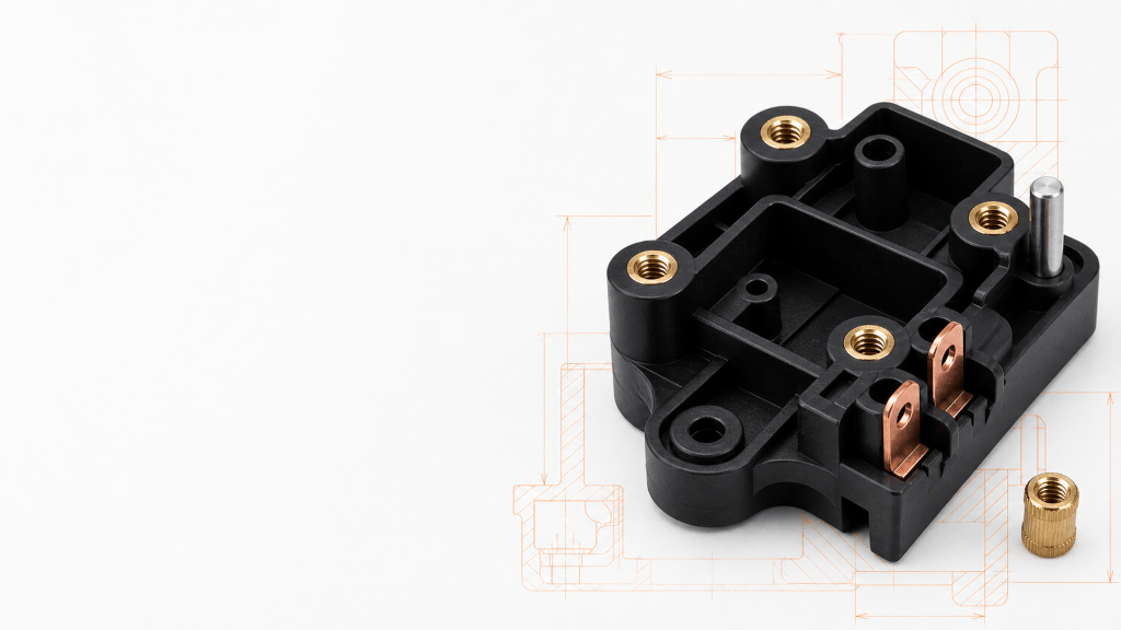
Insert injection molding combines a premanufactured component with molten plastic in a single molding cycle. The insert may provide a reusable thread, an electrical path, a wear surface, a locating feature or a structural reinforcement that plastic alone cannot provide.
The process can produce a strong, compact assembly with fewer secondary operations. It also introduces risks that do not exist in conventional molding. An insert can move under injection pressure, block plastic flow, create a knit line or concentrate stress as the plastic cools. A successful part therefore depends on the insert, plastic geometry, mold and loading method being developed as one system.
Quick answer: Insert injection molding is most effective when the insert has positive mechanical retention, the mold locates it repeatably, plastic can flow around it without trapping air, and the finished assembly is validated with tests that reflect its real service loads.
What Is Insert Injection Molding?
In insert injection molding, an operator or automated system places a metal, ceramic or previously manufactured component into a mold cavity. The mold closes around locating features, molten polymer fills the remaining cavity, and the plastic solidifies around the insert. The finished part leaves the mold with the insert already integrated.
Common examples include plastic housings with brass threads, electrical connectors with copper terminals, knobs molded around steel shafts, medical components containing needles or filters, and rotors containing magnets. The insert does not simply sit inside the plastic. Its external features and the surrounding plastic geometry must resist the forces that the assembly will experience.
For a broader view of resin, tooling and production options, see our custom injection molding services.
How the Insert Molding Process Works
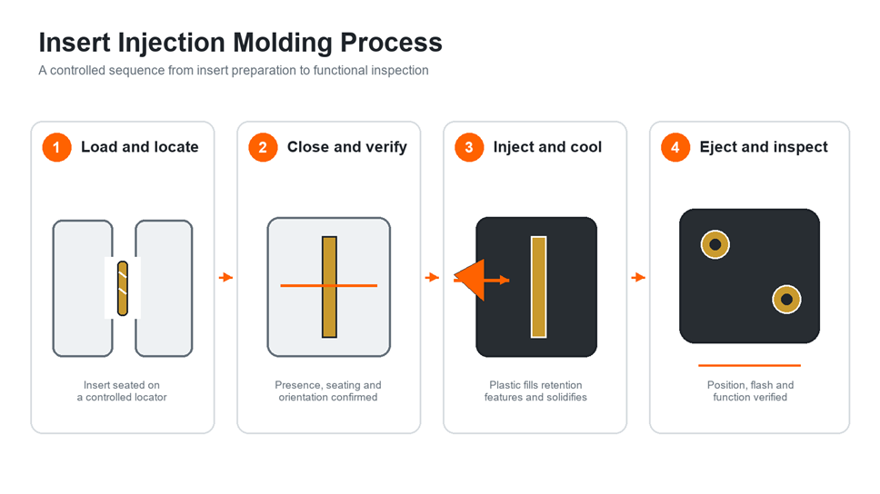
1. Prepare and inspect the inserts
The process begins before the mold closes. Inserts should be checked for dimensions, burrs, oil, plating residue, thread damage and mixed part numbers. Surface contamination can interfere with plastic flow and adhesion. Burrs can damage a locating pin or prevent the insert from seating fully.
Drying or preheating may be appropriate for some insert and resin combinations, but the correct condition depends on the material system and part requirements. The goal is repeatable molding, not simply a hotter insert.
2. Load and positively locate each insert
The insert is placed on a core pin, into a nest or between mold features that define its position. Loading may be manual, robotic or performed on a rotary-table machine. A good locating scheme controls axial position, radial position and orientation without depending on friction alone.
The mold must also prevent the insert from lifting or shifting when plastic enters the cavity. Symmetrical inserts reduce orientation mistakes. Sensors, vision checks or a mechanical poka-yoke can confirm that the correct insert is present and fully seated before mold closure.
3. Inject, pack and cool the plastic
Molten polymer flows around the insert and fills its grooves, knurls, undercuts, holes or other retention features. Gate location, flow length, venting, injection speed and packing pressure all affect encapsulation quality.
If two flow fronts meet behind the insert, they create a knit line. That line may be harmless in a lightly loaded cover, but it can become a weak location in a pressure-containing or highly stressed part. Mold-filling analysis and short-shot trials are useful when the insert significantly divides the flow.
Cooling deserves equal attention. Metal and plastic conduct heat at different rates and contract by different amounts. Excessive local packing or an abrupt plastic section around the insert can leave residual stress that later appears as cracks, warpage or loss of retention.
4. Eject and inspect the finished assembly
Ejection forces should act on stable plastic surfaces and should not pull on the insert. Initial approval normally includes dimensional checks, sectioning and mechanical testing. Production inspection may add vision, electrical continuity, torque, pull-out or leak testing according to the application.
Insert Molding, Overmolding and Post-Installed Inserts
These processes are related, but they solve different problems.
|
Method |
What is placed in the mold or part |
Typical advantage |
Main consideration |
|
Insert molding |
A discrete metal or nonplastic component |
Integrates threads, conductors or reinforcement in one molding cycle |
Insert location and resistance to injection pressure |
|
Overmolding |
A molded substrate or rigid component receives a second polymer |
Adds grip, sealing, cushioning or a second material function |
Material bonding and substrate distortion |
|
Post-installed insert |
An insert is installed after the plastic part is molded |
Simplifies the mold and avoids insert-loading time |
Adds a secondary operation and requires a correctly designed boss |
Post-installed heat, ultrasonic, press-in and self-tapping inserts can be better when cycle time, mold protection or part variety matters more than one-cycle integration. Molded-in inserts are attractive when high retention, precise integration or elimination of a secondary assembly step justifies the added tooling and loading controls. SPIROL notes that molded-in inserts receive unrestricted plastic flow around their retention features, but actual performance still has to be verified in the intended plastic assembly. See the manufacturer’s molded-in insert guidance.
For a detailed comparison with two-material molding, read our overmolding production guide.
Common Types of Molded-In Inserts
Threaded inserts
Brass, aluminum and stainless-steel threaded inserts provide reusable internal threads for screws and serviceable assemblies. Blind inserts protect the internal thread from plastic. Through-hole inserts may need a core pin or sealing feature that prevents flash from entering the thread.
Pins, shafts and bushings
Steel pins, axles and bushings can provide bearing surfaces, alignment or wear resistance. Flats, grooves, shoulders and cross holes often provide better rotational and axial retention than a smooth cylinder.
Electrical terminals and busbars
Copper alloy terminals, contacts and busbars are used in connectors, power distribution parts and sensors. Critical concerns include terminal position, sealing, flash, electrical spacing, plating protection and the effect of molding temperature on the terminal assembly.
Magnets, sensors, filters and mesh
Magnets must be oriented and retained against both injection pressure and later service forces. Sensors need protection from temperature, pressure and moisture paths. Filters and mesh require complete edge encapsulation without blocking the functional open area.
Insert Molding Design Guidelines
Create mechanical interlock
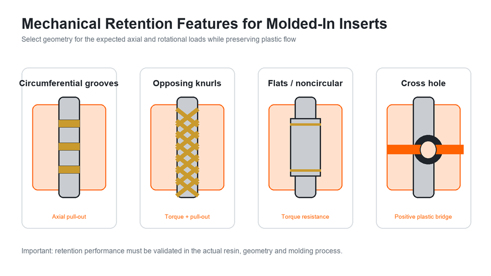
Do not expect a smooth insert surface to provide reliable retention. Use features that let plastic lock around the insert, such as opposing knurls, circumferential grooves, flats, shoulders, barbs, undercuts or cross holes. Match the retention feature to the expected load:
- Circumferential grooves and shoulders resist axial pull-out.
- Longitudinal knurls, flats and noncircular sections resist torque.
- Cross holes allow plastic to form a positive bridge through the insert.
- A head or flange can resist pull-through when the load direction is known.
Retention features must still allow resin to flow and air to escape. Very sharp knurls or thin plastic webs can create local stress instead of useful strength.
Give the mold a repeatable locating surface
The insert drawing should identify the surfaces that control seating, orientation and perpendicularity. A core pin should fit well enough to control the insert without galling, damaging a plated surface or trapping the part after molding. Avoid locating on a rough knurl when a controlled bore, pilot or shoulder is available.
The mold should capture the insert so that injection pressure cannot tilt or lift it. A machine designed for insert work may use vertical clamping and a rotary table to improve loading access and cycle consistency. Sumitomo describes this arrangement in its vertical rotary insert-molding machine information.
Maintain adequate plastic around the insert
There is no single universal wall-thickness rule for every insert and resin. Required encapsulation depends on insert diameter, retention geometry, resin strength, fiber content, load direction and molding conditions. Keep the surrounding plastic reasonably uniform, use generous transitions and avoid a thin wall immediately beside a deep groove or sharp metal edge.
For threaded joints, the surrounding boss must carry installation torque, clamp load and service load. Review the mating-part clearance so the assembly load is transferred into the insert and supporting plastic as intended.
Manage gates, knit lines and vents
Gate the part so flow pushes the insert toward a solid locator rather than away from it. Avoid a high-velocity jet directly against a slender terminal or unsupported insert. When possible, arrange balanced flow around the insert and place vents where the divided flow fronts rejoin.
A knit line should not cross the highest-stress plastic section without engineering review. Gate changes, local flow leaders, overflow tabs or a different fill sequence may improve the result.
Allow for shrinkage and thermal expansion
Plastic shrinks around a comparatively rigid insert. High shrinkage, thick local sections and severe packing can create hoop stress. Glass-filled polymers may reduce bulk shrinkage but introduce directional behavior and local stress around metal features.
Specify tolerances from functional datums and allow for both insert variation and molded-plastic variation. Do not assign metal-machining tolerances to every plastic dimension. Our guide to plastic shrinkage in injection molding explains the major process and geometry factors.
Use radii and gradual transitions
Sharp inside corners in the plastic act as stress concentrators. Add practical radii at boss roots, ribs and section changes. Avoid ending a stiff metal insert exactly at a highly stressed plastic corner. If a load enters through the insert, spread it into the surrounding wall with ribs, a flange or a larger supporting section.
Insert and Plastic Material Compatibility
Insert selection includes more than strength. Consider corrosion, electrical conductivity, magnetic behavior, mass, plating, molding temperature and the coefficient-of-expansion mismatch with the resin.
|
Insert material |
Typical reason to use it |
Design notes |
|
Brass |
Machinability, corrosion resistance and common threaded-insert availability |
Check alloy and regulatory requirements; protect threads from flash |
|
Stainless steel |
Strength, corrosion resistance and temperature capability |
Higher mass and cost; surface condition and galling require attention |
|
Carbon steel |
Strength and cost |
Usually needs suitable corrosion protection; verify plating survives molding and service |
|
Aluminum |
Low mass and good machinability |
Lower wear strength than steel; evaluate galvanic and thread-loading conditions |
|
Copper alloy |
Electrical and thermal conductivity |
Support slender terminals and protect contact surfaces from resin and damage |
The plastic must tolerate the expected temperature, chemicals, moisture, electrical duty and mechanical load. PA, PBT, PC, ABS, PPS, PEEK and reinforced engineering polymers are commonly considered, but the final grade matters more than the family name. Use actual datasheets and molded samples when evaluating creep, moisture response, dielectric performance and retention.
Review our manufacturing materials guide when comparing candidate plastics and metals.
Mold Design and Production Automation
Manual loading can be suitable for prototypes and controlled low-volume production. As volume grows, loading consistency and cycle time become more important. Rotary tables, sliding molds and robotic pick-and-place systems allow loading to occur outside the active molding station.
A robust production cell may include:
- a feeder or tray that controls insert orientation;
- a nest that prevents the wrong insert from being loaded;
- presence and seating sensors;
- vision inspection for orientation and mixed parts;
- mold-protection settings that detect a misplaced insert;
- controlled collection that prevents finished parts from striking one another;
- traceability for insert lots and molding conditions.
Prototype and bridge tools should still represent the intended locating and flow conditions. Our rapid tooling service can support design validation before full production tooling.
Common Insert Molding Defects and Corrective Actions
|
Defect |
Likely causes |
Engineering response |
|
Insert shift or tilt |
Weak location, direct jetting, excessive pressure or poor seating |
Improve positive location, redirect the gate, support the insert and verify seating |
|
Plastic flash in threads or contacts |
Inadequate shutoff, worn core pin, insert variation or misalignment |
Improve sealing geometry, control insert dimensions and inspect shutoff wear |
|
Short shot around the insert |
Restricted flow, trapped air, low melt temperature or early freeze-off |
Improve venting and flow path; review gate size, speed and temperature |
|
Crack near the insert |
Thin plastic, sharp transition, excessive packing or shrinkage stress |
Add material and radii, smooth the section change and optimize packing/cooling |
|
Low pull-out or torque strength |
Smooth insert, incomplete feature fill or weak surrounding plastic |
Add appropriate retention features, improve flow and test a stronger geometry/material system |
|
Knit-line weakness |
Flow fronts meet in a loaded area or cool before joining |
Reposition the gate, improve thermal balance and move the knit line away from peak stress |
|
Voids or sinks |
Thick local section and uneven packing/cooling |
Core out excess plastic, improve section uniformity and rebalance packing |
|
Electrical leakage or poor continuity |
Flash, contamination, terminal movement or inadequate spacing |
Protect contact areas, control terminal location and add functional electrical testing |
Quality Control and Validation
Quality planning should connect each insert function to a measurable requirement. Useful controls include:
- incoming inspection of insert dimensions, plating, threads, burrs and cleanliness;
- first-piece checks of insert position, perpendicularity and molding datums;
- sectioning to confirm plastic fills retention features and critical interfaces;
- torque-out and pull-out testing with documented fixtures and loading rates;
- repeated assembly testing when the joint will be serviced;
- electrical continuity, resistance, insulation or dielectric tests for terminals;
- leak or pressure testing for sealed components;
- visual or automated inspection for missing, doubled, reversed or exposed inserts;
- lot and process traceability for safety-critical applications.
Supplier catalog data is useful for comparison, but it cannot replace testing in the actual resin, geometry and process. SPIROL explicitly advises that insert performance depends on the insert, plastic, part design and installation quality. Validation should therefore use production-intent samples and realistic temperature, humidity and load conditions.
Cost and Production-Volume Considerations
Insert molding can remove drilling, tapping, adhesive bonding or separate assembly steps. Those savings must be compared with longer molding cycles, insert handling, additional mold mechanisms, inspection and the cost of a misplaced insert damaging the mold.
For a realistic quotation, provide:
- 3D CAD for the complete molded part and the insert;
- a 2D drawing with critical datums, insert position and functional tolerances;
- resin grade, color and any fiber or flame-retardant requirement;
- insert material, finish, supplier specification and annual demand;
- required torque, pull-out, electrical, leak or environmental tests;
- expected production quantity and loading/automation assumptions;
- mating-part information when it affects joint performance.
Insert Molding DFM Checklist
Before releasing the design, confirm that:
- Every insert has controlled seating, orientation and anti-rotation features.
- The mold supports the insert against injection pressure.
- Plastic can flow into retention features and trapped air has a vent path.
- Threads, contacts and sealing surfaces are protected from flash.
- Plastic thickness and radii around the insert support the intended load.
- Gate location does not drive a slender insert away from its locator.
- Knit lines are kept away from critical stress or sealing regions.
- Tolerances include insert, molding and assembly variation.
- The resin and insert finish are compatible with molding and service conditions.
- Inspection and functional tests are defined before tooling approval.
Get DFM Feedback for Your Insert-Molded Part
Insert molding decisions are easiest to change before tooling begins. Send the plastic-part CAD, insert drawing, resin requirement, annual quantity and functional test targets. Samshion’s engineering team can review insert location, retention geometry, mold loading, gate strategy and inspection requirements before quotation.
Frequently Asked Questions
Is insert molding the same as overmolding?
No. Insert molding usually integrates a discrete component such as a threaded insert, terminal, pin or magnet into plastic. Overmolding usually applies a second polymer over a molded substrate or rigid component to add grip, sealing, cushioning or another material function.
Which metal is best for a molded-in threaded insert?
There is no universal best material. Brass is common because it is machinable and corrosion resistant. Stainless steel may be selected for strength or harsh environments. Aluminum reduces mass. The correct choice depends on thread load, temperature, corrosion, regulatory requirements, cost and the surrounding plastic.
How do you stop an insert from moving during molding?
Use a controlled bore, pilot, shoulder, core pin or nest that positively locates the insert. Gate the part so plastic pressure pushes the insert toward its support. For demanding production, add presence and seating sensors or vision inspection.
Can any threaded insert be molded into plastic?
No. An insert designed for post-mold heat or press installation may not have suitable locating tolerances or retention geometry for placement in a mold. Choose an insert intended for molding, or validate a custom design with both the insert supplier and molder.
How much plastic should surround an insert?
The answer depends on insert diameter, resin, fiber content, load, retention features and nearby geometry. Avoid a universal wall-thickness rule. Use supplier starting guidance, structural analysis where appropriate and testing in production-intent samples.
How is insert retention tested?
Common tests include axial pull-out, torque-out, push-out and repeated assembly cycles. Electrical inserts may also require continuity, resistance, insulation or dielectric testing. The fixture, load direction, rate and environmental condition should represent the actual application.