
Rapid Prototyping Services for Design Validation
Get custom prototypes for fit, function, assembly and appearance evaluation. SAMSHION helps you select CNC machining, 3D printing, vacuum casting, sheet metal fabrication or prototype injection molding based on your material, geometry, quantity and testing needs.
- DFM feedback before manufacturing
- Materials and processes matched to your testing needs
- Surface finishing and inspection to agreed requirements
- Support for design revisions and low-volume production
Choose the Right Rapid Prototyping Process
What do you need to learn from your next prototype? A model for checking shape and size may need a different manufacturing process from a part used to assess assembly, sealing or material behavior. Define that purpose first, then compare the available options.
Material, geometry, quantity and design readiness help determine the most suitable route. When the prototype differs from the intended production material or process, identify which findings can guide development and which will need further validation. The comparison below highlights the main tradeoffs.
Why Choose SAMSHION for Rapid Prototyping?

Coordinated Parts and Assembly
For prototypes with multiple components, we review the parts and their interfaces together. Manufacturing, finishing and assembly requirements are coordinated around the agreed project scope, helping address how the components work together.
Practical DFM Feedback
Manufacturing concerns are raised before work begins, with proposed changes explained for customer review. This helps resolve unclear features or conflicting requirements before they affect the prototype build.
Clear Revision Control
We confirm the applicable design revision, material, finish and quantity before manufacturing. When the design changes, the affected manufacturing and inspection requirements are reviewed before the next build.
Inspection Matched to Your Priorities
Critical dimensions, mating features and cosmetic areas guide the inspection scope. Required reports and assembly checks are confirmed during quotation so that inspection and delivery expectations are clear.
Rapid Prototyping Processes
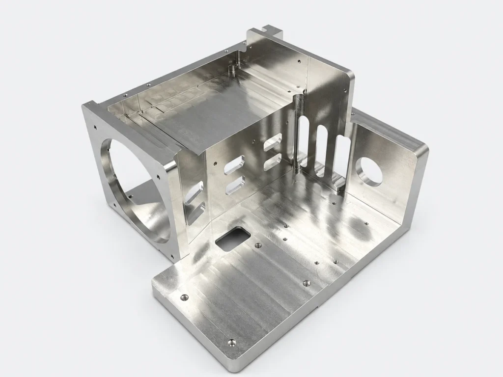
CNC Machined Prototypes
Custom metal and plastic prototype components manufactured by milling and turning, including housings, brackets, shafts and mating parts. Machined features can be combined with specified finishing and assembly operations to complete the prototype.
3D Printed Prototypes
Printed models and components for product development, from individual parts to assembly sets. Depending on the printing process, preparation for delivery may include support removal, cleaning, curing and agreed surface finishing.
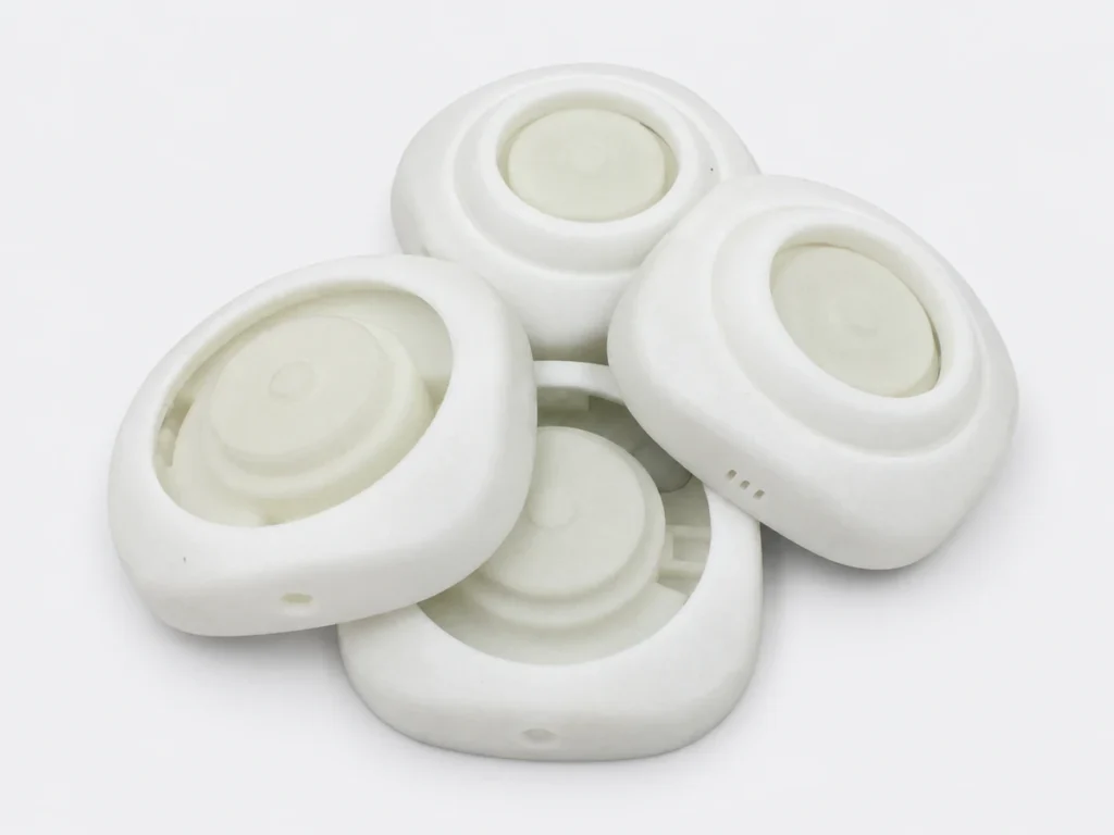
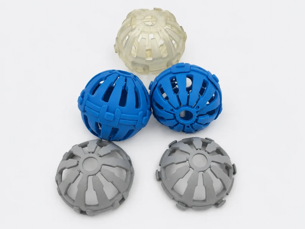
Vacuum Cast Prototypes
Polyurethane prototype sets reproduced from a master pattern using silicone molds. Depending on the selected casting material, projects can include rigid or flexible components, specified colors and surface finishes for product demonstrations and assembly builds.
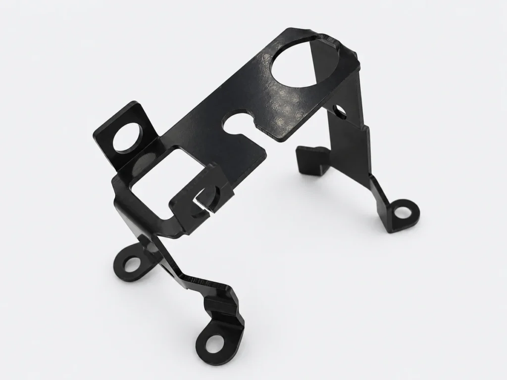
Sheet Metal Prototypes
Custom prototype parts produced through cutting and bending, with hardware installation, joining and finishing where required. The scope can cover individual brackets and panels or multiple components for an enclosure assembly.
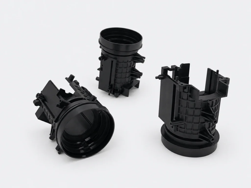
Prototype Injection Molding and Rapid Tooling
Prototype molds and injection-molded samples in the specified resin. The project scope can include mold manufacture, trial molding and sample revisions agreed after review, supporting development from tool construction to molded-part evaluation.
Rapid Prototyping Project Examples
See how SAMSHION combines materials, manufacturing processes and finishing to build prototypes for product development.
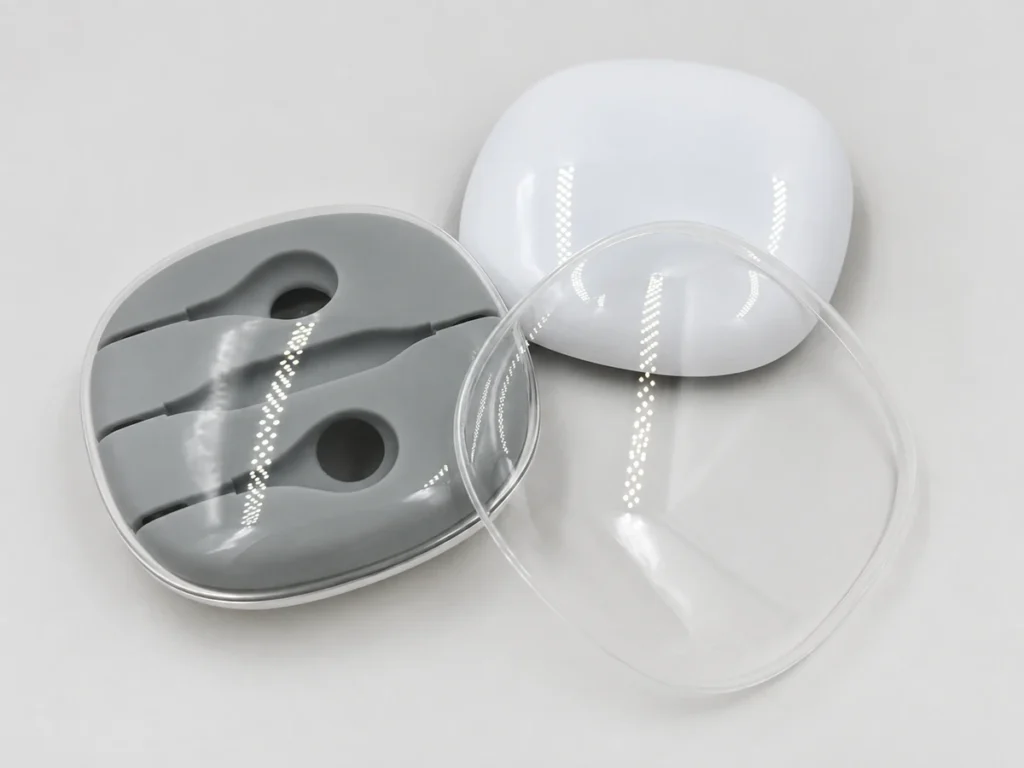
Multi-Material Headphone Case Prototype
Materials and Manufacturing
The prototype was made for reviewing the case structure, component fit and assembled appearance.
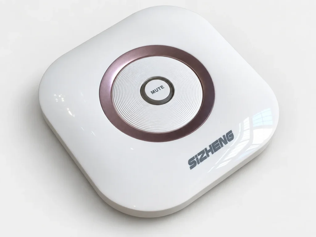
Wireless Charger Prototype
Materials and Manufacturing
The prototype was used to evaluate the housing structure, component fit, assembled appearance and electronic functionality.
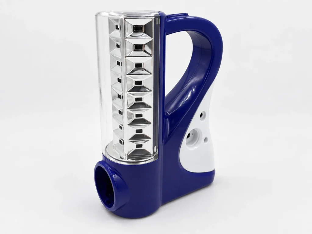
Lighting Prototype
Materials and Manufacturing
The prototype was used to review the housing structure, cover fit and component assembly, together with the appearance of the painted, transparent and plated surfaces.
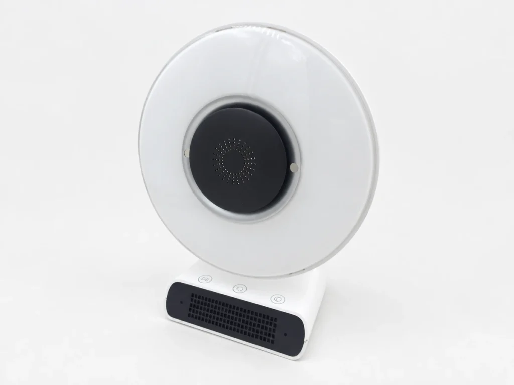
Bluetooth Speaker Prototype
Materials and Manufacturing
The prototype was used to review the structure, component fit and assembled appearance, and to verify electronic functions including Bluetooth connectivity and audio playback.
What Can a Prototype Validate?
A prototype is most useful when the review has a clear purpose. Define what needs to be checked and the conditions it must represent, then use the findings to guide the next design decision.
Form and Space Requirements
Check overall dimensions, proportions and clearance within the intended installation space. A physical model can reveal access restrictions, handling difficulties and interference with surrounding equipment before detailed assembly or performance testing begins.
Fit and Assembly
Check how mating parts locate, fasten and move together. Review hole alignment, interface clearances, fastener access and assembly sequence. Where available, use the actual mating components to identify adjustments needed before the next build.
Functional Performance
Evaluate the functions relevant to the design, such as movement, load response or operation with installed electronics. Define the test conditions and acceptance criteria in advance. Results must be interpreted in light of the prototype’s material, manufacturing process and configuration.
Appearance and User Feedback
Review shape, color, texture, markings and the visibility of joints under the intended viewing conditions. Handling sessions can also reveal issues with grip, control placement and readability. Record feedback against agreed references so revisions address specific concerns.
Manufacturing Feasibility
Use the prototype build to identify features that are difficult to produce, finish or assemble. Findings can guide changes to geometry and specifications. If the production method differs from the prototype method, manufacturing assumptions need to be reviewed again before production.
Pilot Use and Field Feedback
A limited set of prototypes can support evaluation in the intended operating environment. Observe repeated use, installation, maintenance access and unexpected interactions over an agreed trial period. Track feedback by sample and design revision to guide the next development stage.
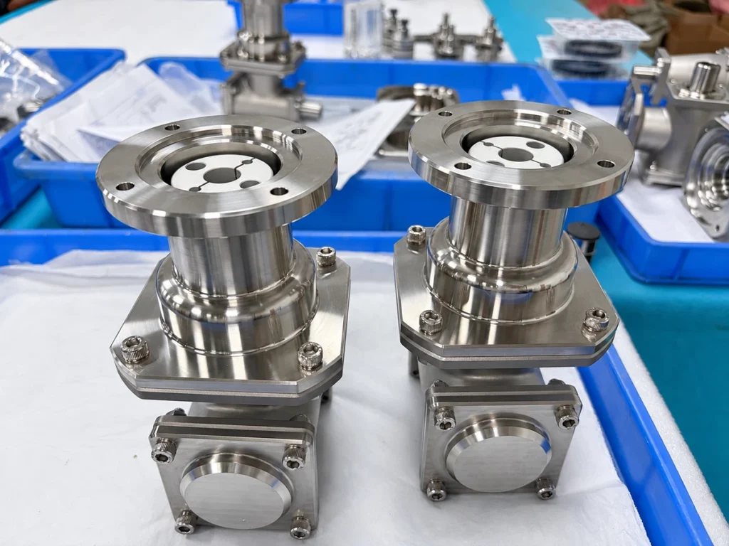
From CAD Files to Prototype Parts
Share Your CAD Files
Send your current 3D CAD files and available drawings, together with the required quantity, material, finish and target delivery date. Tell us what the prototype needs to demonstrate and identify any critical dimensions or mating components.
Review Project Feasibility
We review the files for process suitability and identify missing information or features that need clarification. Questions and proposed design adjustments are discussed with you so the quotation can reflect the intended requirements.
Confirm Scope and Quotation
Confirm the manufacturing process, material, quantity, finish, inspection requirements and delivery schedule. The quotation establishes the agreed scope, including any finishing, assembly or documentation requested for the project.
Prepare for Manufacturing
Following order confirmation, preparation proceeds using the approved design revision. Depending on the selected process, this may include programming, build setup, fixture planning, master patterns or prototype tooling. Outstanding technical details are resolved before the affected work begins.
Produce and Inspect Parts
Parts are manufactured and checked against the agreed requirements. Specified finishing and assembly operations are completed within the project scope. Any discrepancies requiring a decision are communicated so the next action can be agreed.
Deliver and Review
Parts are packed for delivery with any agreed documentation. After your evaluation, share the findings and identify any required changes. The scope, cost and timing of a revised build can then be confirmed before further work begins.
Materials for Rapid Prototypes
Specify the material grade and required condition, not only the material family. Availability and suitability are reviewed for the selected manufacturing process.
Metals
Polymers and Resins
For more material options, explore our manufacturing materials guide. Any proposed substitution should be identified and approved before manufacturing.
Surface Finishes for Rapid Prototypes
Surface finish requirements should identify both the intended appearance and the areas that need protection. Agree the references and finishing scope before work begins.
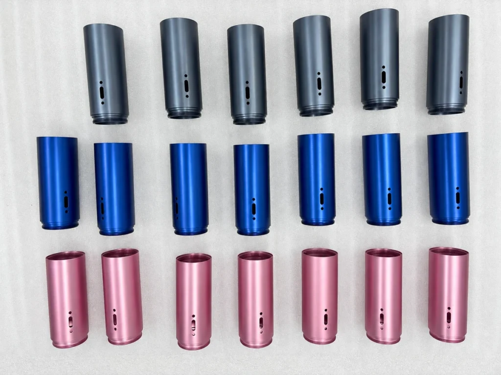
Color and Gloss
Provide a color code or approved sample, and specify the required gloss level. Identify which visible surfaces should match.
Texture and Markings
Identify the areas that need a smooth, textured or polished appearance. Supply artwork and placement details for any printed logos, labels or markings included in the project.
Fit and Masking
Mark threads, holes, mating faces and other fit-critical areas that need masking or dimensional control. Define coating thickness where it affects assembly.
Explore our surface finishing guide for process options. The finish must be compatible with the base material and intended use.
Prototype Design Checklist
Use the CAD model and drawings to make the following details clear before manufacturing.
Mark Critical Dimensions
Identify the dimensions that control fit, movement or alignment. State both feature-specific and general tolerances on the drawing so the inspection requirements are unambiguous.
Show Internal Features
Use section views or detail drawings to explain internal cavities, recessed features and holes that are difficult to interpret from the outside. Include the dimensions needed to define their geometry.
Review Process-Specific Geometry
Review thin walls, internal corners, deep features and access limitations against the intended manufacturing method. Flag features that may need adjustment, and agree any design changes before the build.
Provide Assembly References
Share mating-part models or interface drawings where assembly fit matters. Identify alignment features, fastening points and required clearances so individual components can be reviewed in the context of the complete assembly.
Quality Control for Rapid Prototypes
Prototype inspection focuses on the dimensions, appearance and assembly requirements agreed for the project.
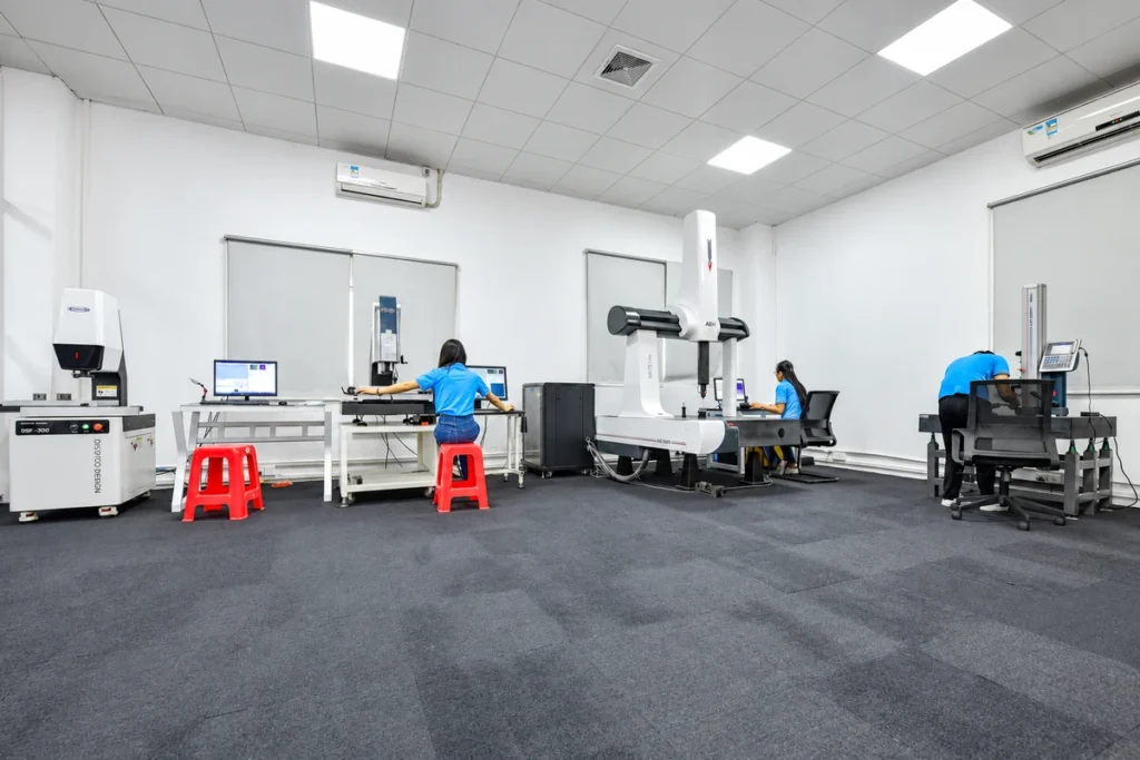
Dimensional Inspection
Critical dimensions and interfaces are checked against the approved drawing, using measurement methods suited to the features and specified tolerances.
Appearance and Assembly
Specified surfaces and finishes are reviewed against the agreed references. Where assembly verification is included, the relevant parts or customer-supplied mating components are used to check fit.
Checks During the Build
For multiple-part or repeated builds, selected features can be checked before the full batch is complete. The inspection timing and scope are established according to project requirements.
Inspection Reports
- Dimensional inspection report
- Appearance inspection report
- Material reports
- CMM reports
- Other agreed documentation
Rapid Prototyping FAQs
Which rapid prototyping process should I choose?
Start with what you need to evaluate: appearance, fit, assembly or function. Send your CAD files, material requirements and quantity, and tell us how the parts will be used. SAMSHION can review the project and recommend a suitable manufacturing route.
How quickly can prototype parts be delivered?
Lead time depends on the selected process, part complexity, material availability, quantity and finishing requirements. Share your required arrival date when requesting a quotation so production and shipping time can be considered together. The schedule is confirmed for the agreed project scope.
Can I order just one prototype?
Yes. SAMSHION accepts single-part orders and has no minimum order quantity. The quotation depends on the process, setup, material and finishing involved, so the unit cost of a single prototype may differ from that of a larger batch.
What files should I send for a quotation?
We accept STEP, IGES, STL and native CAD files, as well as PDF, DWG and DXF drawings. Include the quantity, material, finish and required date. For dimension-critical features, provide a drawing that identifies tolerances and inspection requirements.
Can my prototype use the final production material?
Where the chosen process supports the specified grade, yes. Include the exact material designation if production-material testing is important. A printed or cast substitute should not be treated as equivalent simply because it looks similar; any proposed alternative should be identified and agreed before manufacturing.
Can you match a specific color, finish or logo?
Painting, anodizing and printed markings can be included where compatible with the part material. Share a color reference, approved sample or artwork, and identify the areas to be finished. Color, gloss and texture acceptance should be agreed in advance.
How should I specify prototype tolerances?
Mark the dimensions that control fit, movement, alignment or sealing, and provide the relevant mating-part information. Include general tolerances for the remaining features. If you are unsure, flag the interfaces that matter so the requirements can be reviewed before the build.
Can prototype work continue into low-volume production?
Yes. Prototype feedback can be used to plan a repeat build or low-volume production. The next stage may use a different material, process or tooling approach, so drawings, inspection requirements, quantities and pricing should be reviewed before proceeding. Prototype approval alone does not approve a changed production process.
Start Your Rapid Prototyping Project
Send your CAD files, required quantity and project requirements. Our team will review the manufacturing options and prepare a project-specific quotation.