
CNC Turning Services for Precision Custom Parts
Manufacture shafts, sleeves, bushings, pins, threaded bodies and other components built around a rotational axis. For parts that also contain flats, slots, cross-holes or multi-directional features, SAMSHION can combine turning with an appropriate secondary machining route.
- Standard CNC turning and C-axis live-tool machining
- Metal and engineering-plastic parts from prototype to repeat orders
- CMM and calibrated dimensional inspection available
What Is CNC Turning?
CNC turning is a subtractive machining process in which the workpiece rotates while a programmed cutting tool removes material. It is well suited to components built primarily around a central axis, including shafts, sleeves, bushings, pins, flanges and threaded bodies. Common turned features include outside and inside diameters, bores, shoulders, tapers, grooves and threads.
When a turned component also requires flats, slots, radial holes, mounting faces or features approached from different directions, SAMSHION reviews the complete geometry to select standard turning, C-axis live tooling or a combined route using separate CNC milling or 5-axis machining. The route depends on tool access, datum relationships, quantity, tolerance and inspection requirements. Related processes are available through our broader CNC machining services.
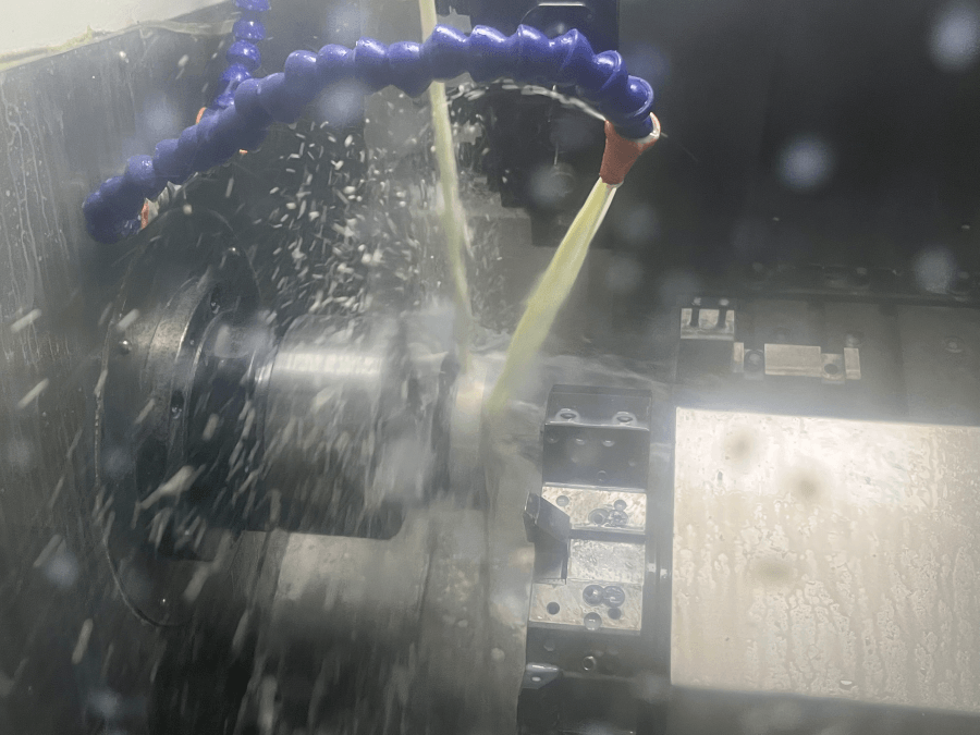
CNC Turning Equipment and Practical Capacity
SAMSHION operates CNC turning centers for conventional turning, with selected machines equipped for C-axis positioning, live-tool operations and bar-fed production. The figures below describe separate equipment limits and should not be interpreted as one guaranteed combined work envelope.
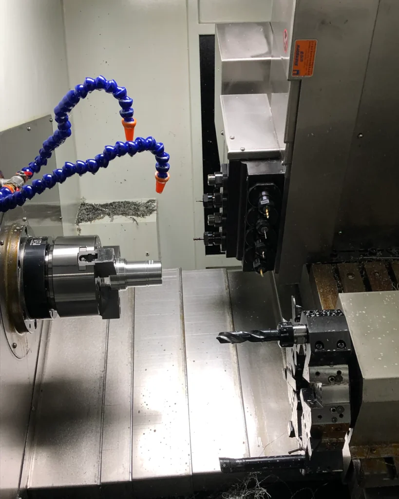
Maximum diameter, maximum length and bar-through capacity are separate machine limits. A component approaching one limit may not be feasible at another limit within the same setup.
Choose the Right CNC Turning Route
Standard CNC Turning
Use this route when the important features share a common rotational axis and fixed turning tools can reach them. It is the most direct option for primarily cylindrical components without substantial off-axis geometry.
C-Axis Turning with Live Tooling
Use C-axis positioning and powered tools for selected holes, flats or slots arranged at defined angular positions. This route suits limited secondary features that remain accessible in the turning setup. It is not the same as 5-axis machining.
Turning Plus CNC Milling
Use a separate CNC milling operation when the turned body contains larger pockets, multiple mounting faces or off-axis features beyond the practical scope of live tooling. Turning and milling remain distinct operations, so datum transfer between setups must be controlled.
Turning Plus 5-Axis Machining
Use a combined turning and 5-axis machining route when non-rotational geometry spans several orientations, requires difficult holder clearance or includes surfaces unsuitable for fixed-direction machining. This combines separate turning and 5-axis operations and does not imply simultaneous 5-axis cutting or one machine setup.
Select the least complex route that can reliably produce the required geometry. Standard turning, C-axis live tooling, separate milling and 5-axis machining are different process choices and should not be used interchangeably.
Why Choose SAMSHION for CNC Turning?
Manufacturing Risk Review
Thin walls, deep bores, unsupported sections, interrupted cuts, thread runouts and difficult deburring can change the turning strategy. These risks are identified before programming. Any proposed geometry change is returned for approval rather than introduced during production without confirmation.
Datum and Workholding Strategy
Rotational features remain related only when centerlines, locating surfaces and clamping points are planned together. The setup strategy considers chucking length, bore access, part support, tool clearance, parting location and datum transfer to any later machining operations.
Controlled Prototype-to-Repeat Transfer
After a prototype is approved, repeat orders can retain the released program, setup information, tooling requirements, inspection checkpoints and drawing revision. A change to the geometry, material or finish triggers a new review instead of being carried into the previous process without evaluation.
Confirmed Production Scope
The quotation records the confirmed machining route, material and finish, production quantity, inspection deliverables and delivery schedule. Open assumptions are returned as clarification questions so production begins from an agreed scope rather than a best-case interpretation.
Real CNC Turning Project Examples
These six examples show how CNC turning was applied alone or combined with C-axis live tooling, separate milling or 5-axis machining for different component geometries. Each slide records confirmed facts from a specific project and should not be interpreted as a universal tolerance or process guarantee.
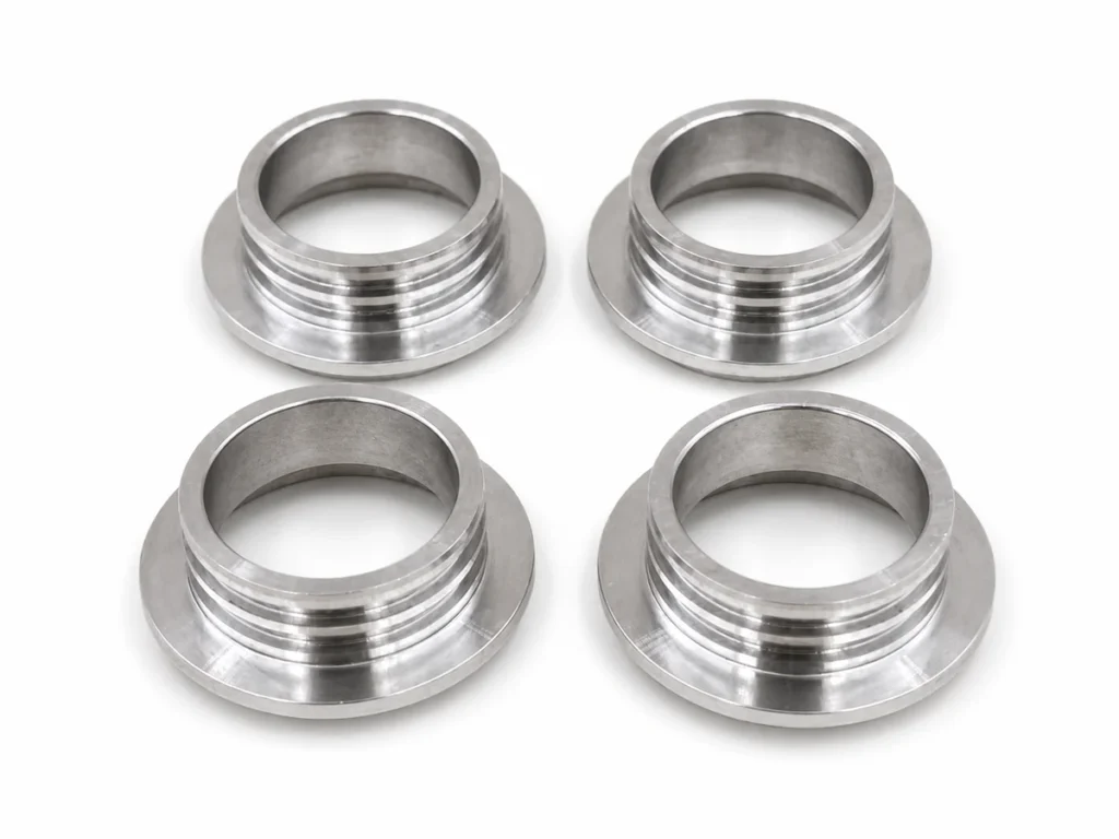
Standard CNC Turning for 6061-T6 Flanged Ring Components
These low-volume aluminum 6061-T6 components were produced by standard CNC turning and supplied with an as-machined finish. The rotational geometry includes a through bore, stepped outside diameters, external annular grooves and a flange face.
Because the main features share a common turning axis, standard CNC turning provided a direct manufacturing route without unnecessary secondary milling. Selected dimensions were inspected according to the controlled drawing using outside micrometers, pin gauges and a height gauge.
Small-Batch Turn-Mill Machined 6061-T6 Connectors
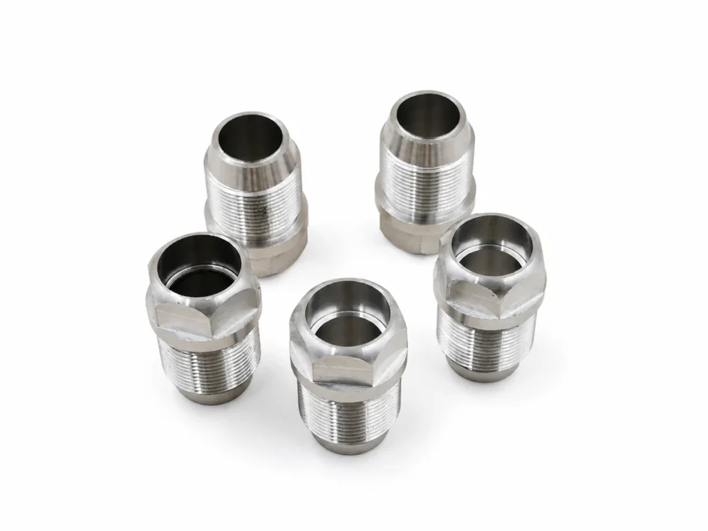
This example shows two one-piece connector geometries produced in small batches from 6061-T6 aluminum and supplied with an as-machined finish. A combined CNC turning and milling route was used to produce both the rotational and non-rotational features on a turn-mill platform.
Turning produced the external threads, unthreaded bores, stepped outside diameters and tapered transitions. Milling produced the integrated hexagonal wrench sections. Combining both processes reduced the need for transfer to a separate standalone milling machine and helped maintain the relationship between the turned and milled features.
Inspection followed the controlled drawing. External threads were checked with the appropriate thread gauge, selected outside diameters with outside micrometers, applicable bore dimensions with pin gauges, and selected axial or height-related characteristics with a height gauge.
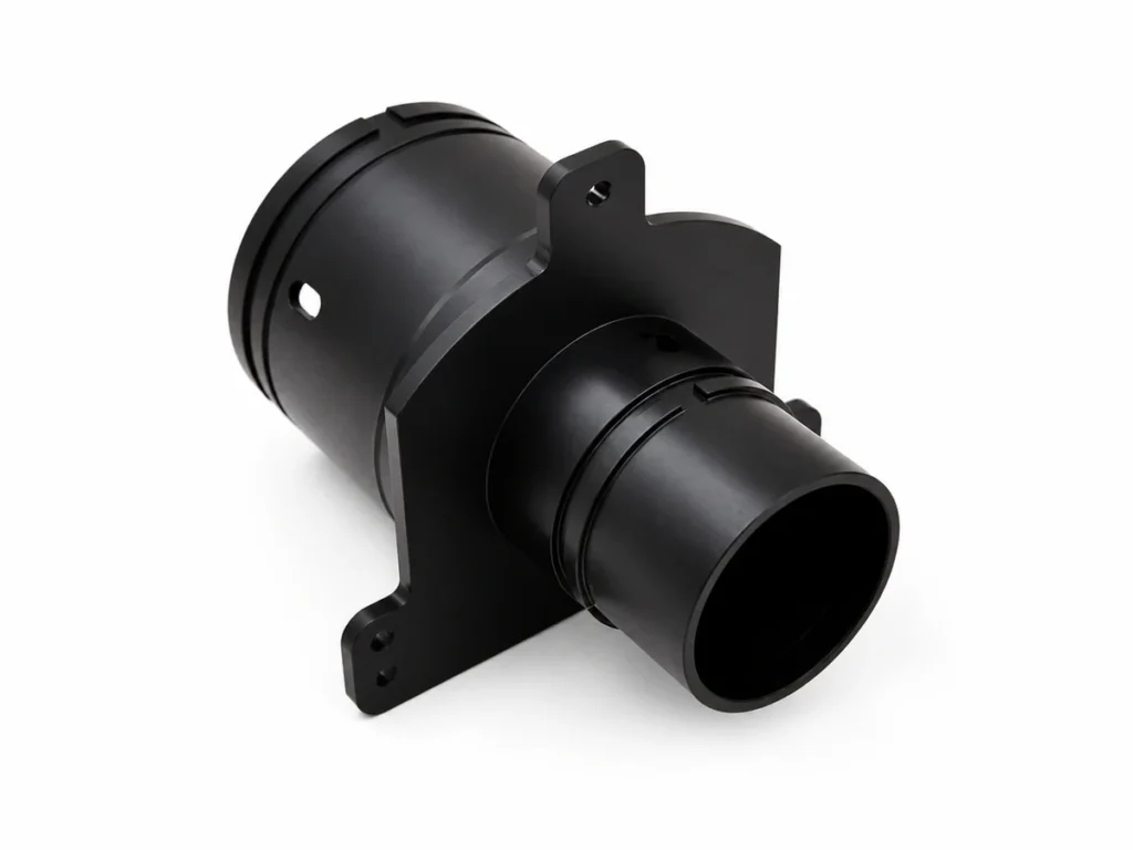
Small-Batch CNC-Turned and 5-Axis Machined 6061-T6 Housing
This small-batch component was machined as one complete part from solid 6061-T6 aluminum using a combination of CNC turning and 5-axis machining, followed by black anodizing.
CNC turning established the large internal bore and the primary coaxial cylindrical surfaces, shoulders and annular grooves. Five-axis machining was used for the non-axisymmetric mounting flange, projecting mounting features and hole pattern.
Critical drawing requirements included the internal-bore size, coaxiality between the specified rotational features, mounting-hole position and flange flatness. CMM inspection was used for applicable bore and geometric relationships. Outside micrometers, pin gauges and thread gauges were used for the corresponding dimensional and functional checks.
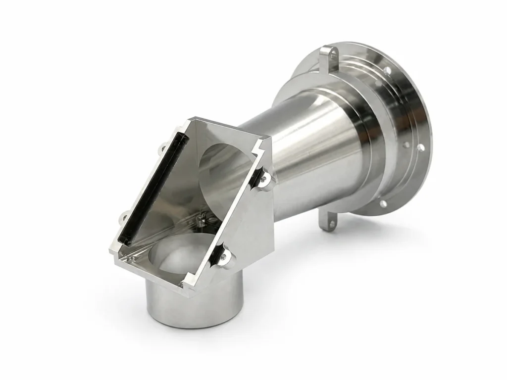
Small-Batch CNC-Turned and 5-Axis Machined 6061-T6 Multi-Feature Housing
This small-batch component was machined as one complete part from solid 6061-T6 aluminum and supplied with an as-machined finish.
CNC turning established the primary cylindrical geometry, including the main body, large internal bore and rotational reference surfaces. Five-axis machining was then used for the non-axisymmetric features, including the circumferential hole pattern on the end flange, side-facing port, open rectangular cavity, mounting lugs and holes approached from different directions.
Critical drawing requirements included the internal-bore size, coaxiality between the specified rotational features, hole position, perpendicularity, flatness and profile. CMM inspection was used for the applicable dimensional and geometric relationships. Pin gauges and thread gauges provided functional verification for the specified holes and threaded features.
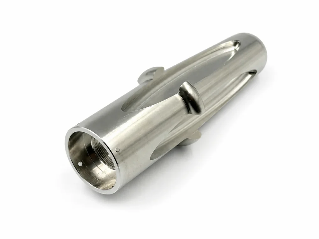
Prototype 6061-T6 Component Produced by CNC Turning and C-Axis Live Tooling
This prototype component was machined from 6061-T6 aluminum and supplied with an as-machined finish.
CNC turning established the slender cylindrical body, internal bore, internal thread and primary rotational reference features. C-axis live tooling was then used for the non-axisymmetric geometry, including the circumferential elongated slots or windows, external profile features and radial holes.
Critical drawing requirements included the internal-bore size, internal thread, coaxiality between the specified rotational features, slot position and the profile of the controlled external geometry. CMM inspection was used for the applicable dimensional and geometric characteristics, while the internal thread was verified with the appropriate thread gauge.
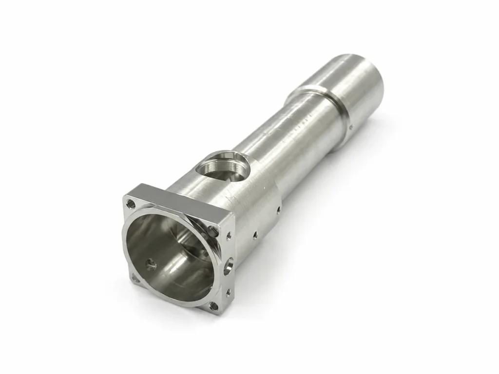
Prototype CNC-Turned and 5-Axis Machined 6061-T6 Aluminum Component
This prototype was machined as one complete component from solid 6061-T6 aluminum and supplied in the natural as-machined condition. CNC turning established the long cylindrical body, internal bore and primary rotational reference features. Subsequent 5-axis machining produced the square front flange, side threaded hole and other holes approached from different directions.
Using turning and 5-axis machining allowed the rotational geometry and multi-directional features to be produced through a controlled manufacturing route. The process does not imply simultaneous 5-axis cutting or completion in a single setup.
How CNC-Turned Features Are Inspected
Inspection tools are selected according to the characteristic being verified rather than the component as a whole. Size measurement, functional gauging, geometric verification and surface-texture evaluation answer different inspection questions.
CMM, pin gauges and thread gauges do not provide interchangeable results. Functional gauges normally provide an acceptance decision, while a numerical inspection report requires an agreed measurement and reporting method.
For additional guidance, review our CNC machining inspection guide.
Materials for CNC Turned Parts
Turning behavior can vary substantially between grades within the same material family. The summaries below highlight the main factors affecting chip control, tool load, surface condition and dimensional stability. Specify the exact grade, temper, hardness or plastic formulation required for your component. For a broader comparison, review our manufacturing materials guide.
Aluminum
Aluminum supports efficient turning of diameters, bores, grooves and threads. However, alloy and temper still affect strength, chip formation, surface appearance and dimensional stability. Aluminum 6061-T6 is commonly selected for general-purpose machined components. Sharp tooling and effective chip evacuation help limit built-up edge and protect fine turned surfaces.
Key turning considerations: alloy and temper, thin-wall movement, chip evacuation and cosmetic tool marks.

Stainless Steel
Stainless steel is selected where corrosion resistance, strength or temperature performance is important. Machinability varies considerably between grades. Some produce long chips, while many can work-harden if the tool rubs instead of cutting. Stable tool engagement and heat control are especially important for deep bores, grooves and threads.
Key turning considerations: exact grade, work hardening, cutting heat, chip control and tool wear.

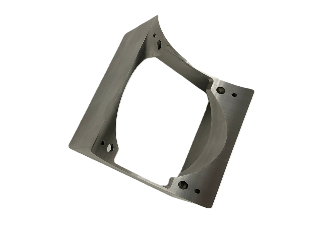
Carbon and Alloy Steel
Carbon and alloy steels cover a broad range of strength, wear resistance and heat-treatment response. Hardness, surface scale, prior heat treatment and any planned post-machining treatment can change cutting load, tool wear and dimensional behavior. The specified material condition is therefore as important as the grade name.
Key turning considerations: hardness and condition, tool wear, heat-treatment sequence and possible dimensional movement.
Brass and Copper Alloys
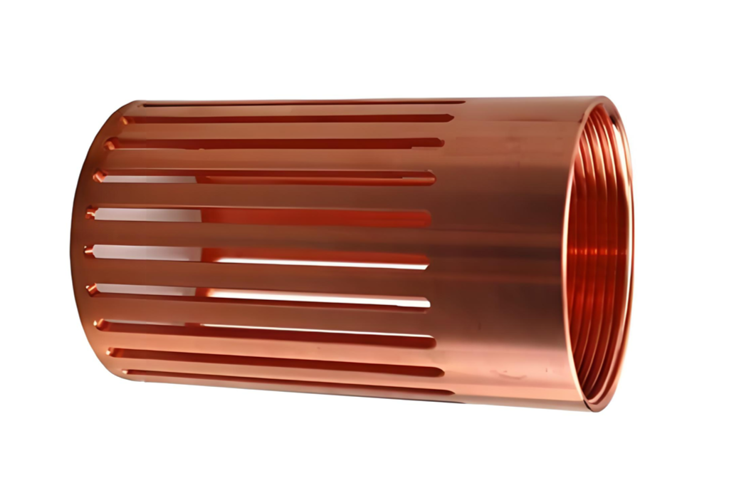
Brass and copper alloys should not be treated as having the same machining behavior. Many brass alloys can produce controlled chips and clearly defined features, while high-copper materials may be more ductile and prone to smearing, burrs or cosmetic marking. Alloy selection also affects strength, conductivity and corrosion performance.
Key turning considerations: exact alloy, burr formation, chip behavior and protection of visible surfaces.
Titanium
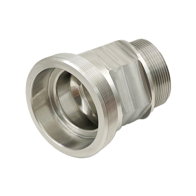
Titanium combines a high strength-to-weight ratio with good corrosion resistance, but it retains cutting heat near the tool and can accelerate tool wear. Rigid workholding, controlled engagement and effective coolant delivery are important, particularly around thin walls, grooves and threaded features.
Key turning considerations: cutting heat, tool wear, workholding rigidity and longer machining time than comparable aluminum parts.
Engineering Plastics
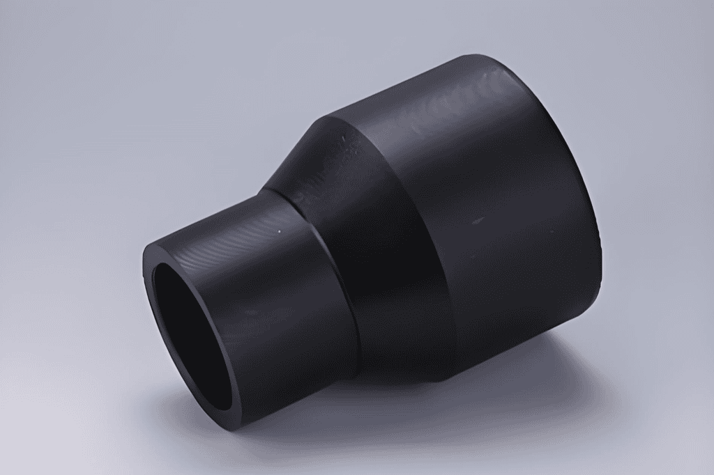
Engineering plastics can turn cleanly, but their thermal expansion, moisture response, internal stress and clamping sensitivity differ from metals. Cutting heat or excessive chuck pressure can affect bore size, roundness and post-machining stability. Resin grade, reinforcement and required conditioning should be identified when they affect function.
Key turning considerations: exact resin grade, operating temperature, moisture conditioning, clamping force and burr control.
Surface Finishes for CNC Turned Parts
Surface finishing can change the appearance, corrosion behavior, wear response and texture of a CNC-turned part. On rotational geometry, an added finish may increase outside diameters, reduce bore size, change thread engagement or cover sealing and electrical-contact surfaces. The samples below illustrate common finish categories; the selected process must suit the substrate and the surfaces that need to remain controlled.
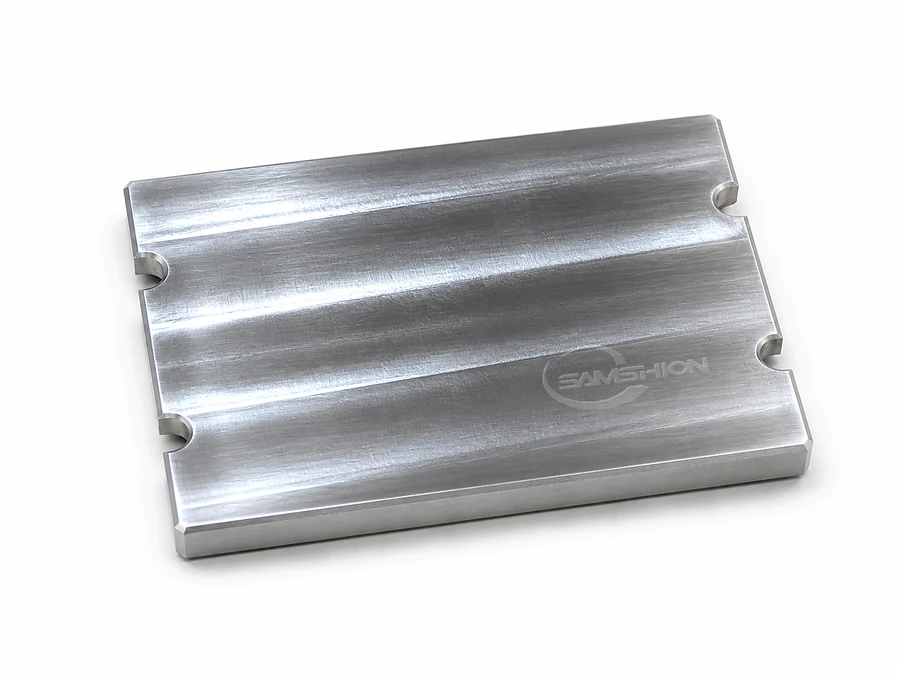
As Machined
After turning, parts are deburred and cleaned while the normal feed pattern remains visible on cylindrical and faced surfaces. This is generally the most direct option when no additional coating or cosmetic treatment is required. “As machined” does not establish one universal roughness value, so any functional surface requirement must be specified separately.
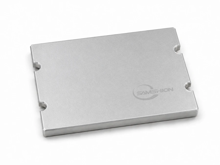
Bead Blasting
Bead blasting creates a more uniform matte appearance and can reduce the visual contrast of light turning marks, although deeper feed lines may remain. Precision diameters, threads, sealing lands and bores may require protection. Media entrapment should also be considered for blind holes and internal passages.
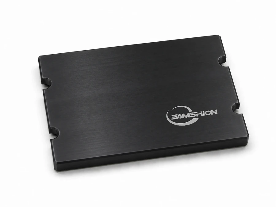
Anodizing
Anodizing is used on compatible aluminum alloys to improve corrosion behavior and provide decorative or wear-resistant surfaces. The anodizing type, color, sealing condition, electrical-contact areas and masking requirements should be defined. Coating growth can change outside diameters, bore sizes and thread engagement, so masking or pre-finish dimensional allowance may be required.
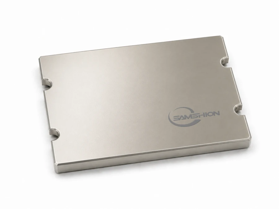
Electroless Nickel Plating
Electroless nickel plating deposits a comparatively uniform metallic layer that can improve corrosion and wear resistance. On turned geometry, the deposited layer increases outside diameters while reducing bore size and available thread clearance. Critical fits, threads, sealing surfaces and masked areas should therefore be identified before plating.
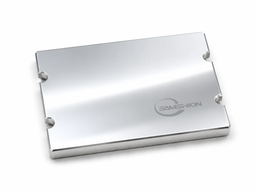
Polishing and Brushing
Polishing creates a smoother and more reflective surface, while brushing produces a controlled directional texture. On round components, the required direction and its transition around shoulders, grooves and other features should be defined. When appearance consistency is important, identify the visible surfaces, finish level and any approved physical reference sample.
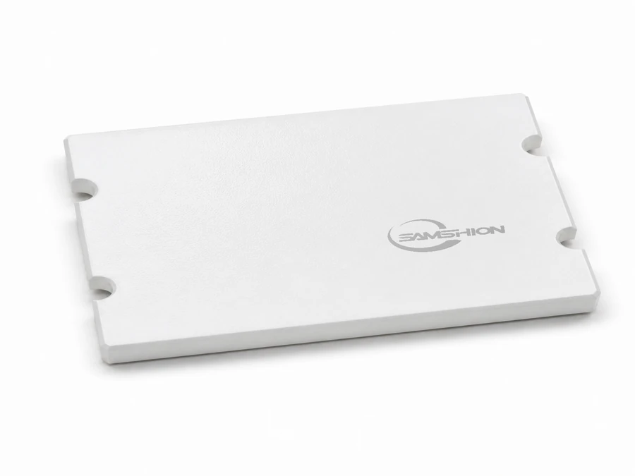
Powder Coating
Powder coating forms a durable colored polymer layer on compatible metal parts and is available in different colors, textures and gloss levels. Because the coating is comparatively thick, close fits, bores, threads, sealing lands and electrical grounding areas normally require masking or dimensional allowance. Coverage may also vary inside recesses and around complex profiles.
The photographs show standardized finish samples for visual comparison. Final color and texture can vary with the alloy, starting surface, geometry, batch and process conditions. When appearance is critical, identify the cosmetic surfaces, masked areas and approved physical sample; screen color alone should not be used as the final acceptance reference.
CNC Turning Design Guidelines
Good turning design begins with the rotational reference: which diameter or bore establishes the part axis, which face locates the assembly and which features must remain related after any secondary operation. The following guidelines focus on geometry decisions that affect tool rigidity, workholding, chip evacuation and functional performance.
Define Datums and Functional Relationships
Use a controlled 2D drawing to establish the functional axis, locating face and feature relationships that affect assembly. A bore and an outside diameter are not automatically coaxial simply because they share the same nominal centerline in the 3D model. Define the applicable datum references and geometric tolerances instead of relying only on decimal-place precision.
Keep Internal Features Accessible
Deep bores, narrow internal grooves and shoulders behind a small opening may require long, flexible tools and make chips difficult to remove. When function permits, enlarge the access diameter, reduce unnecessary depth, add a practical relief or allow machining from the opposite end. Internal geometry should also leave a workable route for measurement or functional gauging.
Use Standard Threads and Practical Reliefs
Identify the thread standard, nominal size, pitch, class, handedness and required usable length. For blind threaded holes, separate the usable thread length from the drill depth. Provide an appropriate lead-in and tool runout or relief instead of requiring a complete thread form directly against a blind shoulder.
Avoid Thin Unsupported Walls
Thin tubes, flanges and walls can deflect under chucking force and move after material is removed. Increase wall thickness or shorten unsupported length where possible. If a thin section is unavoidable, allow temporary support stock or a later finishing operation and define dimensional acceptance in the unclamped condition.
Specify Surface Finish Only Where It Matters
Apply roughness or cosmetic requirements only to surfaces performing a sealing, bearing, sliding or visible function. A blanket fine-finish requirement can add unnecessary machining without improving the component. Surface roughness and visual appearance are different requirements and should be specified separately.
Plan Cross-Holes, Flats and Slots
Show the angular orientation of cross-holes, flats and slots relative to a functional datum. Provide a clear tool approach and consider drill breakout, intersecting features, burr access and remaining wall thickness. Limited off-axis features may suit C-axis live tooling, while dense or multi-directional geometry may require a separate milling operation.
Clarify Edge and Burr Requirements
Replace a general “deburr all edges” note with a defined edge break where edge size affects function. Identify internal intersections, cross-holes and fluid passages that require controlled burr removal. Avoid specifying both a perfectly sharp edge and a mandatory edge break at the same location.
Use Realistic Tolerances
Reserve close tolerances for features that control fit, alignment or performance. Apply an appropriate general tolerance to noncritical dimensions, then define critical sizes and geometric relationships explicitly. Tightening every dimension can increase machining and inspection effort without improving function. Review our CNC machining tolerance guide for further guidance.
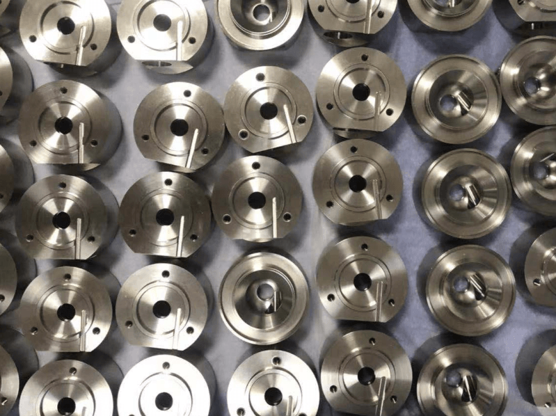
Quality Control for CNC Turned Parts
Quality control for a turned part follows the production sequence rather than relying on one final measurement. The control plan separates setup approval, monitoring of changing process conditions, verification after secondary operations and release of the finished order. For the broader management framework, review our quality assurance and inspection approach.
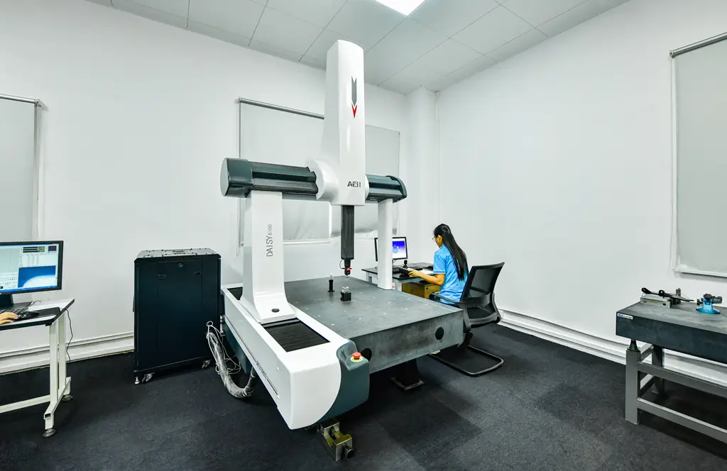
Setup and First-Off Verification
A representative first-off part is checked after the workholding, tools and offsets have been established. Verification focuses on the features that confirm the setup, such as the primary rotational references, selected diameters and bores, axial shoulders, overall length, threads and any controlled relationships to secondary features. Required corrections are completed before the remaining batch continues.
Control of Process Drift
Characteristics that may change with insert wear, thermal stabilization, bar-stock variation, chip accumulation or offset changes are monitored during machining. Checkpoints are placed where they can identify a developing change before it affects the remaining operations. The frequency is selected from the behavior of the process and the importance of the applicable characteristic rather than from one universal sampling rule.
Verification After Secondary Operations
Parting, reclamping, secondary milling, heat treatment and surface finishing can change features that were correct earlier in the process. Applicable diameters, bores, threads, sealing surfaces and datum relationships are therefore rechecked after the operation that can affect them. Acceptance should represent the delivered condition when coating, blasting or another finish changes the final surface.
Final Release and Project Records
Final release confirms the required dimensional characteristics, visual condition, edge and burr condition, finish, quantity and packaging status. Agreed inspection records and certificates are matched to the applicable order and part revision before shipment. Any unresolved discrepancy must be addressed before the order is released.
From Quote to Finished CNC Turned Parts
Upload Files
Send the STEP model and any controlled drawing needed to define threads, fits, GD&T or finishing requirements.
Clarification and DFM
Questions, manufacturability concerns and proposed changes are returned for review. No proposed design change is released without approval.
Approve the Quote
Production begins after the quotation, confirmed scope, delivery schedule and requested project records have been approved.
Process Planning
Programs, workholding, tool sequence and first-off inspection points are prepared for the approved design revision.
Machining and In-Process Checks
Parts are machined with first-off and in-process checks completed at the planned production stages.
Final Release and Shipment
Finished parts receive final inspection, cleaning and protective packaging. Agreed reports and certificates are included with the shipment.
CNC Turning FAQs
What files should I send for a CNC turning quote?
Send a STEP file or another agreed 3D solid format to define the component geometry. Include a controlled 2D drawing when threads, fits, GD&T, surface roughness, finishing or inspection requirements affect acceptance. The submission should identify the units, drawing revision, required material grade and condition, quantity and required finish.
What size CNC-turned parts can SAMSHION machine?
Current equipment limits include a maximum turning diameter of up to Ø350 mm, a maximum turning length of up to 1000 mm and bar-through capacity of up to Ø45 mm. These are separate machine limits rather than one guaranteed combined work envelope. Practical capacity also depends on chucking length, unsupported length, workholding, tool clearance and feature access.
Can SAMSHION produce prototypes and repeat orders?
Yes. CNC turning can support prototype quantities, low-volume batches and repeat production. Prototype results may establish the workholding, tooling sequence and control points used for later quantities. Repeat orders should reference the approved design revision; changes to geometry, material, finish or acceptance requirements require a new review.
When is C-axis live tooling used?
C-axis positioning and powered tools are suitable when a primarily turned component also requires selected axial or radial holes, flats or slots at controlled angular locations. These features must remain accessible in the turning setup. C-axis live tooling is not the same as 5-axis machining, and extensive multi-directional geometry may require a separate milling operation.
Can you machine internal and external threads?
Internal and external threads can be machined when their size, form, depth and access suit the selected process. Specify the thread standard, nominal size, pitch, class, handedness, usable length and any required lead-in or relief. Appropriate thread gauges can be used for functional verification when the gauge requirement is included in the agreed inspection scope.
What tolerances can CNC turning achieve?
There is no single tolerance that applies to every turned dimension. Practical capability depends on feature size, material, unsupported length, wall thickness, workholding, process sequence, finishing and measurement method. Apply close tolerances only to features that control fit or function and define the relevant datum relationships. Review our CNC machining tolerance guide for additional guidance.
How are CNC-turned parts inspected?
The method is selected according to the characteristic being verified. Outside micrometers may be used for accessible diameters, pin gauges for suitable bores, thread gauges for specified threads, height gauges for applicable face relationships and CMM inspection for accessible dimensional or geometric relationships. Surface roughness can be evaluated with a roughness tester where specified. Our CNC machining inspection guide explains these methods in more detail.
How can I reduce the cost of a CNC-turned part?
Keep the primary geometry around a common rotational axis, use standard material and thread specifications, provide practical tool access and avoid unnecessary deep bores, thin unsupported walls or nonstandard reliefs. Apply close tolerances and fine surface requirements only where they protect function. For suitable repeat components, bar-fed production or completing limited secondary features with C-axis live tooling may reduce handling.
Start Your Custom CNC Turning Project
Send us your CAD files and project requirements for a manufacturing review. We evaluate the rotational geometry, secondary milled features, material, quantity, tolerances, surface finish and inspection scope before confirming the CNC turning route, feasibility, lead time and quotation.