GD&T can make a CNC drawing easier to manufacture when it clearly describes how the part functions. It can also make a quotation uncertain when datum references are missing, controls conflict or every surface receives a tight profile requirement.
The supplier does not need less information. The supplier needs the right information: a stable datum reference frame, functional tolerance zones, basic dimensions and an inspection scope that can be executed on the actual part. For standard tolerances by process, see our CNC machining tolerance chart.
Key Takeaways
- Choose datums from functional and stable part interfaces.
- Use position to control feature location within a datum reference frame.
- Use profile where surface form and location must be controlled together.
- Avoid duplicate plus/minus dimensions that conflict with geometric controls.
- State the applicable drawing standard and required inspection evidence.
Why Datums Matter Before the First Toolpath
Datums establish the coordinate system used to orient dimensions and geometric tolerances. A primary datum should generally be stable enough to support repeatable setup and inspection. A tiny flexible tab may exist in CAD but make a poor manufacturing reference. The drawing should identify the governing standard; for ASME-based drawings, use ASME Y14.5 Dimensioning and Tolerancing as the authoritative reference rather than relying on informal interpretations.
The datum sequence should reflect how the part locates in assembly. Manufacturing may use temporary process datums, but the final features still need to relate to the functional drawing datums. See our CNC fixturing and setup guide.
Position Controls Location More Clearly
Position is commonly applied to holes, pins and other features of size. Basic dimensions define the theoretically exact location, while the feature control frame defines the allowable tolerance zone relative to datums. See our CNC production machining.
Do not add plus/minus location dimensions that create a second competing requirement. Clarify material-condition modifiers when they are functionally intended.
Profile for Complex Surfaces
Profile can control the form, orientation and location of a surface within a defined zone. It is useful for cast or machined contours, sealing paths and complex surfaces, but it should be applied with a clear datum structure and coverage.
A profile callout across the entire part may create expensive inspection when only a local interface is functional. Use ‘all around’ or ‘all over’ only when that is truly the design intent.
Runout, Flatness and Perpendicularity
Runout relates rotating surfaces to a datum axis and is often relevant to shafts, bearing seats and sealing diameters. Flatness is a form control and does not require a datum. Perpendicularity controls orientation relative to a datum. See our CNC turning services.
Selecting the correct control avoids stacked requirements and makes inspection more direct.
Connect GD&T to the Inspection Plan
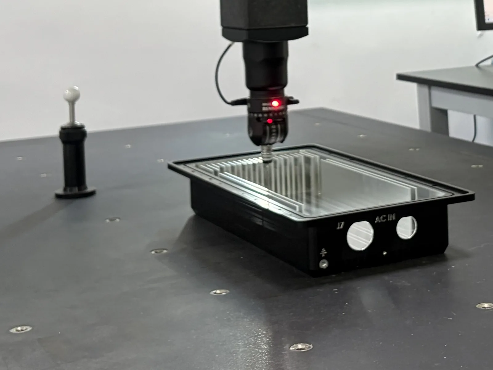
A feature control frame is useful only when the measurement method can realize the datum setup and access the controlled surface. CMM, vision, scanning, functional gauges and manual methods have different strengths.
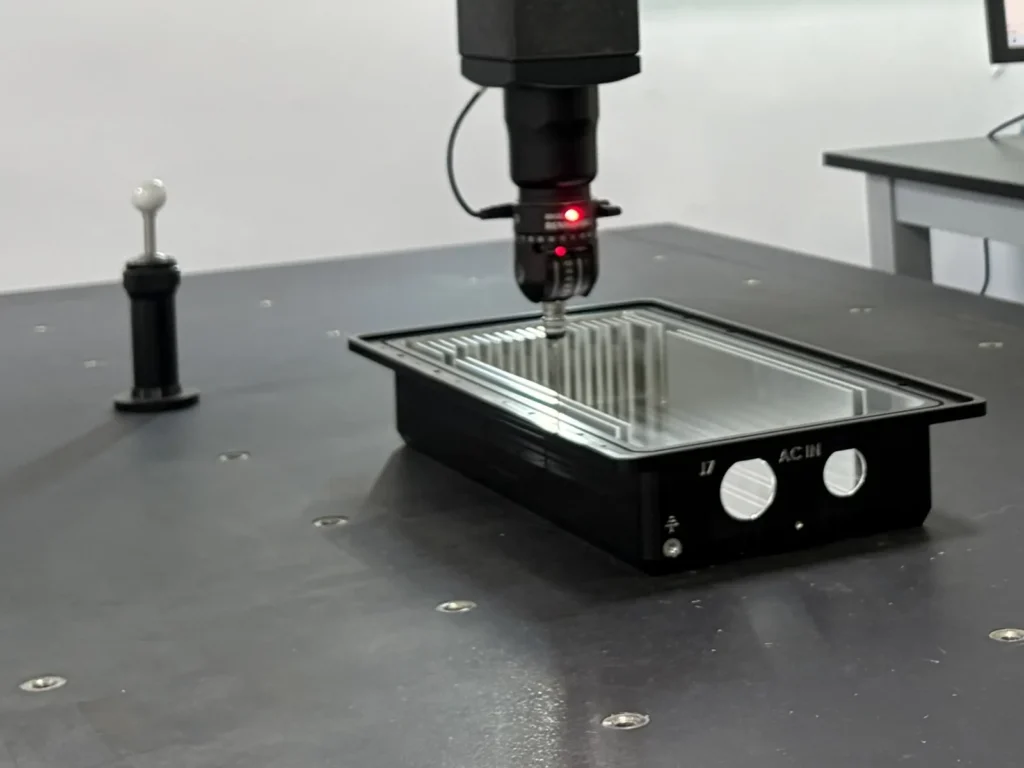
For quotation, identify whether a full first-article report, selected critical dimensions or a certificate of conformance is required.
Drawing Review Checklist
- Applicable GD&T standard and drawing revision
- Stable primary, secondary and tertiary datums
- Basic dimensions for controlled feature locations
- No conflicting duplicate dimensions
- Inspection report scope and customer-supplied gauges
How We Handle GD&T Drawings at SAMSHION
- Standards: most drawings we receive use ISO tolerancing; ASME Y14.5 drawings are less common. We work to the standard stated on the drawing, so please state it.
- General tolerances: dimensions without a tolerance follow ISO 2768-mK by default, which we confirm with each customer before production. See our ISO 2768 tolerances chart.
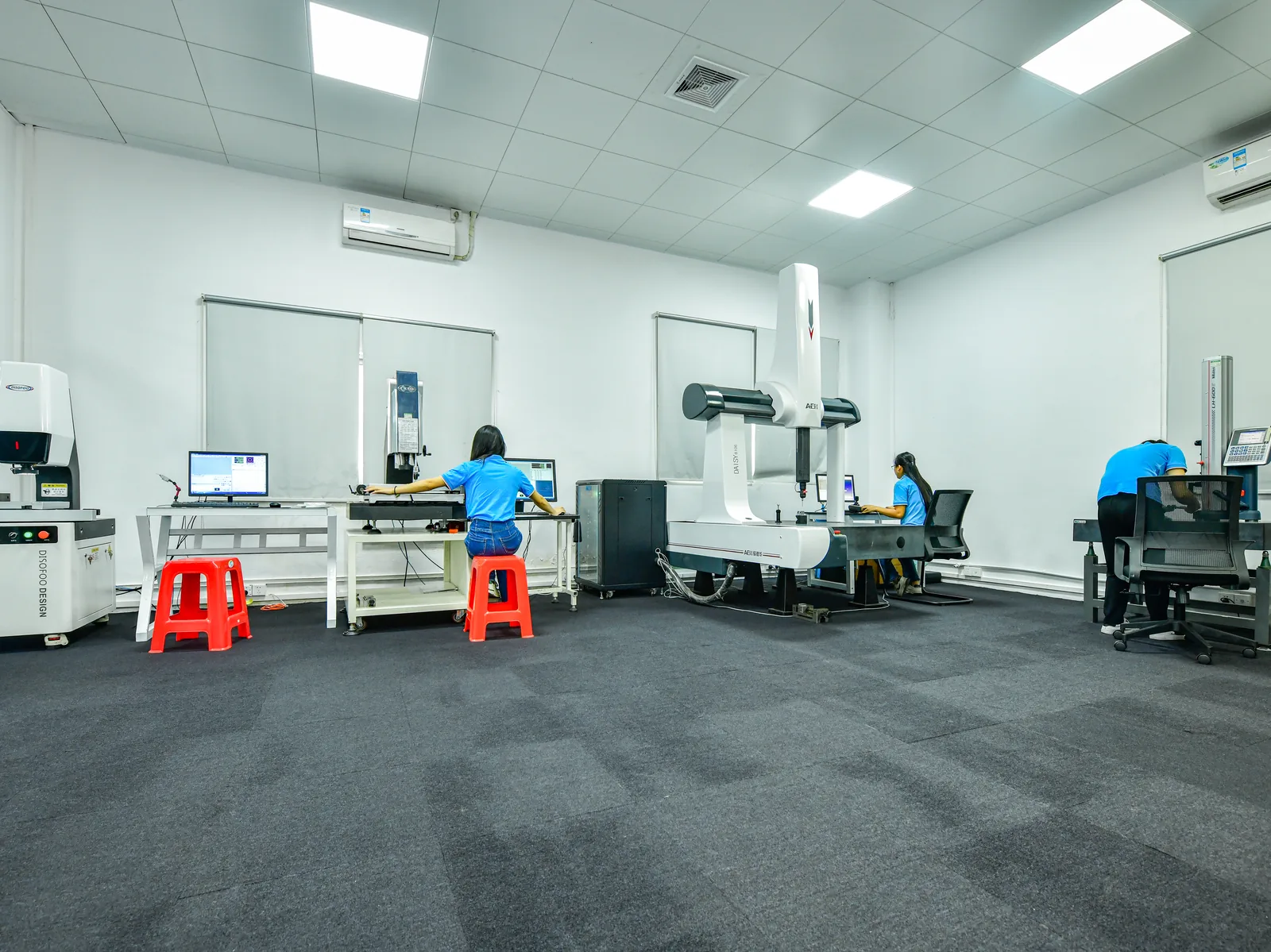
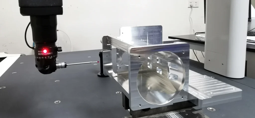
- Inspection: each dimension is checked with the most suitable tool. Position, profile, flatness, perpendicularity and other GD&T requirements are measured on our CMM, set up from the datums on the drawing. Our inspection room also has a 2D vision measuring machine, height gauges, a surface roughness tester, bore gauges, pin gauges, thread plug and ring gauges, and a spectrometer for checking material composition.
- What customers ask most: the tolerances that matter for assembly, such as hole positions, threads and mating faces. Those are the features we review first in DFM.
- Unclear requirements: if a datum or tolerance is unclear or would be very costly to hold, we ask before quoting rather than guessing.
For hole-specific controls, see our CNC hole tolerance guide, and for reports see CNC inspection reports.
A Worked Example: Coordinate Tolerances vs Position
Four M6 clearance holes on a bracket are dimensioned from two edges with ±0.1 mm on each coordinate. That creates a square tolerance zone 0.2 × 0.2 mm, so a hole in the corner of the square can be 0.14 mm from its nominal location, while a hole the same distance away in the X direction would be rejected.
Replacing the coordinates with basic dimensions and a position tolerance of Ø0.28 mm relative to datums A, B and C gives a round zone that accepts every hole that will still assemble, which is about 55% more usable area than the square zone. If the holes are given a maximum material condition modifier, the allowed position error grows further as the hole gets bigger than its minimum size. The result is the same function, fewer rejected parts and a clearer inspection setup.
Common GD&T Mistakes on CNC Drawings
- Datums that cannot be held or probed, such as a small curved surface used as primary datum.
- Position tolerances without basic dimensions or without a datum reference frame.
- Profile on every surface with a tight value, when only the mating surfaces matter.
- Flatness tighter than the size tolerance allows to be meaningful on thin, flexible parts.
- Mixing ISO and ASME conventions on one drawing without stating the standard.
- Runout on features that are not turned, which is hard to measure and rarely needed.
Frequently Asked Questions
Does GD&T automatically make a part more expensive?
Not necessarily. Clear functional GD&T can reduce ambiguity and prevent unnecessary tight coordinate tolerances.
Can a supplier change the datums?
Process datums may differ, but drawing requirements should not be changed without customer approval.
Is flatness referenced to a datum?
Flatness is a form control and does not use a datum reference.
Should every dimension be on a CMM report?
Only if that reporting scope is required. Inspection should be agreed according to risk and contract requirements.
What is the difference between position and profile?
Position controls the location of a feature of size such as a hole or pin. Profile controls the shape, and optionally the location and orientation, of a surface or outline.
Do you need a CMM for every GD&T callout?
Not always. Flatness can be checked on a surface plate, and some positions with functional gauges, but position and profile relative to datums are usually measured on a CMM.
What does MMC mean on a position tolerance?
Maximum material condition. The position tolerance applies when the feature is at its maximum material size; as a hole gets larger, extra position tolerance (bonus tolerance) is allowed while the part still assembles.
Get an Engineering Review
Send the model, controlled drawing and report requirements for a GD&T and manufacturability review before production. When the model and drawing are ready, use upload CAD and drawings and include the material, quantity, finish and inspection requirements.
For a review of GD&T for CNC machining, send the native CAD model, controlled drawing, material specification, quantity, finishing route and required acceptance records. SAMSHION’s engineering team can return project-specific DFM questions and documented quotation assumptions before production begins.