
Optical Equipment Prototyping and Custom Parts Manufacturing
Develop custom mechanical components for optical instruments, imaging systems, photonics equipment and laboratory assemblies. SAMSHION supports engineering prototypes, functional builds, pilot quantities and low-volume production with CNC machining, sheet metal fabrication, injection molding, 3D printing, vacuum casting, DFM review and requirements-based dimensional inspection.
- Mechanical parts for lens positioning, sensor mounting, enclosure, alignment, thermal management and assembly
- Manufacturing routes selected for the geometry, material, quantity and validation objective
- Critical datums, fits, surface requirements and inspection records confirmed before production
- ISO 9001:2015-certified quality management system
Manufacturing Support for Optical, Imaging and Photonics Equipment
An optical system may be defined by light, but its performance also depends on mechanical structure. A lens barrel must locate elements relative to an axis. A camera housing must hold a detector in a stable position while managing heat. A mirror or sensor mount must preserve adjustment access without losing stiffness. An instrument enclosure must protect internal assemblies while allowing cables, airflow and service access. These requirements connect optical intent to manufacturable geometry.
SAMSHION manufactures build-to-print mechanical and plastic components for equipment developers, instrument manufacturers, research teams and automation integrators. We work from released 3D CAD data, controlled 2D drawings, material specifications, finish requirements and an agreed inspection scope. When a requirement is unclear, our engineers identify the open point and provide DFM feedback before manufacturing begins.
For designs that are still changing, rapid prototyping services can support envelope checks, assembly trials, alignment concepts and thermal or handling experiments. When the design is released, low-volume manufacturing can support pilot instruments, engineering units and approved repeat orders without assuming that every program requires production tooling.
SAMSHION does not present this service as optical prescription design, lens polishing, optical coating, laser-system engineering, wavefront qualification, MTF testing or final instrument calibration. Optical performance, wavelength response, stray-light limits, cleanliness classification and system certification remain customer-defined requirements unless a specific activity is reviewed, contracted and documented.

Match the Manufacturing Route to the Development Stage
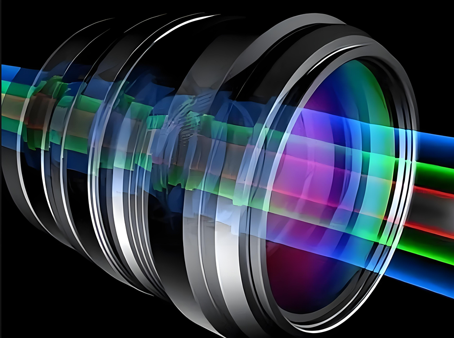
Concept and Packaging Prototypes
Early prototypes help teams evaluate the instrument envelope, component access, cable routing, user interaction, mounting interfaces and assembly sequence. A printed enclosure may answer packaging questions quickly, while a machined plate or bracket may provide more realistic stiffness and thread behavior. The prototype process should be selected according to the question being tested rather than by appearance alone.
At this stage, engineers should identify the mechanical interfaces that will later control optical alignment. Temporary datums, reference surfaces and adjustment ranges can be included in the prototype so that design decisions are based on measurable relationships instead of visual fit alone.
Functional and Alignment Builds
Functional prototypes reproduce the material, interfaces and dimensional relationships needed for meaningful testing. Machined barrels, mounts, sensor plates and housings can verify concentricity, seating, thread engagement, preload, heat transfer and adjustment access. Fabricated panels and frames can verify equipment integration, while molded or cast plastic parts can evaluate assembly, texture, color and handling.
The test plan should distinguish mechanical verification from optical verification. A measured bore, shoulder or mounting pattern can establish mechanical conformance, but it does not prove focus, image quality, transmission, reflectance or detector performance. The customer should define how mechanical measurements connect to the optical alignment and system acceptance plan.
Pilot Instruments and Engineering Units
Pilot quantities expose variation that a single prototype may not reveal. Workholding repeatability, coating buildup, thread fit, part cleanliness, assembly stack-up and inspection correlation become more important when several units are built. A controlled drawing should identify functional datums, critical characteristics, material grade, finish, cosmetic zones and requested records.
Where matched sets or serialized assemblies are required, identify the pairing, marking and traceability rules during quotation. Do not rely on informal workshop selection to correct an unspecified stack-up.
Approved Repeat Production
Repeat orders require stable inputs: drawing revision, approved deviations, material condition, finish specification, inspection method and packaging requirements. Tooling, fixtures and measurement programs should be maintained against the released configuration. Engineering changes should be communicated before the next lot rather than discovered during inspection or assembly.
Optical Equipment Manufacturing Capabilities
CNC Machining for Precision Optical Hardware
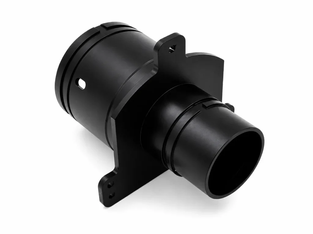
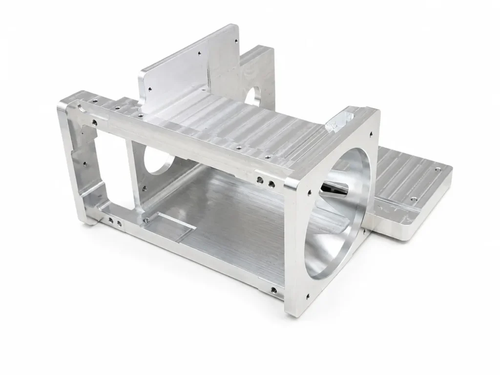
CNC machining services support mounts, barrels, camera housings, detector carriers, base plates, heat sinks, aperture hardware, alignment fixtures and instrument frames in metals and engineering plastics. CNC milling is suited to multi-sided housings, pockets, datum faces, mounting patterns and complex access features. CNC turning is efficient for cylindrical barrels, retaining rings, sleeves, spacers, adapters and concentric interfaces.
DFM review considers workholding, setup count, datum transfer, thin-wall stability, deep bores, internal radii, thread relief, burr control, finish allowance and inspection access. Tolerances are evaluated feature by feature. A capability can only be confirmed after reviewing material, geometry, feature size, part condition, production route and the specified measurement method.
Injection Molding for Optical-Instrument Plastic Parts
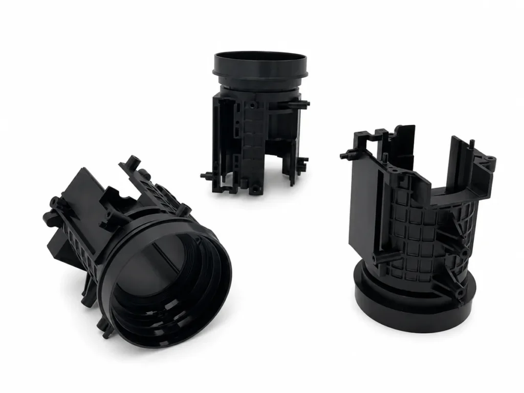
Plastic injection molding can support equipment covers, internal carriers, cable guides, bezels, sensor housings, knobs, protective caps and other repeat plastic components. Part design should account for wall uniformity, draft, ribs, bosses, gates, ejector locations, inserts, texture and cosmetic zones.
Transparent covers or light-guiding parts require special caution. Resin grade, moisture control, molded stress, gate location, surface condition, haze, transmission and visual acceptance must be defined for the application. A clear molded part is not automatically an optical lens, and mechanical dimensional inspection does not establish optical performance.
Sheet Metal Fabrication for Instruments and Enclosures
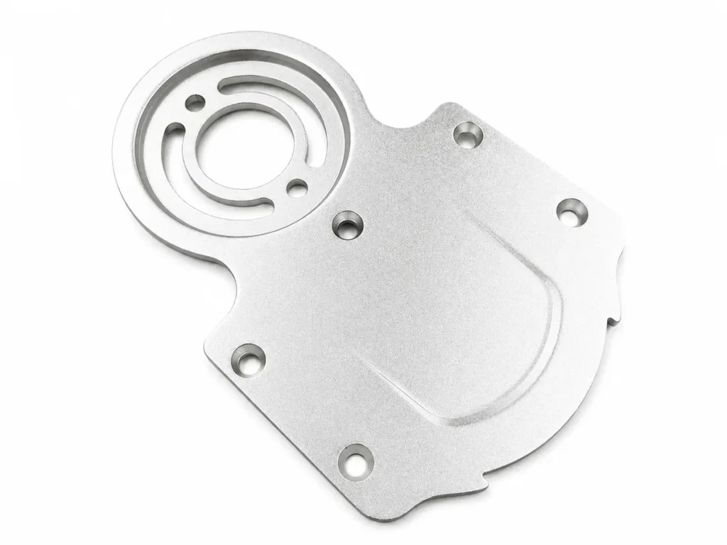
Sheet metal fabrication can produce instrument panels, chassis, brackets, covers, cable-management parts, light-control enclosures and welded frames. Laser cutting, punching, bending, hardware insertion, welding and finishing are combined according to the design.
Important inputs include alloy and thickness, bend radius, hole-to-bend distance, hardware access, weld symbols, cosmetic surfaces and final inspection condition. Large panels and welded structures may move during fabrication or finishing, so datum features and allowable flatness should reflect how the assembly is mounted. Light-tight or environmental performance must be defined by an acceptance test; it should not be inferred from a closed-looking enclosure.
3D Printing and Vacuum Casting for Development
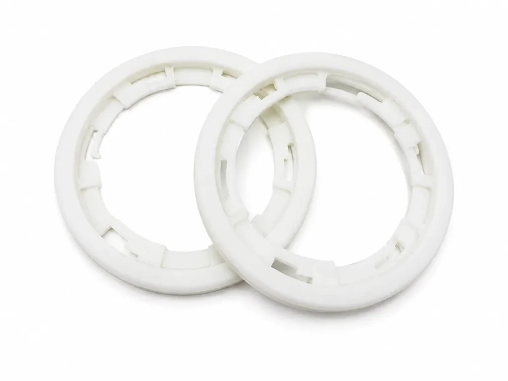
3D printing can accelerate complex baffles, ducts, alignment aids, protective covers, cable guides and assembly fixtures. Process choice matters because photopolymer, powder-bed polymer and metal parts have different accuracy, porosity, anisotropy, surface and environmental behavior.
Vacuum casting can reproduce a master pattern in polyurethane for appearance evaluation, assembly trials and small groups of similar housings or covers. Cast polyurethane may simulate the appearance and feel of molded plastic, but it is not automatically equivalent to a specified production thermoplastic or suitable for optical transmission tests.
Why Choose SAMSHION for Optical Equipment Parts?
Multiple Manufacturing Processes Through One Engineering Contact
An optical instrument can combine turned barrels, milled housings, fabricated panels, molded covers, printed fixtures and finishing. Coordinating these routes through one project team can reduce interface gaps while keeping every component tied to its own drawing and acceptance criteria.
DFM Focused on Functional Interfaces
Engineering review can identify inaccessible features, unstable walls, datum ambiguity, thread conflicts, coating allowance, molded-part risks and inspection limitations before manufacturing begins. Recommendations are returned for customer approval rather than applied as uncontrolled design changes.
Requirements-Based Inspection
Inspection is planned from the drawing and purchase requirements. Critical dimensions, requested records and acceptance methods should be agreed during quotation so the manufacturing and verification routes support the intended assembly.
Support from Prototype to Repeat Orders
The same manufacturing team can support design iterations, functional builds, pilot instruments and approved repeat components. Revision control, tooling condition and repeat-order requirements are reviewed as the program develops.
Representative Mechanical Components for Optical Systems
Lens Barrels, Retainers and Spacers
Barrels and retainers establish axial location, radial clearance and mechanical protection around optical elements. Drawings should define the functional axis, seating shoulders, thread form, reliefs, edge condition and finish requirements. If optical elements will be installed after finishing, coating thickness, particle control and assembly-tool access should be considered before release.
Fine threads and long bores can create measurement and cleaning challenges. Specify only the pitch, fit and runout required by the assembly, and provide a practical datum relationship between the thread, bore and seating face. A cosmetic black surface alone is not evidence of controlled internal reflectance.
Optical Mounts and Positioning Hardware
Mirror mounts, detector brackets, lens holders, stage adapters and adjustment plates depend on stiffness, access and repeatable contact. Kinematic contacts, flexures, dowel interfaces or clamp surfaces should be defined by function. Adjustment range and locking strategy should avoid transferring uncontrolled force into sensitive elements.
When a mount is used in a precision alignment chain, identify which surfaces establish position and which merely provide clamping. This distinction allows machining and inspection effort to focus on the characteristics that affect the optical axis.
Camera, Sensor and Detector Housings
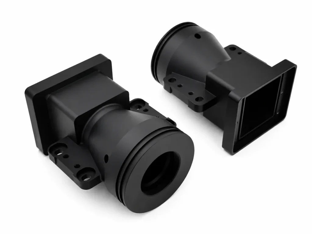
Imaging housings may combine a controlled mounting face, sensor seat, connector access, sealing features, thermal paths and light-control geometry. The design should identify the detector reference plane, interface datums, allowable assembly stack-up and any finish exclusions at grounding or heat-transfer surfaces.
If the housing dissipates heat, thermal performance depends on the complete assembly, contact resistance, airflow and duty cycle. SAMSHION can manufacture the defined housing and dimensional interfaces; the equipment designer remains responsible for thermal analysis and system validation.
Instrument Frames, Enclosures and Thermal Supports
Machined frames, fabricated chassis, cooling plates and heat sinks support optics, electronics and motion components. Their structural and thermal behavior depends on geometry, material, joint design and boundary conditions. Drawings should distinguish controlled mounting interfaces from general envelope surfaces and specify the condition in which large or flexible parts are inspected.
Alignment Fixtures and Test Adapters
Fixtures can support assembly, inspection, alignment setup and repeatable handling. A useful fixture provides stable datums, accessible clamping and a documented relationship to the controlled product feature. It should not be represented as a calibrated acceptance instrument unless it has been qualified for that purpose.
Materials for Optical Equipment Parts
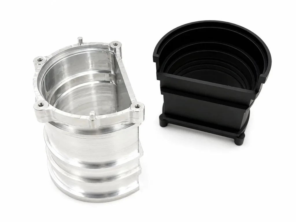
Material selection should consider stiffness, thermal expansion, mass, conductivity, corrosion, magnetic behavior, outgassing, machinability, finish compatibility and availability. The exact grade and condition should be specified because generic labels such as “aluminum,” “stainless” or “plastic” do not define performance.
Aluminum Alloys
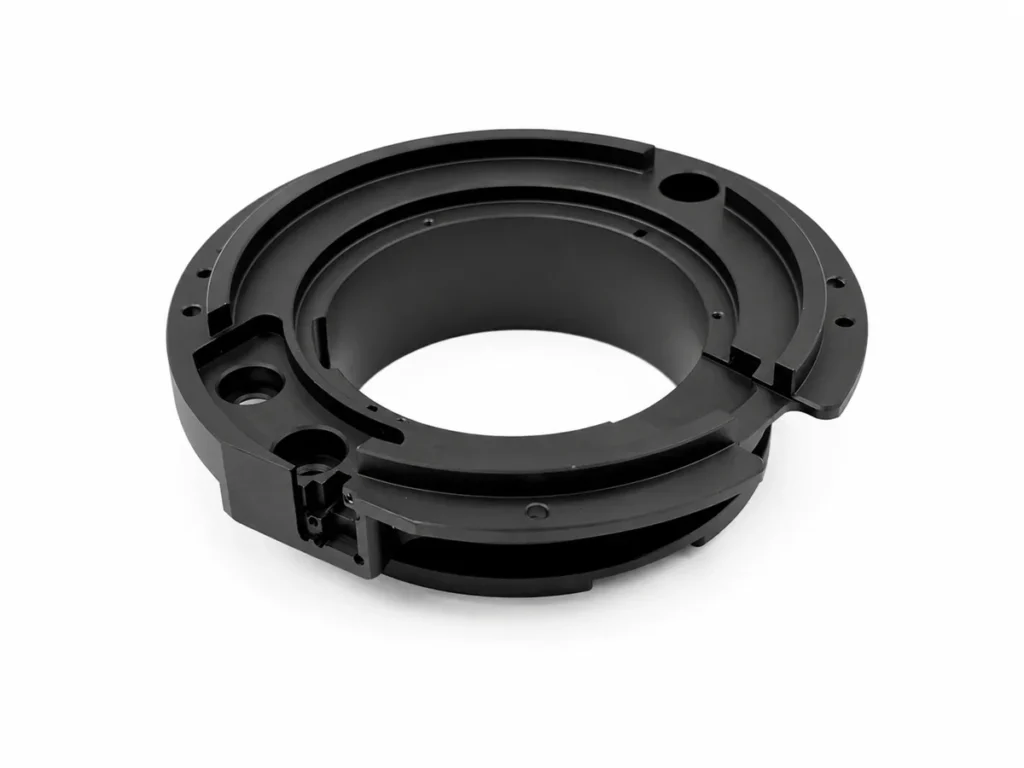
Aluminum is frequently selected for mounts, housings, frames, plates and heat sinks because it combines low mass, machinability and useful thermal conductivity. Alloy, temper and finish influence dimensional stability, strength, corrosion behavior and appearance. Thin sections, asymmetric pockets and heavy material removal may require a staged machining strategy.
Stainless Steel, Tool Steel and Specialty Metals
Stainless steel can provide stiffness, wear resistance and corrosion performance for inserts, mounting features and compact hardware. Tool steel may be appropriate for wear elements or fixtures. Brass, copper and titanium may be considered where conductivity, bearing behavior, mass or environmental requirements justify them. Grade, heat treatment, hardness and final finish must be coordinated with machining and inspection.
Engineering Plastics
POM, nylon, PC, ABS, PEEK, PTFE and other engineering plastics can support isolation, low friction, reduced mass, chemical resistance or molded geometry. Moisture absorption, thermal expansion, creep, reinforcement and machining or molding history can change dimensions. Our manufacturing materials guide provides process-oriented context, while the project drawing should identify the approved grade and functional requirements.
Transparent Polymers and Clear Components
PMMA and PC may be considered for covers, windows, indicators or light-management components, but their suitability depends on optical, environmental and mechanical requirements. Surface quality, haze, transmission, birefringence, scratch resistance, UV exposure and coating compatibility require application-specific evaluation. SAMSHION should not be assumed to certify lens quality or optical-grade performance unless the exact test and acceptance criteria have been contracted.
Surface Finishes, Blackening and Cosmetic Control
Finishes may provide corrosion protection, wear resistance, electrical behavior, thermal behavior, appearance or reduced visible reflections. Depending on substrate and project requirements, options may include anodizing, hard anodizing, passivation, electroless nickel plating, bead blasting, polishing, painting, powder coating and laser marking.
Black anodizing, paint or other dark finishes can support stray-light control, but color alone does not define spectral reflectance or performance across a wavelength range. If reflectance matters, the customer should specify the relevant wavelength, angle, surface preparation and acceptance method. Internal baffles, grooves and geometry may be as important as coating selection.
The finish specification should identify substrate, finish type or governing standard, thickness where relevant, gloss or texture reference, masked areas, optical interfaces, threads, electrical contacts, sealing faces and cosmetic zones. Coating buildup can change fits and thread engagement. SAMSHION coordinates project-appropriate options through its surface finishing services and confirms the acceptance scope before production.
Design Guidelines for Optical Equipment Components
Define the Mechanical Relationship to the Optical Axis
Start by identifying the axis, plane or coordinate system used by the optical design. Translate that intent into manufacturable datums such as a mounting face, pilot diameter, precision bore, dowel pattern or shoulder. Avoid a drawing in which critical features are dimensioned from cosmetic edges or unrelated surfaces.
Control Concentricity, Runout and Axial Location by Function
A barrel assembly may depend on bore size, circular runout, shoulder squareness and axial spacing. Assign each requirement to a functional datum and final part condition. Do not apply a single tight geometric tolerance to every cylindrical surface when only one or two interfaces control alignment.
Manage Stack-Up Across Mounts and Housings
Focus, detector position and optical alignment are assembly results. Review the stack across barrels, spacers, retainers, mounts, sensor seats and fasteners. Tolerancing one part without examining mating components can create a drawing that is expensive to manufacture but still does not control the system result.
Design Threads and Retainers for Assembly
Provide thread relief, tool access and sufficient engagement. Define locking, preload and anti-rotation methods where needed. Avoid sharp tool-exit conditions near seating surfaces. If the thread and bore share an alignment function, establish a measurable datum strategy and discuss how the relationship will be verified.
Account for Thermal Expansion and Heat Flow
Optical instruments may experience focus shift, detector movement or alignment change with temperature. Material expansion, heat sources, mounting constraints and contact interfaces must be considered at the system level. Mechanical parts can be manufactured to defined dimensions, but thermal stability must be validated in the assembled operating condition.
Reduce Burrs, Particles and Damage Risk
Small burrs near apertures, threads and seating faces can interfere with assembly or generate particles. Identify critical clean areas and edge requirements. Design blind holes, intersecting passages and internal grooves so they can be deburred, cleaned and inspected. Packaging should protect finished surfaces and prevent part-to-part contact where appearance or cleanliness matters.
Plan Finish Allowance and Masking
Anodizing, plating, paint and blasting affect size and surface condition. Drawings should state whether dimensions apply before or after finish and identify masked datums, bearing fits, grounding points, sealing faces and optical interfaces. Thread and bore allowances should reflect the selected finishing route.
Preserve Adjustment Access and Structural Stiffness
Adjustment screws, locks, cable connectors and mounting fasteners must remain accessible in the assembled instrument. Thin walls, long overhangs and interrupted sections can deflect during machining, assembly or use. Provide local stiffness and clampable features where possible, and avoid using tight tolerances as a substitute for structural design.
Specify Cleanliness and Cosmetic Acceptance Clearly
Terms such as “clean,” “scratch-free,” “light-tight” or “optical black” are incomplete without an acceptance reference. Define protected surfaces, allowable marks, particle or residue limits, cleaning restrictions, inspection lighting and packaging expectations. If a formal cleanliness standard applies, include the exact scope and verification method.
Quality Control and Alignment Evidence
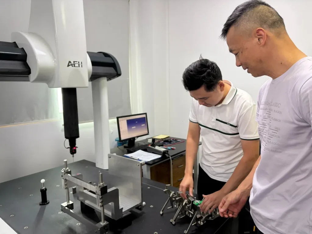
SAMSHION operates an ISO 9001:2015-certified quality management system. Quality planning begins with the controlled drawing and confirmed purchase requirements. Depending on project scope, agreed activities may include material review, first-piece checks, in-process inspection, final dimensional inspection, visual inspection, functional gauges, measurement reports and supplier finish certificates.
Mechanical features may be inspected with suitable dimensional equipment such as CMMs, height gauges, bore gauges, micrometers, optical comparators or project-specific fixtures. The word “optical” in optical comparator describes the measurement instrument; it does not mean that SAMSHION has verified lens performance, image quality or photonic function.
The customer should identify critical characteristics, datums, sampling requirements, report format and any special part condition. Flexible, coated or assembled parts may require an agreed fixture, restraint and temperature condition. If alignment evidence requires a special artifact, master, autocollimator, interferometer or optical bench, the exact method and responsible party must be confirmed before quotation.
Material certificates, calibration records and dimensional reports provide evidence for their stated scope. They do not by themselves establish optical performance, laser safety, cleanroom compatibility, thermal stability, environmental rating or regulatory approval.
Optical Equipment Manufacturing FAQ
Does SAMSHION manufacture optical lenses?
This page focuses on mechanical and plastic components used around optical systems, such as barrels, mounts, housings, frames and fixtures. Lens design, polishing, optical coating and optical-performance qualification are not claimed unless a specific sourced activity is reviewed and documented.
What files should I send for a quote?
Send a 3D CAD model and a controlled 2D drawing when tolerances, datums, material, finish, threads, cosmetic zones or inspection records matter. Include quantity, revision and any interface connected to the optical axis or detector plane.
Can you machine lens barrels and retaining rings?
Yes, subject to design review. The drawing should define the functional axis, bore and shoulder relationships, thread requirements, edge condition, material, finish and the final condition used for inspection.
Can SAMSHION support black optical hardware?
Black anodizing, painting and other dark finishes may be available according to substrate and project scope. If spectral reflectance or stray-light performance matters, the wavelength, surface preparation and test method must be specified because color alone is not a performance specification.
Can you make clear plastic optical parts?
SAMSHION can review clear covers, windows and molded plastic components. Resin, geometry, surface, haze, transmission, stress and environmental requirements must be defined. A clear molded part is not automatically an optical-quality lens.
What tolerances can you hold on optical mounts?
Tolerance capability depends on material, geometry, feature size, wall stiffness, setup strategy, finish and measurement method. Send the drawing so the critical characteristics can be reviewed individually instead of relying on a universal tolerance claim.
Can inspection reports be supplied?
Requested dimensional reports, material records or finish certificates can be reviewed during quotation. Identify the characteristics, sampling, format and documentation expectations before production so the inspection plan can be aligned.
Do you provide cleanroom manufacturing or optical calibration?
Do not assume cleanroom classification, precision cleaning, optical calibration or system-level performance testing from this page. If the project requires a special environment, cleaning process or optical test, provide the exact standard and acceptance method for review.
Which manufacturing process is best for an optical equipment prototype?
The right process depends on the validation objective. CNC machining may be preferred for datum relationships and threads; 3D printing for complex packaging and fast iteration; sheet metal for chassis and panels; and molding or vacuum casting when production-like plastic behavior or appearance must be evaluated.
Can you support repeat production after prototyping?
Yes. After the design and acceptance requirements are approved, SAMSHION can review a low-volume or repeat production route. Revision control, tooling, finish, inspection and packaging requirements should be maintained for each released order.