
5-Axis CNC Machining Services for Complex Custom Parts
Machine multi-sided features, angled holes, deep cavities and complex contoured surfaces with a process matched to the geometry. SAMSHION supports indexed 3+2 and simultaneous 5-axis machining for one-off prototypes, low-volume batches and repeat production in metals and engineering plastics.
- No MOQ, starting from one part
- DFM and inspection planning before machining
- Selected critical features to ±0.005 mm after engineering review
- All uploads are secure and confidential.
5-Axis CNC Machining Capabilities
SAMSHION operates multiple 5-axis machining centers across different travel classes. We select the machine and machining strategy according to part geometry, tool access, workholding, tolerance relationships, quantity and inspection requirements.
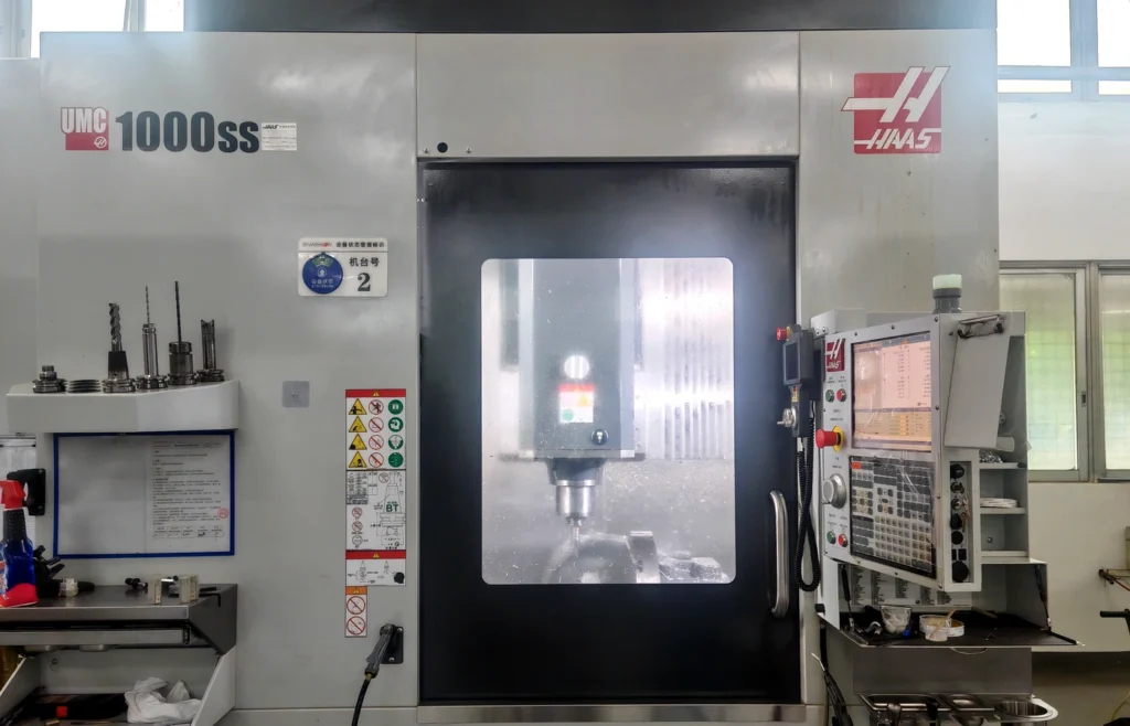
Largest-Travel Platform: Haas UMC-1000SS
SAMSHION uses the Haas UMC-1000SS for larger multi-sided parts and components that require extended linear travel, rotary positioning or continuously changing tool orientation. The platform supports both indexed 3+2 and simultaneous 5-axis machining.
Machine-axis travel and platter diameter do not define a guaranteed finished-part size. The usable machining envelope depends on the workpiece geometry, fixture height, tool and holder length, required rotary angles and collision clearance. Submit the current CAD model so the complete setup can be reviewed before quotation.
Why Choose Samshion for 5-Axis CNC Machining
SAMSHION combines engineering review, 5-axis programming, controlled production and drawing-based inspection. Each project is planned around the actual part geometry and approved requirements rather than treated as a standard machine-only job.
Engineering Review Before Programming
The CAD model and controlled drawing are reviewed for datums, tool access, wall stability, tolerance relationships, finishing and inspection. Questions affecting function, process route, cost or schedule are clarified before programming begins.
5-Axis Programming and Collision Verification
For indexed 3+2 and simultaneous 5-axis machining, CAM toolpaths are checked against machine travel, rotary limits, the complete tool and holder, workholding, remaining stock and collision clearance before the setup is released to production.
Controlled Prototype-to-Production Transfer
Approved programs, setup information, workholding, drawing revisions and inspection checkpoints are controlled for later quantities. Changes to the design, material, finish or acceptance requirements are reviewed before repeat production.
Drawing-Based Inspection
Internal first-off and process-stability checks are completed before production continues. CMM, on-machine probing, bore gauges, pin gauges and thread gauges are selected according to the feature, tolerance and agreed inspection scope.
Real 5-Axis CNC Machining Projects
The examples below are based on actual parts. Each case shows how its geometry, tool access and drawing-defined requirements influenced the machining strategy and inspection plan.
Simultaneous 5-Axis Machining for a One-Piece Optical Component
Accessible features were produced by 3-axis machining, while simultaneous 5-axis machining was used for the multi-angle geometry and deep slots. A fixed-angle 3+2 strategy did not provide sufficient usable work envelope and tool-holder clearance for all features.
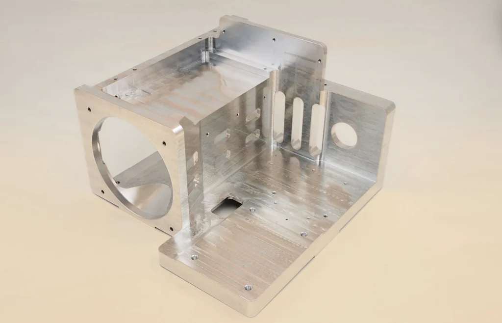
Flatness, parallelism and perpendicularity were each controlled to 0.03 mm. H7 locating bores were machined together with controlled bore-to-datum location and orientation relationships to support the intended coaxial lens assembly. CMM inspection was used for datum-related geometry, with thread gauges and pin gauges used for applicable threaded and hole features.
The combined 3-axis and simultaneous 5-axis process provided access to the multi-angle and deep-slot features while maintaining the specified geometric and locating-feature requirements across the small batch.
Simultaneous 5-Axis Machining for Datum-Related Multi-Directional Features
Accessible geometry was produced by 3-axis machining, while simultaneous 5-axis machining was used for features that required continuously changing tool orientation. A fixed-angle machining strategy did not provide sufficient access for all of the multi-directional features and selected intersecting hole or passage geometry.
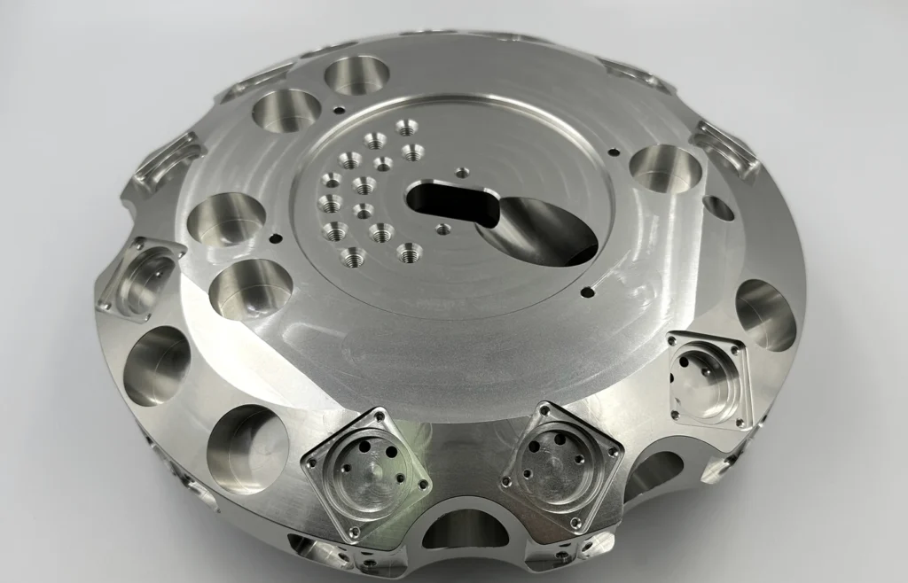
The part included strict positional and bore-diameter tolerances, with features approached from different directions but related to common datum surfaces. CMM inspection was used for datum-related position and geometric relationships, while bore gauges, pin gauges and thread gauges were used for the applicable bore, hole and threaded features.
The combined machining route provided access to the linked multi-directional and intersecting features while preserving a common datum strategy and supporting verification of the controlled hole and positional characteristics with the specified inspection methods.
Simultaneous 5-Axis Machining for a Deep-Cavity Lighting Component
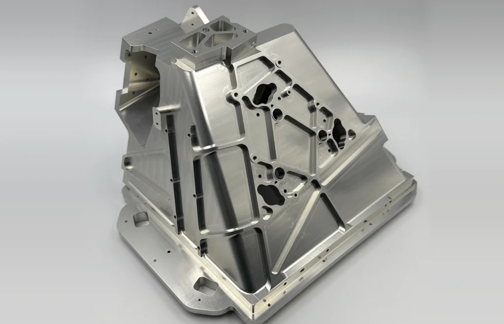
This one-piece prototype was machined from solid 6061-T6 aluminum using a combination of 3-axis and simultaneous 5-axis machining. Simultaneous tool motion was used in the deep cavity to manage tool-holder clearance, reach smaller internal corner radii without relying on EDM corner cleanup, follow continuous surfaces and access holes from multiple directions.
Drawing and Inspection Focus
The H7 locating holes and the relationships between features machined from different directions required a coordinated datum and inspection strategy. Process planning also considered long-tool rigidity, chatter risk and thin-wall deformation in the deep-cavity areas. CMM inspection was used for datum-related geometry and multi-face feature relationships, with thread gauges and pin gauges used for the applicable threaded and hole features.
Project Outcome
The combined machining route enabled the one-piece prototype to be produced from solid material with access to the deep cavity, continuous surfaces and multi-directional holes, without relying on EDM for internal-corner cleanup. The inspection plan provided a practical method for verifying the H7 locating holes and the relationships between features on different faces.
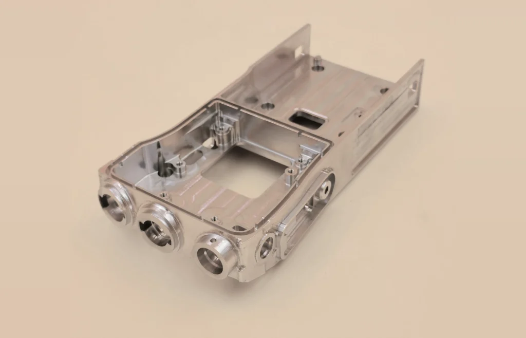
Combined 3-Axis and 5-Axis Machining for a Wireless Device Component
This low-volume wireless-device component was machined from solid 6061-T6 aluminum using a combined 3-axis and 5-axis route. Five-axis machining was applied to manage tool-holder clearance, follow continuous surfaces and reduce datum transfers between features on different faces. The process plan also accounted for thin-wall deformation and long-tool rigidity.
Drawing and Inspection Focus
The drawing specified H7 hole tolerances together with positional requirements for features located on multiple faces. These characteristics were treated as separate size and location controls within a coordinated datum and inspection strategy. CMM inspection was used for datum-related position and multi-face relationships, while pin gauges and thread gauges were used for the applicable hole and threaded features.
Project Outcome
The combined machining route provided access for the continuous surfaces and multi-face features while reducing datum transfers for the relevant geometry. The inspection plan provided a practical method for verifying the H7 hole sizes, positional requirements and applicable threaded features across the low-volume batch.
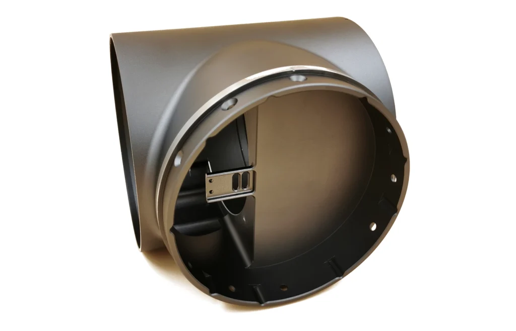
Combined 3-Axis and 5-Axis Machining for a Thin-Wall Robotics Component
This low-volume robotics component was machined as one complete part from solid 6061-T6 aluminum using a combined 3-axis and 5-axis route. Five-axis machining provided access to features oriented along multiple surface normals, while the process plan accounted for the large curved surfaces, deep internal cavity, thin-wall deformation, long-tool rigidity and positional relationships between features on different faces.
Drawing and Inspection Focus
The H7 size requirement for the large bore was controlled separately from its coaxiality and positional relationships to the applicable datums. Profile requirements and wall thickness also had to be considered across the large curved and thin-wall areas. The inspection plan combined CMM inspection with thread gauges, pin gauges and a coating thickness gauge for the applicable geometric, hole, threaded and anodized-surface
Project Outcome
The combined machining route provided access to the deep cavity, large curved surfaces and features oriented along multiple surface normals while supporting a coordinated datum strategy for the multi-face geometry. The inspection plan provided practical coverage for the H7 bore, coaxiality, position, profile, wall thickness, applicable threaded and hole features, and anodized coating thickness.
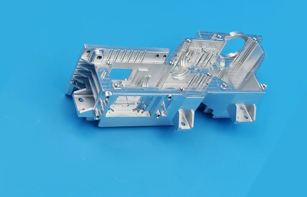
Combined 3-Axis and Simultaneous 5-Axis Machining for an Optical and Infrared Component
This prototype optical and infrared component was machined as one complete part from solid 6061-T6 aluminum using a combined 3-axis and simultaneous 5-axis route. Simultaneous tool orientation provided access to features across multiple faces and within deep cavities while maintaining clearance between the tool holder and the part. The process plan also addressed thin-wall deformation, long-tool rigidity, chatter risk and positional relationships between features on different faces, while limiting unnecessary datum transfers.
Drawing and Inspection Focus
The H7 size requirements were treated separately from the positional and orientation relationships of the applicable features. CMM inspection was planned for the specified position, perpendicularity, flatness and profile characteristics, while pin gauges and thread gauges provided functional checks for the applicable hole and threaded features.
Project Outcome
The combined machining route provided practical access to the deep cavities and features distributed across multiple faces while maintaining the tool orientations required for holder clearance. It also supported a coordinated datum strategy for the multi-face geometry and an inspection plan covering the specified H7, positional, perpendicularity, flatness, profile, hole and threaded characteristics.
How We Select a 5-Axis Machining Strategy
We select the machining route at both part and feature level within a common datum, workholding and inspection plan. A single component may combine 3-axis, indexed 3+2 and simultaneous 5-axis operations.
Indexed 3+2 for Fixed-Angle Features
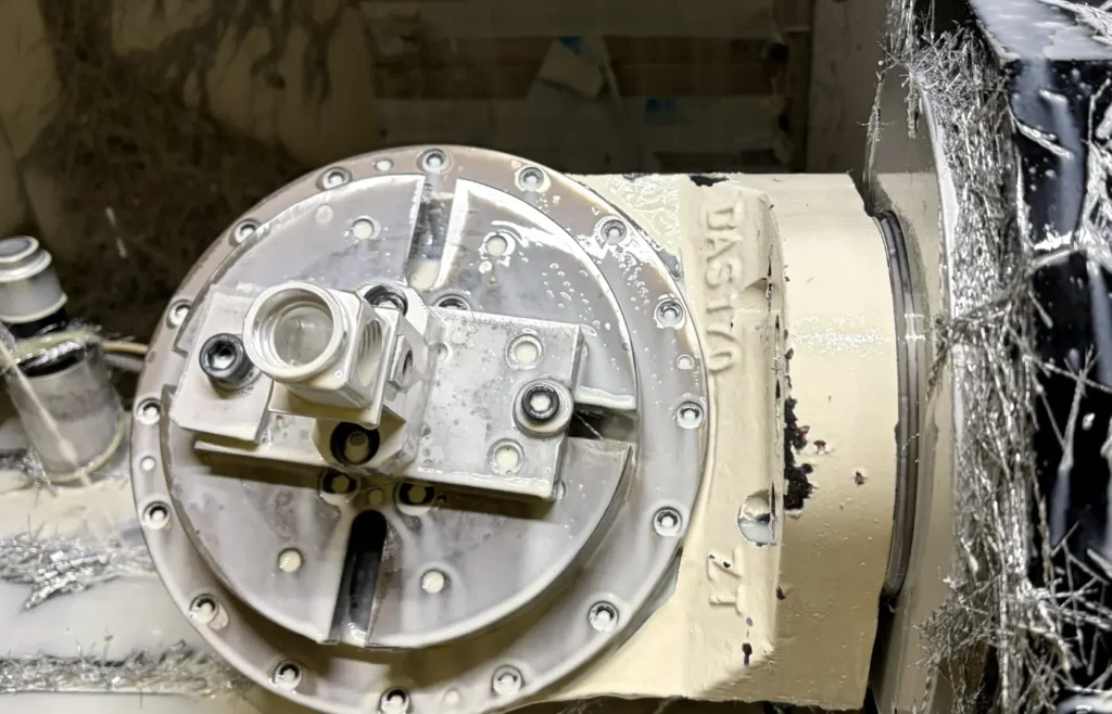
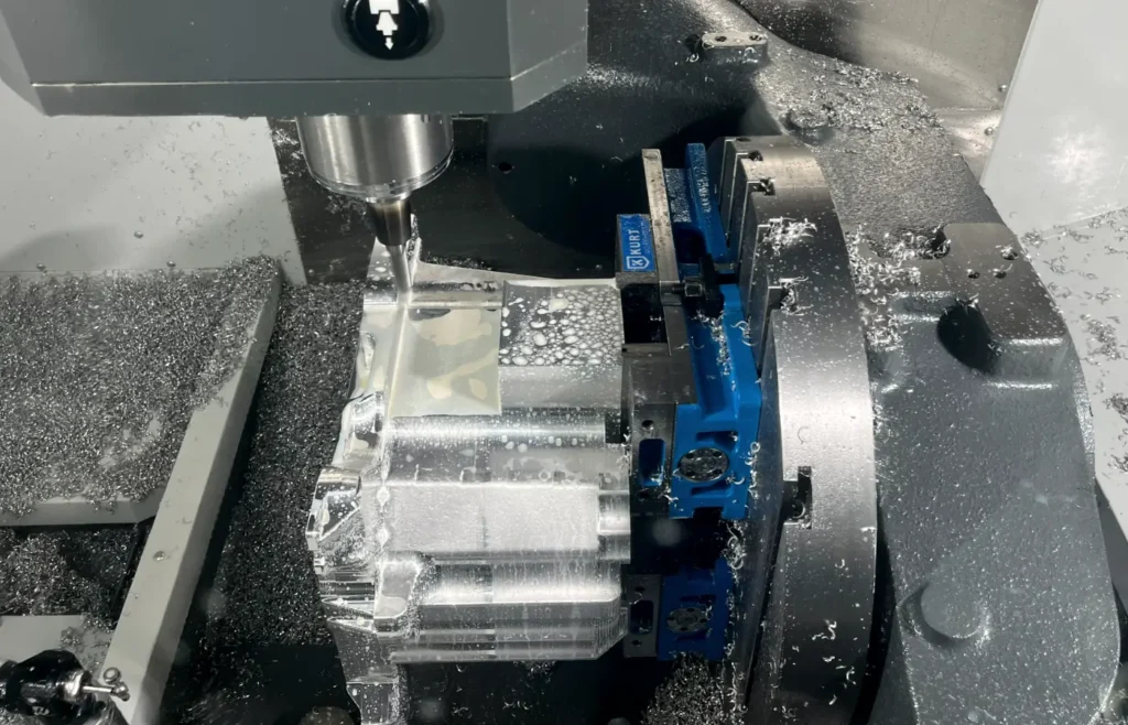
In indexed 3+2 machining, the rotary axes orient the workpiece and/or tool, then remain at fixed commanded angles while the linear axes perform the cut. This route may suit planar faces, angled holes, pockets and multi-sided features that can be reached safely from practical fixed orientations.
Simultaneous 5-Axis for Coordinated Tool Motion
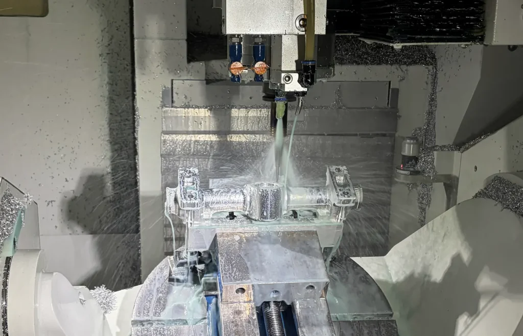
In simultaneous 5-axis machining, linear and rotary axes are interpolated together as required along the toolpath. This route may be preferred where continuous tool-axis reorientation provides a clear advantage in access, tool-holder clearance, surface control or process stability.
The final route is confirmed after reviewing the CAD model, controlled drawing, machine kinematics, workholding, tool and holder clearance, tolerances and inspection requirements.
Read our detailed guide to 3+2 vs. simultaneous 5-axis machining →
How We Verify a 5-Axis Setup
Before a CAM program is released for machining, the selected machine, fixture, stock, cutter and holder are reviewed as one complete setup. Tool access, rotary travel, clearance and setup references are checked for the planned operation to reduce avoidable collision and alignment risks.
Workholding Stability and Machining Access
The workholding method is selected according to part geometry, machining stage, cutting forces and the surfaces that must remain accessible.
Standard or custom workholding may be used to support the part while preserving access for multi-directional machining. Fixture height, clamping position and rotary clearance are reviewed together rather than treated as separate decisions.
Tool and Holder Clearance
Tool access depends on more than cutter diameter and reach. We also evaluate holder diameter, tool projection, cavity depth, wall geometry and the changing orientation between the spindle and workpiece.
Where a fixed tool direction does not provide sufficient access, simultaneous 5-axis motion may be used to maintain a suitable tool orientation and avoid interference around complex geometry.
Rotary Motion and Collision Verification
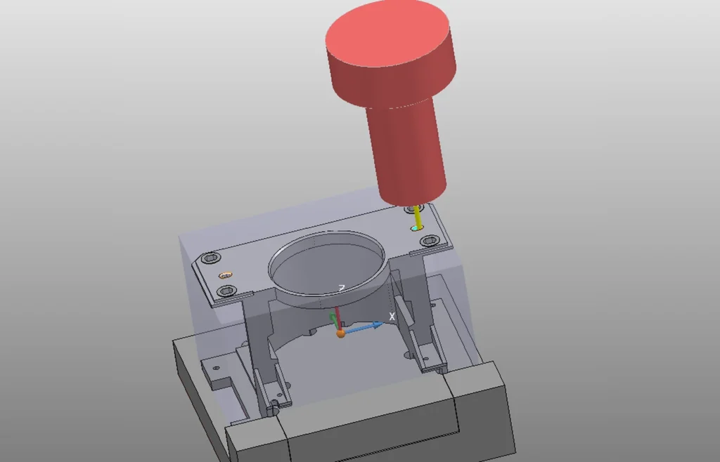
CAM verification is performed in the context of the planned machining setup. The tool, holder, stock, finished part, fixture, rotary trunnion and machine movement are reviewed through the programmed toolpath.
This allows potential clearance problems, rotary travel limitations and unsafe approach directions to be identified before the program is released to the machine.
Datum Planning and On-Machine Probing
Datum relationships are planned across the complete machining sequence, especially when features are located on different faces or the part moves between 3-axis and 5-axis operations.
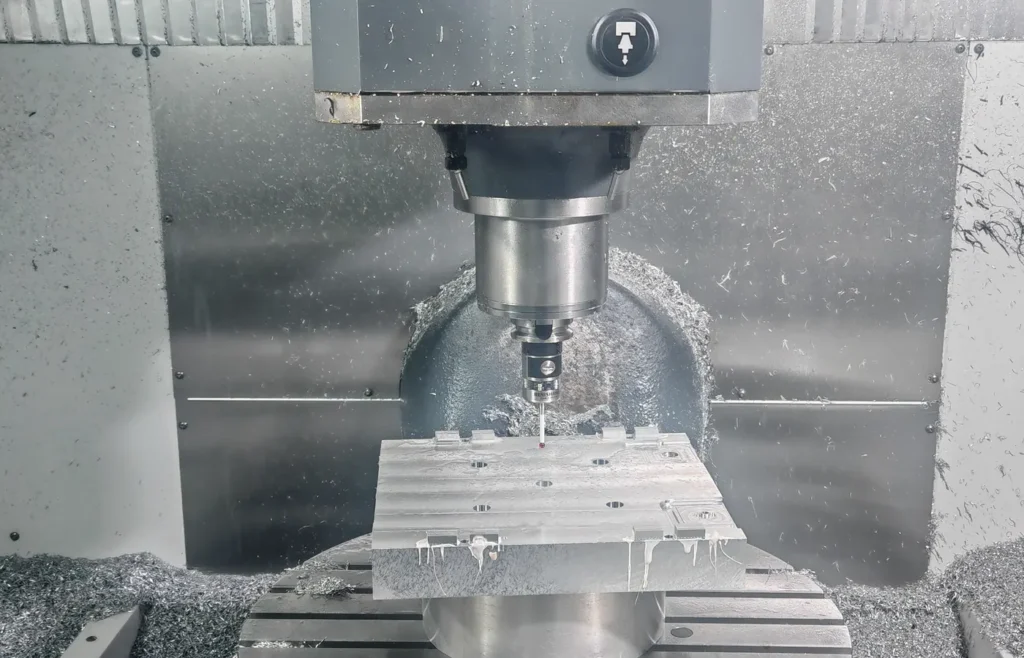
On-machine probing may be used for workpiece alignment, work-coordinate setup, datum verification after reclamping and selected in-process checks. Critical multi-face features are then inspected according to the controlled drawing and project requirements.
Machine-Context CAM Review
Toolpaths are reviewed with the selected cutter, holder, fixture, workpiece and rotary-axis limits to identify potential interference before the program is released.
On-Machine Probing
Where required by the setup plan, probing supports workpiece alignment, coordinate establishment and checks of selected setup references before or during machining.
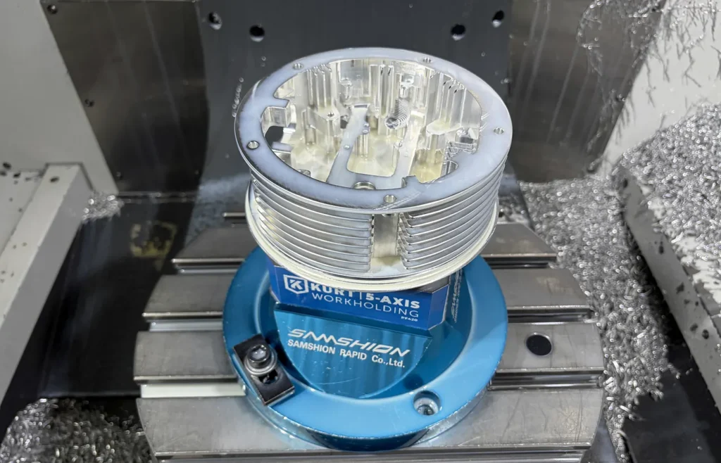
Project-Specific Workholding
Workholding is planned around cutting forces, part stability, feature access, rotary clearance and machining sequence. Standard or custom fixtures may be used according to the project requirements.
Materials for 5-Axis CNC Machined Parts
The materials below are representative options for 5-axis projects rather than a universal stock list. Feasibility is confirmed from the exact grade and condition together with part geometry, tool access, workholding, distortion risk, surface finish and inspection requirements.
Common Grades
6061-T6, 7075-T6 and other common aluminum grades. The exact alloy, temper, stock form and certification requirements are confirmed during quotation.
5-Axis Project Considerations
Thin walls, uneven stock removal, residual stress, workholding access and anodizing allowance can affect dimensional stability and the final machining plan.
Common Grades
303, 304, 316, 17-4 PH and other common stainless-steel grades. The specified material condition, hardness and any passivation requirements should be included in the RFQ.
5-Axis Project Considerations
Work hardening, heat generation, burr control, tool reach, wall stiffness and finishing requirements influence cutting strategy and tool selection.
Common Grades
Mild steel, 4140 and common tool-steel grades are available subject to project review. The exact grade, hardness and heat-treatment condition must be specified.
5-Axis Project Considerations
Material hardness, heat-treatment sequence, stock allowance, tool access, corrosion protection and final surface requirements can affect machining and inspection.
Common Grades
Common titanium grades, including Grade 2 and Grade 5 Ti-6Al-4V, are reviewed according to the specified condition, stock form and certification requirements.
5-Axis Project Considerations
Low thermal conductivity, cutting forces, heat concentration, tool engagement and tool reach require controlled machining parameters and a stable setup.
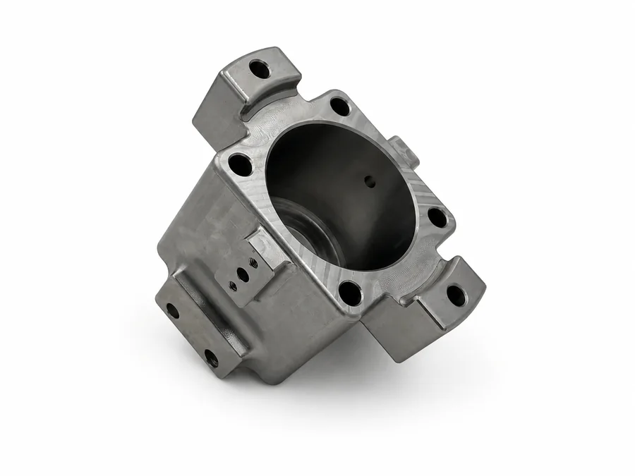
Common Grades
Common copper and machinable brass grades are available by quotation. The exact alloy, material condition, stock form and conductivity requirements should be identified.
5-Axis Project Considerations
Ductility, burr formation, surface marking, clamping pressure and alloy composition can affect tool selection, workholding and achievable surface condition.
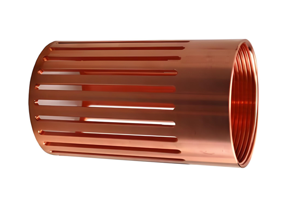
Common Grades
PMMA, POM, ABS, PC, nylon, PEEK and other machinable engineering plastics are available by quotation. The exact resin grade, filled or unfilled condition, color, transparency requirement and stock form should be specified.
5-Axis Project Considerations
Moisture absorption, thermal expansion, internal stress, clamping pressure and post-machining conditioning can affect dimensional stability and inspection results.
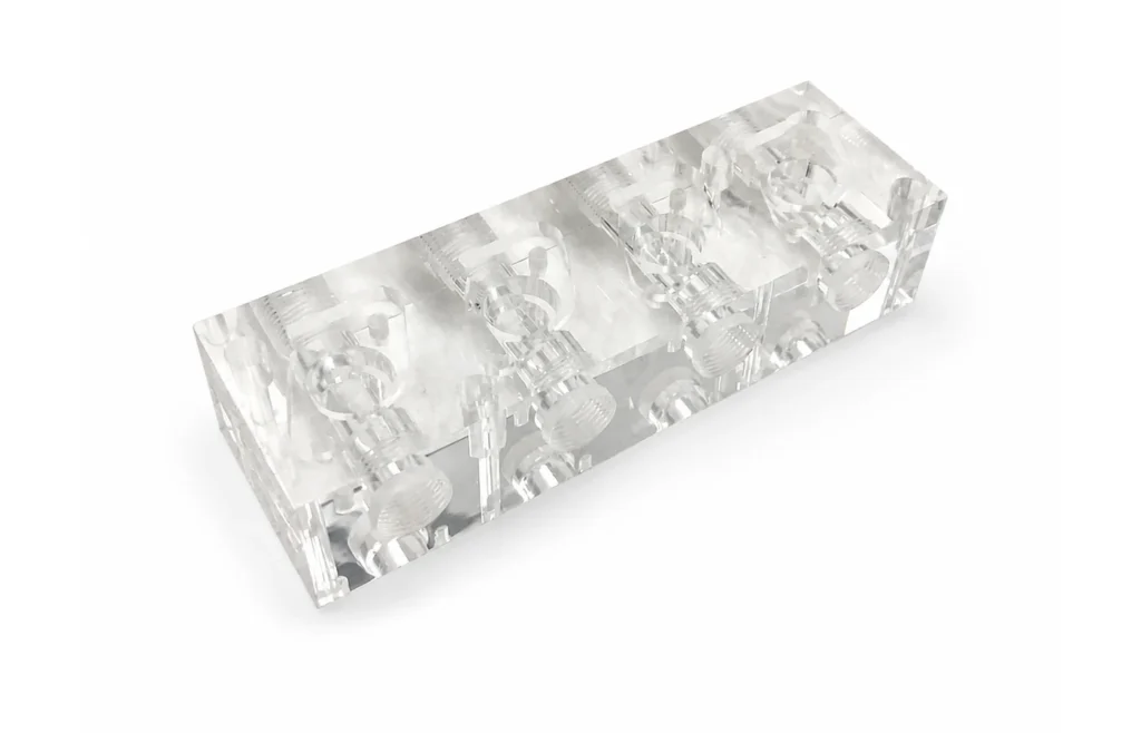
Include the exact grade, temper or condition, stock form and required documentation in the RFQ. Material certificates, Certificates of Conformance and lot or heat traceability can be provided when specified in the RFQ and agreed in the quotation. No material substitution is made without written approval.
Compare material families, properties and process suitability in our Manufacturing Materials Guide.
Surface Finishes for 5-Axis Machined Parts
Finishing must be planned with the machining and inspection route for multi-sided or contoured parts. Material removal or coating buildup can affect edge definition, surface texture, precision bores, threads, sealing faces and dimensions controlled in the finished condition. Complex geometry may also limit masking, polishing and inspection access.
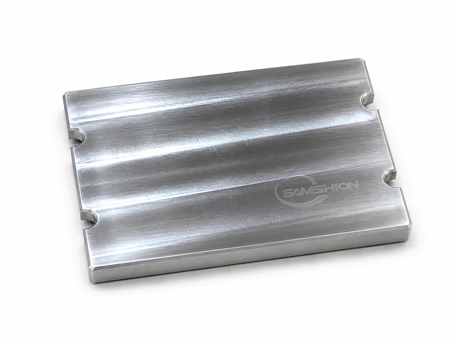
As-Machined
Visible tool marks remain unless a finer finish is specified. Our typical general finish is Ra 3.2 μm, while selected accessible surfaces may reach Ra 0.4 μm after engineering review. Define required roughness, edge breaks, burr limits and protected surfaces in the drawing.
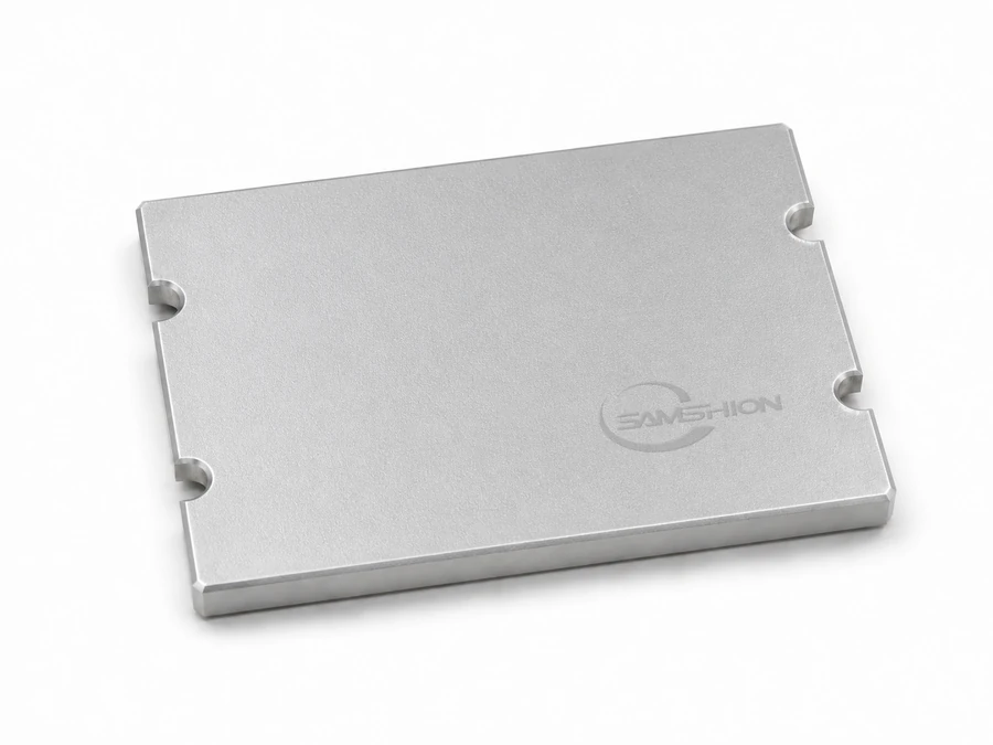
Bead Blasting
Bead blasting creates a more uniform matte texture and reduces visible variation in machining marks. Specify the target texture or approved sample, masking and dimensional sensitivity. Critical bores, threads, sealing faces and electrical contact areas can be protected when identified before production.
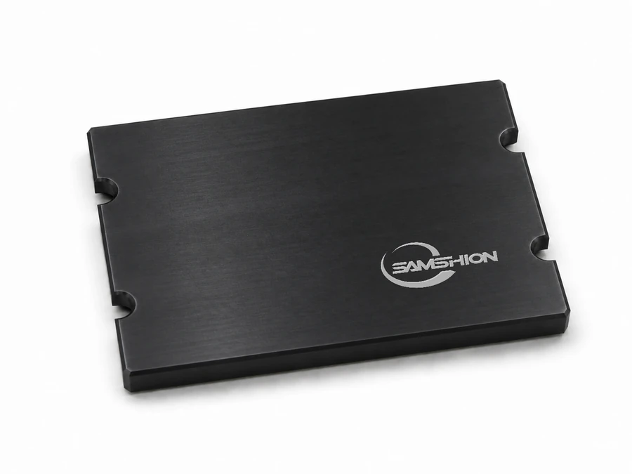
Anodizing
Anodizing is commonly used on aluminum parts for corrosion resistance, wear resistance or controlled appearance. Specify the required type, color, coating thickness, sealing and masking. Identify electrical contact areas, precision fits and any dimensions that must be verified after finishing.
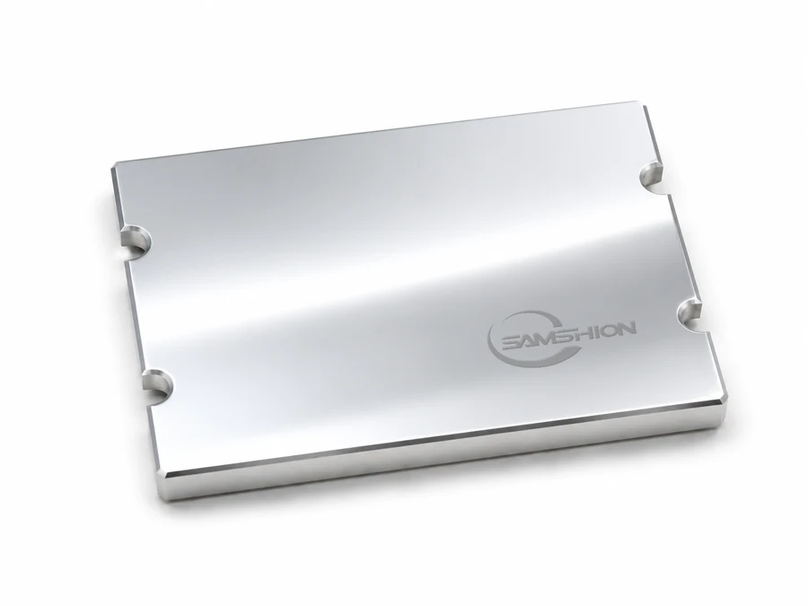
Polishing and Brushing
Polishing can reduce surface roughness on accessible features, while brushing creates a controlled directional texture. Specify the target roughness or approved appearance sample, required direction, protected areas and geometry to preserve. Acceptable edge rounding should also be defined before production.
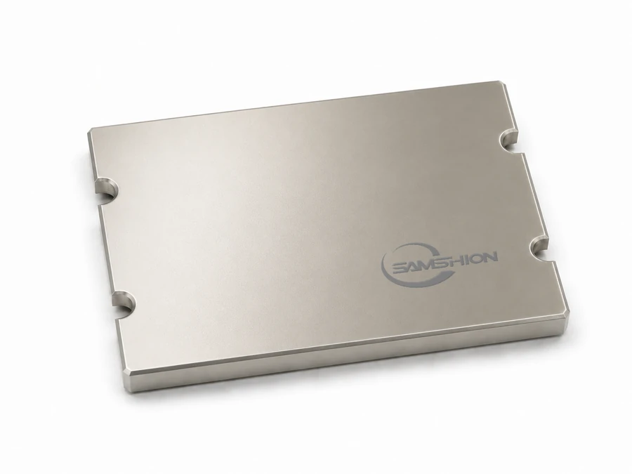
Electroless Nickel Plating
Electroless nickel plating applies a uniform metallic coating to suitable parts requiring wear or corrosion resistance. Specify the base material, coating thickness, masking and testing requirements. Critical fits, threads and dimensions that apply after plating should be identified before production.
Powder Coating
Powder coating provides a durable colored finish for suitable metal parts. Specify the required color, gloss, texture, coating thickness and cosmetic zones. Threads, precision fits, grounding points and other surfaces that must remain uncoated should be clearly identified before production.
Review the broader surface finishing options and identify the controlled finish specification in the drawing or purchase order. Avoid terms such as “smooth,” “perfect” or “mirror finish” without an objective roughness, sample or appearance standard.
From Quote to Finished 5-Axis Parts
Each project follows a controlled path from file review and route approval to machining, finishing, inspection and shipment.
Submit Your Project Files
Upload the latest 3D CAD model and controlled 2D drawing where required, together with the material, quantity, finish, target delivery date and inspection or documentation requirements.
Engineering and DFM Review
We review geometry, datum relationships, tool and holder access, workholding, rotary clearance, tolerances and inspection requirements. Questions, assumptions and proposed DFM changes are returned for confirmation before the route is finalized.
Confirm the Quotation
The quotation records the approved files and revision, material, quantity, machining route, finish, inspection scope, documentation, lead time and commercial terms. Production is released only after the requirements and quotation are approved.
Programming and Machining
The approved revision is programmed and verified for the selected 3-axis, indexed 3+2, simultaneous 5-axis or combined route. An internal first-off or first-stable-setup check is completed before the remaining quantity proceeds, with planned checks performed during machining.
Finishing and Inspection
Parts receive the specified deburring, edge treatment and surface finish. Drawing-defined dimensions, GD&T and cosmetic requirements are checked in the finished condition according to the agreed inspection scope.
Packaging and Delivery
Finished parts are cleaned, protected and packaged according to their geometry and surface condition. Reports and certificates are included as agreed in the quotation, and the order is released using the confirmed shipping method.
Design Guidelines for Reliable 5-Axis CNC Machining
Reliable 5-axis machining begins with geometry and requirements that can be manufactured, measured and inspected. These guidelines can reduce unnecessary tool reach, setup risk and clarification before quotation.
Define Functional Datums and Critical Features
Identify the surfaces, bores and axes that control assembly, sealing, alignment or motion on the 2D drawing. The machining and inspection plans should reference the same datum structure. Five-axis access can reduce setup transfers, but it cannot resolve ambiguous functional relationships.
Allow Tool and Holder Access
The cutting edge, tool shank and holder all need a collision-free path. Deep pockets, undercuts, close walls and hidden intersections should be reviewed with the complete tool assembly. Additional clearance can permit a shorter, more rigid tool and a more stable process.
Use Practical Internal Radii and Cavity Proportions
Milling cutters cannot create perfectly sharp internal corners. Larger non-functional radii and reasonable cavity proportions can reduce long-tool use, vibration and finishing time. Identify corners that are functionally critical instead of applying the smallest possible radius throughout the design.
Protect Thin Walls and Slender Features
Thin walls and tall features can move under cutting and clamping forces. Where possible, increase local stiffness, avoid abrupt thickness changes and identify the functional surfaces requiring the greatest control. Final feasibility depends on the material, geometry and tolerance.
Apply Tight Tolerances Where They Matter
Use tighter tolerances for features that control fit, alignment, sealing or motion. Applying the same close tolerance to every dimension can increase machining and inspection effort without improving function. Define critical GD&T relationships and applicable datums on the controlled drawing.
Define Holes, Threads and Surface Requirements
State hole tolerances, thread standard, size, pitch, class, effective depth and gauge requirements on the drawing. Also identify surface roughness, edge breaks, masking, finish type and any dimensions that apply after coating or surface treatment.
5-Axis CNC Inspection and Quality Control
Inspection is based on the controlled drawing, customer-defined critical features and the inspection and reporting scope agreed in the quotation. Measurement methods and sampling are selected according to each feature, tolerance and finished condition.

Inspection Planning
Before programming, we confirm the drawing revision, units, datums, tolerances, GD&T, finish requirements, sampling and required records. Unclear acceptance criteria or customer approval points are resolved before production release.
In-Process Control
Tool condition, offsets, stock location and selected characteristics are checked at planned stages. On-machine probing may support setup and process monitoring but does not replace final inspection. An internal first-off and process-stability check is completed before the remaining quantity proceeds; this does not automatically include a customer FAI report.
Final Dimensional Inspection
Final inspection follows the approved requirements and agreed sampling plan. Where appropriate, CMM evaluates feature location and drawing-defined GD&T relative to the specified datum reference frame. Bore, pin and thread gauges are used for applicable size and functional checks; they do not by themselves verify feature position or full form.
Reports and Traceability
Dimensional reports, CMM reports, customer first-article reports, material certificates and Certificates of Conformance are supplied when their scope, format and traceability requirements are agreed in the quotation. Drawing revisions and applicable inspection and lot records are controlled according to the approved project scope.
5-Axis CNC Machining FAQs
What is the difference between indexed 3+2 and simultaneous 5-axis machining?
In indexed 3+2 machining, the rotary axes orient the workpiece and/or tool and remain at fixed commanded angles during each cutting operation. In simultaneous 5-axis machining, linear and rotary axes are interpolated together as required along the toolpath. A single part may combine 3-axis, indexed 3+2 and simultaneous operations.
What part sizes can your 5-axis machines accommodate?
Our largest 5-axis platform has X 1016 × Y 635 × Z 635 mm of machine-axis travel and a Ø635 mm platter. These specifications do not represent a guaranteed finished-part size. Usable capacity depends on the stock, fixture, required rotary angles, tool and holder clearance and rotary load limits. Submit the CAD model for confirmation.
What tolerances can 5-axis CNC machining achieve?
General tolerances default to ISO 2768-mK unless otherwise specified or agreed. Selected critical features can reach ±0.01 mm after drawing, process and inspection review. Applicability depends on feature geometry, material, wall stiffness, setup, finish, datum structure and measurement method.
Do you support prototypes and repeat production?
Yes. There is no minimum order quantity, and projects can start from one part. SAMSHION supports prototypes, low-volume batches and repeat production. Workholding, inspection, sampling and documentation may change according to quantity and revision status.
Which materials can be machined?
We machine common aluminum, stainless-steel, carbon- and alloy-steel, copper and brass, titanium and machinable engineering-plastic grades. The exact grade, condition, stock form, availability and required material documentation are confirmed in the quotation.
What files should I send for a quotation?
Send the current STEP model or another agreed solid format, together with a controlled 2D drawing where tolerances, GD&T, datums, threads or surface requirements must be defined. Include the revision, units, material, quantity, finish, critical features, inspection requirements and target delivery date.
Can 5-axis machining eliminate all setups?
No. Five-axis access can reduce manual re-clamping, but the final clamping face, stock separation, blocked geometry, distortion control or secondary operations may still require additional setups. The setup plan is confirmed during engineering, workholding and CAM review.
What affects the cost of 5-axis CNC machining?
Cost depends on the material and stock size, programming, machining route, workholding, tool access, machining time, tooling, quantity, tolerances, inspection, documentation, secondary finishing and schedule. Final price and scope are confirmed after reviewing the project files.
What affects 5-axis machining lead time?
Selected prototype projects can have a production lead time starting from 3 business days after the files, requirements and commercial terms are approved. Shipping time is not included. Material availability, programming, setup, machining complexity, finishing, inspection, documentation and current capacity determine the confirmed schedule.