When engineers compare 3+2 vs simultaneous 5-axis machining, the visible complexity of the part is only the starting point. A part with features on several sides does not automatically require simultaneous motion. Indexed 3+2 machining can often produce angled holes, multi-face pockets and other fixed-direction features while reducing manual repositioning.
Simultaneous 5-axis machining becomes relevant when the tool orientation must change during cutting. This may be necessary to follow a continuously varying surface, maintain tool-holder clearance or control tool contact through a complex transition.
The choice depends on geometry, tool access, datum relationships, surface continuity, workholding, inspection and total manufacturing cost. Samshion evaluates 3-axis, indexed 3+2, simultaneous 5-axis or combined strategies through its 5-axis CNC machining services.
Quick Answer
Evaluate indexed 3+2 machining first when:
- Features can be approached from several defined, fixed directions.
- The rotary axes can position the workpiece and remain stationary during each cutting operation.
- The cutter and holder have adequate clearance at the selected orientation.
- Features on different faces share a common datum structure, but continuous tool-axis motion is not needed.
Simultaneous 5-axis machining should be considered when:
- Tool orientation must change continuously along the cutting path.
- Surface normals vary continuously.
- A fixed tool angle cannot maintain safe holder clearance.
- Complex transitions cannot be reached efficiently from separate fixed orientations.
One part may use all three methods as part of a broader custom CNC machining services route. The objective is the least complex process that can manufacture and verify each feature reliably.
What Is the Difference Between Indexed 3+2 and Simultaneous 5-Axis Machining?
Both use three linear and two rotary axes, but the rotary axes play different roles during cutting.
Indexed 3+2 Machining
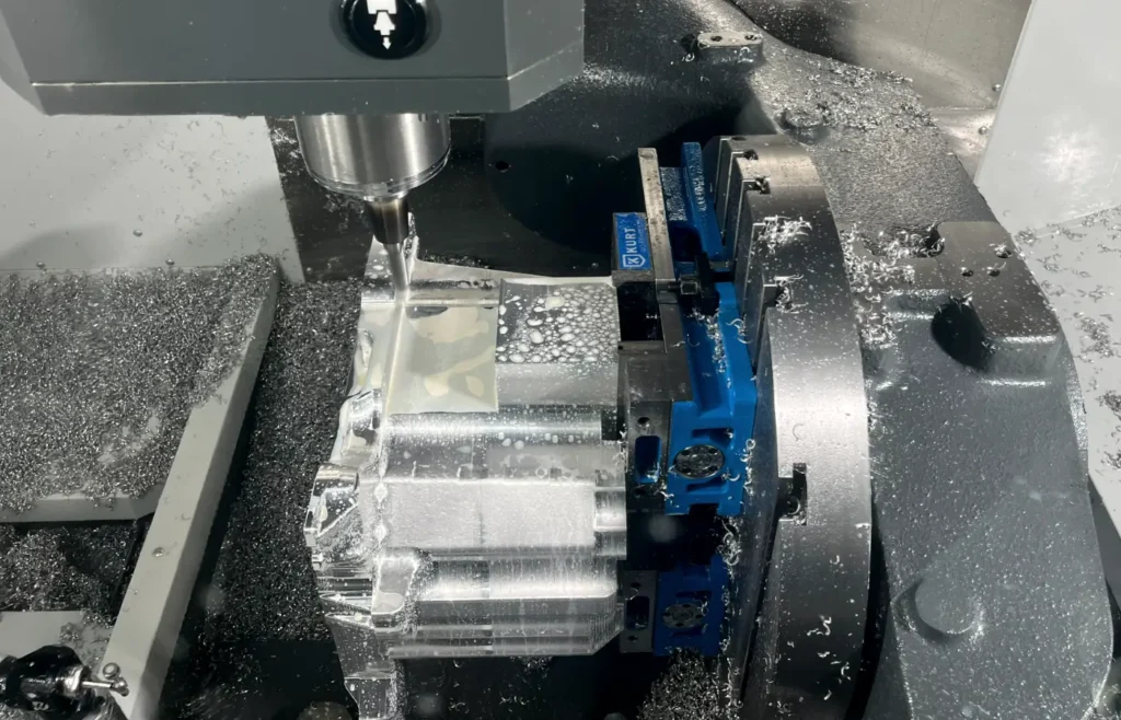
In indexed 3+2 machining, the rotary axes orient the part or tool to a selected angle and remain fixed while X, Y and Z perform the cut. The machine indexes again when another direction is needed.
This suits holes, pockets and faces with defined approach directions. It can reduce manual flipping, keep multiple faces within one datum structure and sometimes permit a shorter tool.
Simultaneous 5-Axis Machining
In simultaneous machining, linear and rotary axes coordinate during cutting, allowing tool orientation to change along the path. This suits changing surfaces and dynamic interference avoidance.
All five axes need not move at every instant. Depending on machine architecture, the tool, workpiece or both may rotate. Autodesk’s official 5-axis machining overview also distinguishes positional and simultaneous strategies by how the axes move during cutting.
Practical Comparison
A finished-part photo or a tilted workpiece does not prove that simultaneous cutting occurred. The programmed motion and required geometry determine the process.
Two Real Parts That Required Different Routes
These examples show why complex aluminum parts may follow different routes.
Case 1: A 6061-T6 Multi-Sided Prototype Produced with 3-Axis and Indexed 3+2 Machining
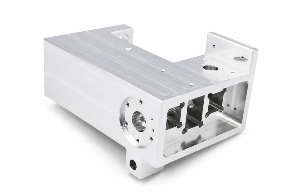
This as-machined 6061-T6 prototype contains holes and fixed-direction pockets on several faces. The feature directions were discrete rather than continuously changing, so a combination of 3-axis and indexed 3+2 operations was selected.
Indexing reduced manual flipping and helped maintain relationships between features on different faces. Continuous rotary-axis movement was not required during the main cutting paths. Verification used CMM inspection, thread gauges and pin gauges.
The industry, dimensions and numerical tolerances are omitted because they are not part of the approved public information. Multiple orientations alone did not make simultaneous motion necessary.
Case 2: A 6061-T6 Automotive Component Using 3-Axis and Simultaneous 5-Axis Machining
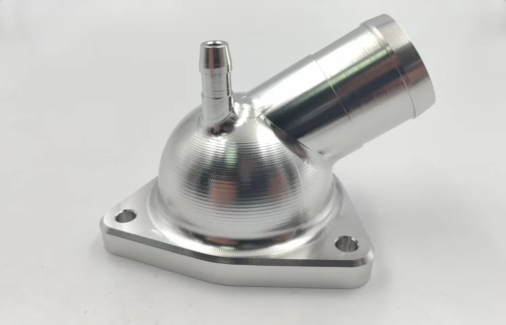
This low-volume automotive component was machined from 6061-T6 and supplied with an as-machined finish. Its geometry includes a continuous spherical surface, two angled ports and blended transition surfaces between the ports and the main body. It also contains interconnected through holes with different surface normals.
The route combined 3-axis operations with simultaneous 5-axis machining. Simultaneous motion was required for the spherical geometry and transition surfaces between both ports and the main body, where tool orientation had to change along the path.
CMM inspection and thread gauges were used for the agreed scope. No dimensions, tolerances or cycle times are claimed here.
The central rule is to choose the strategy feature by feature. Multi-sided geometry may suit 3+2, while selected continuous surfaces may justify simultaneous motion.
Five Engineering Factors That Determine the Route
1. Does the Required Tool Orientation Stay Fixed?
Divide the model into features. If holes, pockets and faces can be completed from fixed directions, indexed 3+2 is usually the first option.
For a freeform surface, evaluate simultaneous machining if fixed-angle regions cause poor transitions, access problems or excessive tool extension.
2. Can the Cutter and Holder Reach the Geometry Safely?
Tool-tip access is not enough. The cutter, holder and spindle nose must clear the part and fixture throughout the path.
Another indexed angle may solve interference. If no fixed angle maintains clearance, dynamic tool-axis change may be required. Verify the complete setup.
Long tools can reduce rigidity and increase vibration. Tilting may permit a shorter assembly, using 3+2 or simultaneous motion as the required angle dictates.
3. How Are the Functional Datums and Cross-Face Features Related?
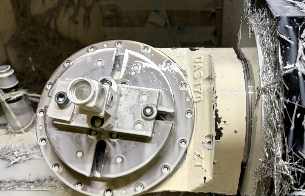
Five-axis equipment can reduce repositioning, but it cannot correct an ambiguous datum scheme. The drawing must identify the surfaces and axes that establish function.
When features on different sides share controlled relationships, one setup may reduce datum transfer. Use 3+2 for fixed directions and add simultaneous motion only where required.
Manufacturing and inspection should reference the same functional relationships.
4. Does Surface Continuity Control Function or Appearance?
For a complex surface, clarify whether shape, profile, flow, sealing, contact or appearance controls acceptance.
Fixed-angle toolpaths may leave transitions. Simultaneous motion can maintain changing orientation where profile or blending matters, although finish still depends on toolpath spacing, cutter geometry and process stability.
Identify critical continuous surfaces and areas where blend lines or tool marks are restricted.
5. Can the Result Be Inspected Reliably?
Process and inspection planning should happen together. The route must support verification against controlled requirements.
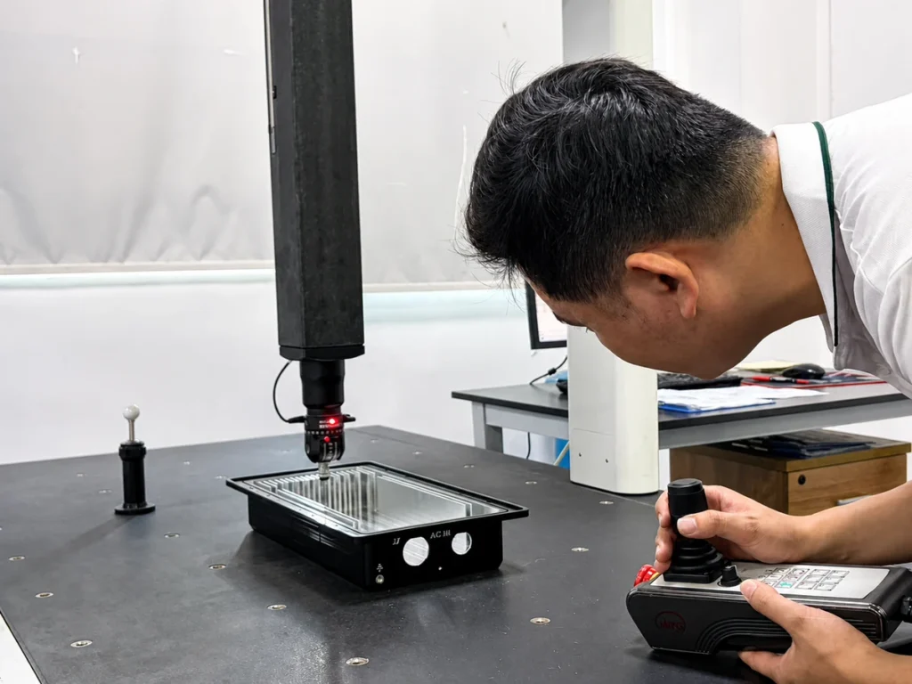
CMM measurement may suit cross-face relationships and profiles, while pin, bore or thread gauges may suit specific features. Confirm access, datums and report scope before machining. For more detail, review the CNC machining inspection guide.
Why Simultaneous 5-Axis Machining Is Not Automatically the Better Process
Simultaneous motion is a capability, not a quality grade.
It is not automatically more accurate. Accuracy also depends on calibration, workholding, cutter condition, tool length, material stability, thermal behavior and measurement. Fewer setups may help certain relationships, but coordinated motion brings additional kinematic and verification requirements. Feature-specific requirements should be reviewed against the drawing and the applicable manufacturing tolerance guidance.
It is not automatically faster. Simultaneous paths may improve access, yet they can require more programming, simulation and feed control. An indexed operation may be more efficient for a fixed-direction feature.
It does not guarantee better finish. Surface quality depends on cutter geometry, step-over, feed, vibration, stock allowance and finishing strategy.
It does not eliminate every setup. Clamping faces, inaccessible areas and part release may still require another operation.
The engineering objective is not to maximize axis movement. It is to meet the drawing reliably with a controlled and inspectable process.
Compare Total Manufacturing Cost, Not Only Machine-Hour Rate
The lowest machine-hour rate may not produce the lowest finished-part cost. Compare all work required to manufacture and verify the component.
Important cost elements include:
- CAM programming, tool-axis control and post-processing
- Collision checking and machine-motion verification
- Fixtures, soft jaws and setup preparation
- Number of setups and repeated datum establishment
- Tooling, overhang, tool life and finishing passes
- Cutting time and machine utilization
- In-process checks and final inspection
- Finishing, masking and post-finish verification
- Scrap risk, rework risk and process documentation
- Quantity, revision stability and repeat-production requirements
Indexed 3+2 is often efficient for fixed-direction features. Simultaneous machining can justify added programming when it avoids an impractical long tool or produces geometry that fixed orientations cannot handle reliably.
Repeat production adds fixture stability, revision control and inspection frequency to the comparison. A prototype may give more weight to feasibility and lead time. Neither method has a universal cost advantage.
Three Common Geometry Scenarios
Scenario 1: Multi-Face Holes and Pockets with Fixed Directions
Consider a housing with holes, counterbores and pockets across several faces. Each feature has a defined normal direction and adequate holder clearance.
This is a typical 3+2 application. The rotary axes orient the part, remain fixed during cutting and then move to the next direction. The route can reduce handling while maintaining cross-face relationships.
Scenario 2: A Continuously Changing Surface or Blended Transition
Consider a spherical housing or a transition between angled ports and a main body. The surface normal changes continuously, and fixed orientations would create access problems or undesirable transitions.
This supports evaluating simultaneous machining. Tool orientation can change with the path to follow the surface and manage clearance. Machine-specific verification remains essential.
Scenario 3: A Mixed Part with Both Feature Types
A 3-axis vs 3+2 vs 5-axis machining comparison is especially useful for mixed parts. Many components combine accessible planes, fixed-direction holes and selected continuous surfaces.
A hybrid route may use 3-axis operations for open features, indexed 3+2 for fixed directions, and simultaneous motion only for continuous or clearance-limited regions.
From CAD Model to Machining-Route Decision
A reliable decision follows a structured review rather than a quick judgment based on overall part shape.
Step 1: Confirm the Controlled Inputs
Confirm the latest 3D model, controlled drawing, revision, units, material, quantity, finish and inspection scope. Resolve model and drawing conflicts before programming.
Step 2: Identify Functional Features and Datums
Mark critical features and cross-face relationships. Establish the functional datums and how they will be created and inspected.
Step 3: Classify Feature Directions
Separate fixed-direction features from surfaces requiring changing orientation. One complex region does not make every operation simultaneous.
Step 4: Review Cutter, Holder and Fixture Clearance
Check each orientation with the complete tooling and fixture. Compare alternate indexed angles and shorter tools before adding simultaneous motion.
Step 5: Compare Setup Concepts
Determine which features share one datum structure, where clamping is possible and whether another operation is unavoidable. Consider support and distortion.
Step 6: Plan Toolpaths and Verify Machine Motion
Verify stock, holder clearance, rotary limits, fixture interference and safe transitions using the actual machine configuration and approved postprocessor.
Step 7: Match Inspection to the Requirements
Define how critical dimensions, GD&T, threads and profiles will be measured. Align manufacturing and inspection datums before production.
These principles also appear in the CNC design for manufacturability guide.
What Information Helps Determine the Right Route?
Process selection requires more than a photograph or overall dimensions. Provide the following information.
Current 3D Model and Controlled Drawing
Provide the latest STEP model or another agreed solid format with the controlled drawing, revision and units. The model supports geometry review, while the drawing identifies tolerances, datums, GD&T and acceptance requirements.
Critical Continuous Surfaces
Identify surfaces and transitions that must remain continuous. State where sectioning, blend lines or tool marks are restricted and which functional or appearance surfaces need protection.
Datum and Cross-Face Relationships
Define the functional datums for features on different orientations. This determines whether reduced repositioning has value and how relationships will be inspected.
Deep Cavities and Restricted Areas
Mark deep pockets, hidden faces, undercuts, narrow entrances and keep-clear zones. Provide relevant assembly geometry when it limits tool access.
Material and Stock Requirements
State the complete grade and condition, such as 6061-T6, plus any controlled stock form. Do not permit substitution without written approval.
Quantity and Project Stage
State whether the project is a prototype, low-volume batch or repeat production, and whether the design is stable. Quantity affects fixture, validation and documentation decisions.
Finishing and Post-Finish Dimensions
Specify downstream processes plus masking, coating thickness, appearance and post-finish dimensional requirements. These may change allowances, sequence and inspection.
Inspection and Documentation Scope
Define required dimensional or CMM reports, first-article records, material certificates, conformity documents and traceability. Inspection access may influence the route.
Delivery Requirement
Provide the target ship date and destination so procurement, production, finishing, inspection and logistics can be planned.
At minimum, submit the current model, controlled drawing, material, quantity, finish, critical surfaces and datums, inspection scope and target delivery. These inputs distinguish fixed-direction features from those requiring changing orientation.
Choose the Least Complex Route That Reliably Meets the Function
A sound 3+2 vs simultaneous 5-axis machining decision starts by recognizing that the two methods solve different geometry and access problems. They are not higher and lower quality grades.
If features have defined directions and adequate clearance, evaluate indexed 3+2 first. It can reduce manual repositioning and datum transfer.
If tool direction must change during cutting for surface continuity or holder clearance, simultaneous motion may be necessary. Mixed parts may combine all three strategies.
Before selecting the route, ask five questions:
- Is tool orientation fixed during each cut?
- Can the cutter and holder reach safely from a fixed angle?
- Do cross-face features share controlled datums?
- Does a critical surface require changing orientation?
- Can the planned inspection verify the process?
The best route is the one that satisfies function, drawing and inspection requirements without unnecessary process complexity. This is also the practical answer to when to use 5-axis machining: use it where orientation or access creates a verified manufacturing benefit, not simply because the part looks complex.
Frequently Asked Questions
Is indexed 5-axis machining the same as 3+2 machining?
In most manufacturing contexts, yes. Both terms describe using the rotary axes to position the part or tool at a selected angle, then holding those axes fixed while the three linear axes perform the cut. Terminology can vary by supplier, so confirm the intended axis motion when reviewing a quotation.
Does a surface with changing normals always require simultaneous 5-axis machining?
No. Changing surface normals alone do not determine the process. An accessible surface may still be machined with 3-axis or indexed 3+2 toolpaths if the required finish and geometry can be achieved. Simultaneous motion is justified when the cutter orientation must change continuously for access, clearance or surface control.
Can one part use 3-axis, indexed 3+2 and simultaneous 5-axis operations?
Yes. Mixed geometry commonly uses 3-axis for open features, 3+2 for fixed directions and simultaneous motion for selected continuous surfaces.
Is simultaneous 5-axis machining always more accurate?
No. Accuracy also depends on calibration, workholding, tool length, material stability, cutting strategy and inspection. Simultaneous motion requires reliable kinematic control and verification.
Is simultaneous 5-axis machining always more expensive?
Not necessarily. It may add programming and simulation but improve access or avoid an impractical setup. Compare total process cost, not only machine-hour rate.
How are multi-directional holes and continuous surfaces inspected?
The drawing determines the method. CMM may evaluate cross-face relationships and profiles, while pin, bore and thread gauges suit specific features. Define datums and report scope before production.
What files should be submitted for review?
Submit the latest STEP model or agreed solid format, controlled drawing, material, quantity, finish, critical-feature and inspection requirements, target date and destination. Highlight continuous surfaces and cross-face relationships.
Unsure Whether Your Part Needs Indexed 3+2 or Simultaneous 5-Axis Machining?
Part appearance alone is insufficient. Samshion reviews geometry, holder access, datums, tolerances, material, finishing and inspection before recommending a route.
upload your CAD files for an engineering review with the model, controlled drawing, material, quantity, finish and inspection scope. Our engineers will evaluate 3-axis, indexed 3+2, simultaneous 5-axis or a controlled combination.
The goal is a stable, inspectable process, not the most complicated motion. Complete requests with clearly defined requirements are typically quoted within 24 hours.