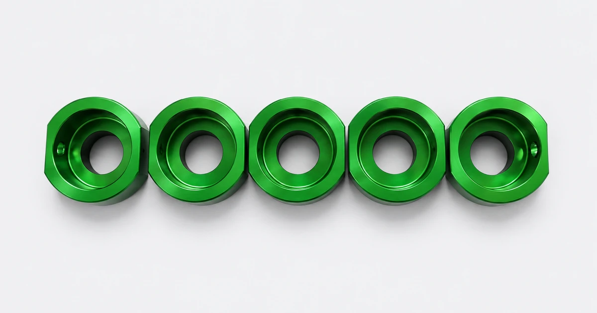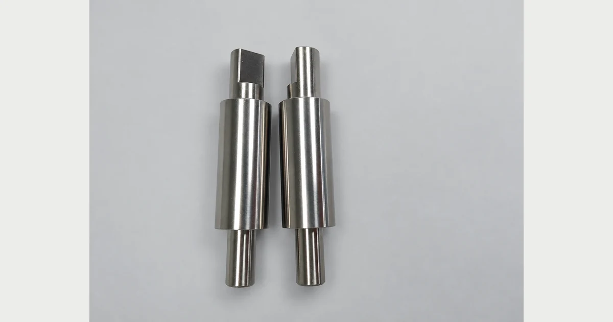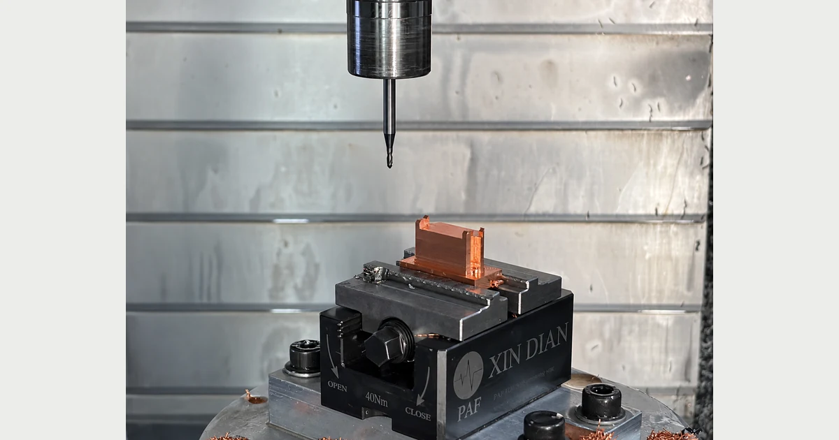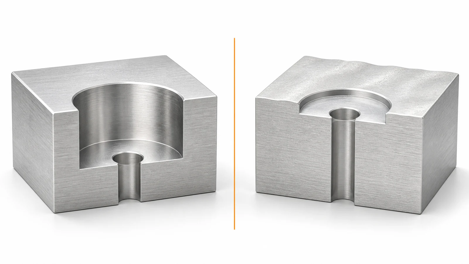
The counterbore vs spotface decision can look simple in a CAD model. Both features create a flat-bottomed circular area around a hole, and both may be produced with similar cutting tools. Their functional intent, drawing definition and acceptance criteria are not necessarily the same.
A counterbore creates a defined cylindrical recess. It is often used when a fastener head, washer, shoulder or mating component must sit at a controlled depth. A spotface removes local material to establish a usable flat seating area. It is commonly applied where the original surface is rough, curved, angled, cast, forged or otherwise unsuitable for direct contact.
Confusing the two can produce a fastener head that sits too high, a seat that cleans up only partially, unnecessary material removal, insufficient remaining wall thickness or an inspection dispute. The correct decision starts with the joint function, not with the name of the cutting tool.
Quick Answer: Counterbore vs Spotface
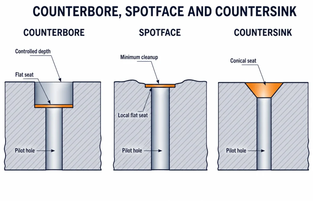
A countersink is different from both. It creates a conical seat for a conical fastener head or another tapered interface. The drawing must distinguish a flat-bottomed counterbore or spotface from a countersink because the tool shape, dimensions and inspection method change.
Scope and Technical Boundary
This article focuses on flat-bottomed seating features around holes. It does not replace a general review of drilling, reaming or boring. Use the CNC hole tolerance guide when the main decision concerns bore size, position, straightness, finish or process selection.
No universal counterbore diameter, spotface diameter, depth or tolerance applies to every fastener and part. The selected fastener standard, joint design, material, available wall thickness, drawing standard and inspection requirement control the final definition. Do not select a recess from a generic online chart alone. Confirm the actual fastener standard, head diameter and height, under-head radius, required fit, coating allowance and assembly clearance. The released drawing remains the acceptance basis.
Key Takeaways
- Select the feature from the required fastener or mating function.
- Define the hole, seating diameter, depth or cleanup condition, quantity and machining side clearly.
- Do not assume the feature name alone controls position, orientation, flatness or surface texture.
- Review tool access before placing a spotface on the back of a wall or inside a housing.
- Check remaining wall thickness, nearby edges, intersecting passages and coating allowance before release.
- Match the inspection method to the controlled characteristic and the actual physical access.
Start With the Fastener and Joint Function
The seating feature transfers clamp load from a fastener head, nut or washer into the part. The design should provide enough contact area for the intended joint without removing more material than necessary. If only part of the head or washer contacts the surface, the joint may seat unevenly or change during tightening.
Use a Counterbore When Depth Is Part of the Function
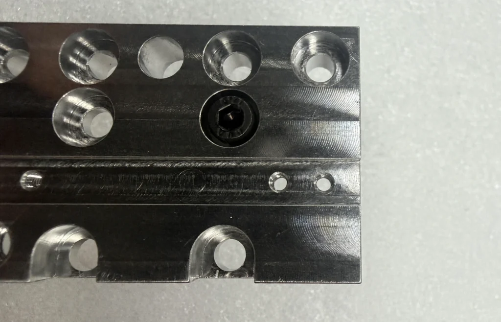
A counterbore is appropriate when a cylindrical item must enter a defined recess. Common examples include a socket-head screw that must sit below, flush with or close to the surrounding surface, a washer that requires lateral clearance, or a shoulder that locates within a machined step.
Diameter and depth work together. A correct diameter with insufficient depth can leave the fastener proud. Excessive depth can reduce local stiffness, approach another passage or leave too little material below the recess. The bottom corner condition also matters when the fastener or mating component has an under-head fillet or sharp edge.
Use a Spotface When the Main Need Is a Flat Seat
A spotface is appropriate when the existing surface cannot provide reliable contact. It may clean up a casting boss, flatten a local area on a curved housing or create a consistent bearing face around a clearance hole.
The design question is not simply how deep the cutter should travel. It is whether the required seating diameter becomes sufficiently flat and continuous without excessive material removal. Under ASME Y14.5 drawing practice, an unspecified spotface depth means the minimum cleanup needed to produce the specified flat diameter. If axial height, remaining wall thickness or fastener stack-up matters, specify the depth or remaining material explicitly. Where a surrounding fillet remains, the specified spotface diameter refers to the usable flat land, not the outside of the fillet.
Use a Countersink for a Conical Interface
A countersink matches a conical fastener or tapered interface. Its included angle and effective diameter influence how the fastener seats. Replacing a specified counterbore with a countersink, or the reverse, changes the contact geometry and is not an interchangeable shop decision.
What the Drawing Should Define
ASME Y14.5-2018 (R2024) includes counterbore, spotface, countersink and depth symbology within its product-definition practices. ISO 15786:2008 addresses simplified representation, dimensioning and tolerancing of holes and counterbores in ISO-based technical drawings. Always identify the drawing standard and edition because symbol construction and interpretation can differ between systems and revisions. Do not combine ASME and ISO conventions into an assumed universal callout or treat a CAD hole label as the complete requirement.
The controlled drawing should define the characteristics that matter to assembly and inspection.
A conceptual callout may follow this structure:
[quantity] × [through or blind hole], counterbore [diameter] × [depth], from [identified side]
or:
[quantity] × [hole], spotface [diameter], from [identified side], with [required seating or cleanup condition]
These are information structures, not standard-specific callout examples. The released drawing should use the symbols, units and conventions required by its governing standard.
Do Not Assume Geometry That the Drawing Does Not Control
A counterbore symbol does not automatically communicate every functional relationship. If the recess must be positioned from datums, perpendicular to a mounting face, coaxial with a precision hole or controlled for flatness, the drawing should state the applicable requirement.
The same principle applies to a spotface. A locally flat surface can still be tilted relative to the hole axis or the assembly datum. When a washer or bolt head needs uniform contact, the designer should define the relationship that actually protects the joint instead of relying on the word spotface alone. Our guide to datum-based position and perpendicularity explains how functional relationships can be communicated without assigning unnecessary controls to every surface.
Choose the Machining Route From the Complete Part
Counterbores and spotfaces may be machined with an interpolating end mill, a dedicated counterbore or spotface cutter, a boring tool or a combined process. Dedicated tooling can be effective for repeated features, while interpolation provides diameter flexibility. Boring may be considered when diameter control, surface condition or feature size justifies it. Tool choice still depends on material, access, diameter, depth, quantity, tolerance, interrupted cutting and required evidence.
The drawing defines the finished feature. It does not prescribe one universal cutting method unless the process itself is a controlled requirement.
Official tooling guidance such as the Seco spot-facing mill information illustrates that spotfacing is treated as a distinct cutter application. The tool supplier’s operating limits must be reviewed for the actual machine and material rather than copied as a universal process rule.
At Samshion, the route is selected from the actual model and drawing. Front-side and reverse features can be evaluated, and the operation may use end-mill interpolation, dedicated tooling, boring or more than one method. The selected route must create the required seat while preserving access, surrounding material and inspection capability. Our custom CNC milling services explain how tool access, workholding and inspection are reviewed together before production.
Operation Sequence Matters
The primary hole may be drilled before the seating feature when it provides tool guidance or establishes the feature center. In another part, preparing the seat first may create a stable entry surface for the hole. A blind feature, interrupted surface or tight relationship can require a different sequence.
The planner should also consider where burrs will form, how chips will leave the recess, whether the tool can reach the floor without holder interference and whether the part remains supported while the local material is removed.
Review Curved, Angled and Uneven Surfaces Separately
A cutter entering a curved, drafted or uneven surface may contact one side before the other. This interrupted engagement changes cutting load and can leave only partial cleanup at a nominal depth. Cutting deeper until the full diameter cleans up may remove more material than the designer expected.
For these surfaces, review:
- the minimum and maximum starting material condition;
- whether the complete seating diameter must clean up;
- the final seat orientation relative to the hole and assembly datum;
- the deepest possible material removal;
- the remaining wall thickness at the lowest point;
- local interruption from ribs, bosses, edges or nearby holes;
- cutter and holder clearance throughout the operation.
If the required seat is angled relative to an available setup, the route may need an additional orientation, indexed machining, a dedicated fixture or a multi-axis approach. Simply plunging deeper from the wrong direction does not create the intended bearing plane.
Plan Back Counterboring and Reverse Spotfacing Before Release
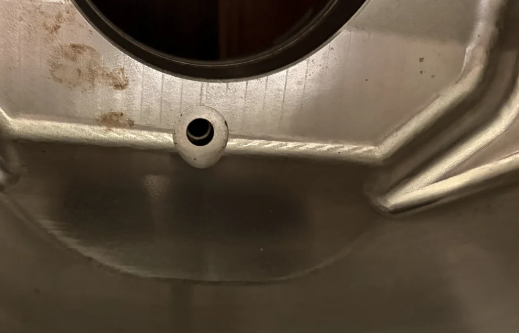
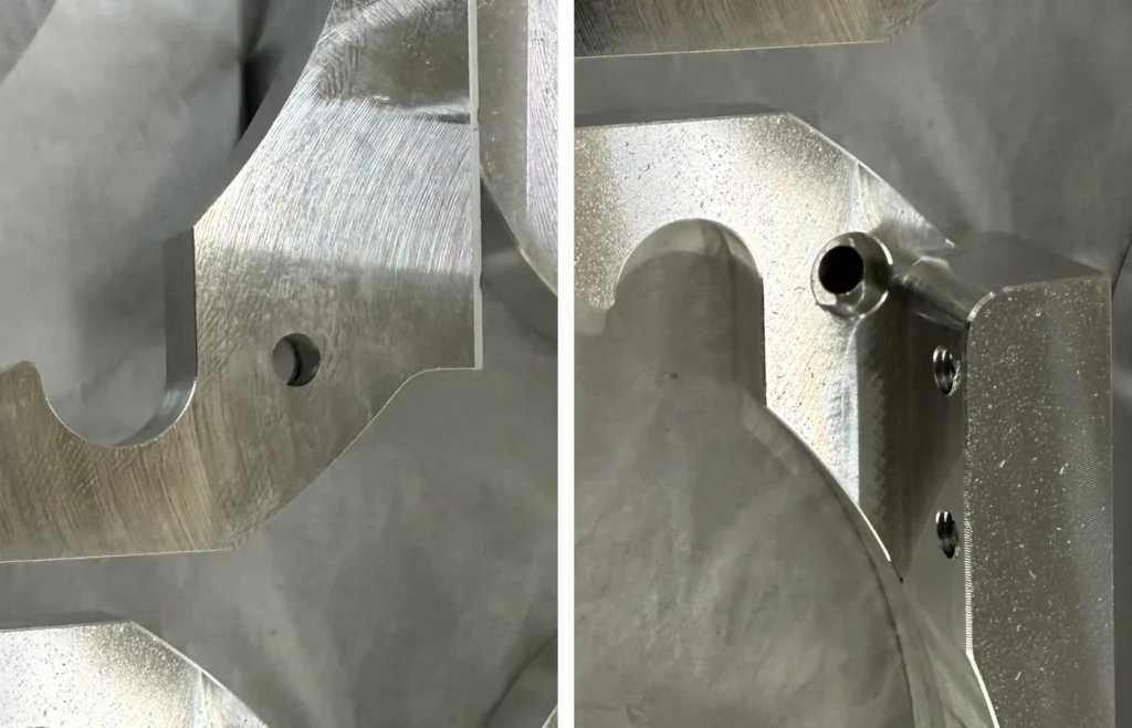
A reverse spotface lies on the far side of a wall or flange relative to the available spindle approach. The operation may require the part to be turned over, another setup, an angled tool approach or a dedicated tool that passes through the primary hole and cuts on the back side.
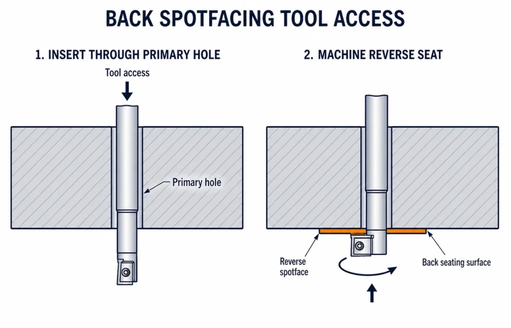
Specialized tooling exists for this purpose. HEULE’s official counterboring tool information describes systems that pass through the existing bore and machine the reverse side without turning the workpiece. This demonstrates the process concept, but it does not mean every diameter, ratio, material or interrupted surface fits one tool family.
Before specifying a reverse feature, provide:
- the primary hole diameter available for tool passage;
- the required reverse-seat diameter;
- wall thickness and seat depth;
- clearance behind and around the seat;
- material and hardness;
- whether the cut is continuous or interrupted;
- quantity and repeat demand;
- surface texture, flatness and inspection requirements;
- any internal passages or surfaces that must not be touched.
Samshion supports back counterboring and reverse spotfacing, but the method is confirmed case by case. A special tool can sometimes avoid another setup, while reorienting the part may be more practical for a prototype or a feature outside the tool’s operating range.
Protect Remaining Wall Thickness and Nearby Features
A counterbore removes more than the visible top surface. A large diameter or deep recess can approach an outside wall, intersect a side hole, weaken a boss or leave a thin floor above another cavity. The risk is easy to miss in a top view.
Review a section through the complete feature and check:
- material remaining below the recess;
- radial material between the recess and the nearest edge;
- distance to threads, grooves, sealing lands and internal passages;
- the fastener head fillet and required bottom-corner clearance;
- breakout caused by draft, curvature or stock variation;
- local stiffness during clamping and cutting;
- access for deburring and inspection.
There is no universal minimum wall value for every material and joint. Strength, load path, heat treatment, coating, casting allowance and assembly duty can all change the decision.
Control Burrs and Edge Condition
The primary hole, counterbore wall, recess floor and reverse exit can each produce a different burr. A loose burr can prevent full seating, damage a washer, enter an internal passage or contaminate an assembly. An oversized chamfer can also reduce the available bearing area.
The drawing should distinguish between removing a burr and creating a controlled chamfer or radius. Internal intersections and reverse features need an accessible deburring route and a practical verification method. The deburring CNC machined parts guide explains how edge function, access and inspection should be connected.
Account for Surface Finishing and the Final Inspection State
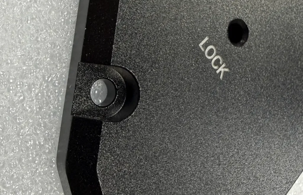
Anodizing, plating, conversion treatment, painting and powder coating can change recess diameter, edge condition, contact behavior or effective depth. A seat may also need masking for electrical contact, grounding, seal performance or metal-to-metal load transfer.
The drawing and quotation should state:
- whether dimensions apply before or after finishing;
- whether the seating face, recess wall or primary hole is masked;
- the permitted coating condition on the fastener interface;
- which dimensions are rechecked after finishing;
- any cosmetic boundary around the spotface or counterbore.
Samshion reviews the finished condition against the drawing when it controls acceptance. Our overview of surface finishing requirements explains the available processes and why masking, functional surfaces and dimensional allowance should be confirmed before processing.
Match Inspection to the Controlled Characteristic
No single instrument verifies every requirement. An accessible diameter with a broad tolerance may suit a caliper or bore instrument. A controlled depth may suit a depth gage or depth micrometer. Position, orientation and related datum requirements may require a CMM or a suitable functional gage.
Mitutoyo’s official depth micrometer information describes depth micrometers intended for measuring recessed depths. The measuring base still needs adequate contact, and the rod must reach the relevant floor without bridging a radius, burr or uneven seat.
For recessed and reverse features, CMM access depends on stylus selection and collision clearance. ZEISS describes L, T, disc and other CMM stylus configurations for bores, recesses, undercuts and difficult-to-access points. A complex probe does not automatically make the result valid. Alignment, point strategy, datum simulation, calibration and feature accessibility still matter.
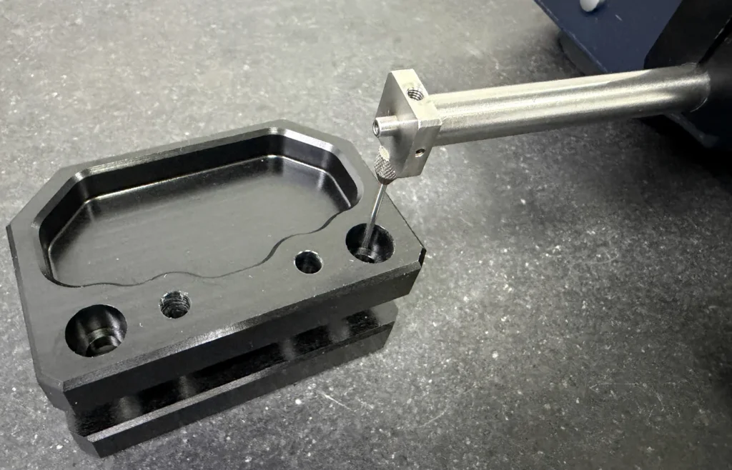
At Samshion, inspection may use calipers, depth gages, depth micrometers, height gages, pin or plug gages and CMM equipment according to feature access and the controlled requirement. The report scope and sampling plan should be agreed before production. The CNC machining inspection guide provides broader guidance on matching characteristics with equipment and records.
Common Problems Seen During Project Review
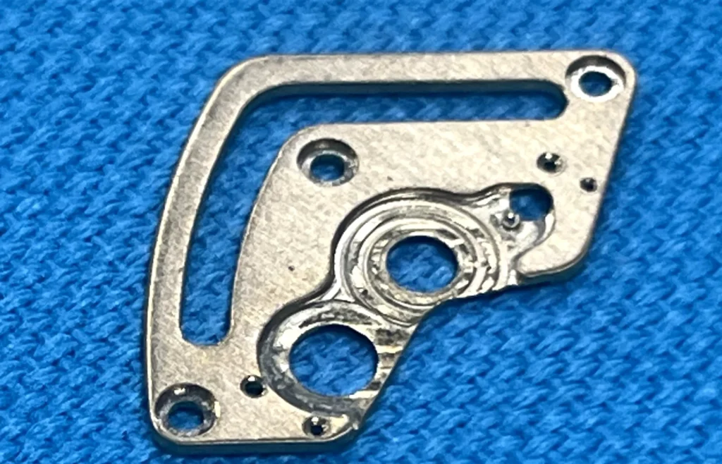
Samshion has encountered each of the following issues in actual quotation or production reviews. The correct response is to clarify the functional requirement before changing the process or drawing.
Cost and Lead-Time Drivers
A small seating feature can add meaningful work when it requires another setup, special tooling or complex inspection. The quotation should reflect the complete route rather than pricing the feature from diameter alone.
Important drivers include:
- number of counterbores or spotfaces;
- range of diameters and depths;
- front, side or reverse access;
- standard tooling versus special or dedicated tooling;
- continuous versus interrupted cutting;
- curved, angled, cast or forged starting surfaces;
- material hardness and tool-wear risk;
- position, orientation, flatness or surface-texture requirements;
- coating, masking and final-condition inspection;
- prototype quantity, repeat demand and inspection reporting.
For a prototype, an additional setup may be more economical than purchasing a dedicated back-facing tool. For recurring production, special tooling may reduce handling and improve consistency. The correct comparison depends on total expected demand and the controlled acceptance requirements.
RFQ Checklist for Counterbores and Spotfaces
Before requesting a quotation, provide:
- The current 3D CAD model.
- A controlled 2D drawing with the governing standard and revision.
- Primary-hole diameter, tolerance and through or blind condition.
- Counterbore or spotface diameter and the required depth or cleanup condition.
- Quantity and the side from which each feature is machined.
- Functional datums, position and orientation controls where required.
- Fastener or mating-component specification when it clarifies the joint.
- Material grade, condition and stock form.
- Required surface treatment, masking and post-finish dimensions.
- Inspection method, report format and sampling requirement if prescribed.
- Current quantity, expected repeat demand and target delivery date.
Request a Counterbore or Spotface Review
Send the complete model and drawing rather than a cropped hole detail. The surrounding wall, fastener envelope, reverse access, nearby passages, finishing route and inspection access can change the manufacturing decision.
Samshion can review front and back counterbores, spotfaces, tool access, remaining material, finishing allowance and verification requirements as part of a CNC milling quotation. When your files are ready, upload your CAD model and controlled drawing with the material, quantity, finish and required documentation.
Frequently Asked Questions
What is the main difference between a counterbore and a spotface?
The physical geometry may look similar, and some tools can produce both. The functional intent differs. A counterbore creates a defined recess, while a spotface creates a local seating surface with limited material removal. The drawing should communicate the intended function and acceptance condition.
Does a spotface need a depth dimension?
Not every spotface is controlled by one fixed depth. Some are defined by the required seating diameter or cleanup condition. If head position, remaining wall thickness or assembly stack depends on depth, state the applicable limit or final condition on the drawing.
Can a spotface be used instead of a counterbore?
Only when the drawing and joint function allow it. A spotface establishes a local flat seat, while a counterbore creates a controlled recess. If the fastener head position or assembly envelope depends on depth, the spotface cannot replace the counterbore without an approved design change.
Which dimensions should be specified for a counterbore or spotface?
Identify the primary hole, seating diameter, applicable tolerance, quantity and machining side. Give a counterbore depth. For a spotface, state whether minimum cleanup is acceptable or whether depth, remaining material, orientation, flatness or surface texture must be controlled.
Can a back spotface be machined without flipping the part?
Sometimes. Dedicated back-facing tools can pass through the primary hole and cut the reverse seat. Feasibility depends on passage diameter, required seat diameter, clearance, material, interrupted cutting and available machine functions. Another setup may still be more practical.
How is counterbore depth inspected?
Depending on size, access and tolerance, inspection may use a depth gage, depth micrometer, height gage, CMM or a dedicated method. The measuring base and contact point must reference the surfaces defined by the drawing.
Should counterbore dimensions apply before or after anodizing or plating?
The drawing should state the required final condition. If coating affects fastener clearance, electrical contact or head position, define masking, dimensional allowance and post-finish inspection before production.
Can counterbores and spotfaces be machined on curved or angled surfaces?
Yes, but the interrupted entry, seat orientation, deepest cut, remaining material and holder clearance must be reviewed. A nominal shallow depth may not clean up the complete seating diameter on a curved or angled starting surface.