
Custom CNC Milling Services for Precision Metal and Plastic Parts
SAMSHION manufactures custom CNC-milled parts in metals and engineering plastics using 3-, 4- and 5-axis machining. Submit your CAD model and drawing for an engineering review and project-specific quotation.
- From One Prototype to Repeat Production
- ISO 9001:2015 Quality Management System
- Lead Times from 3 Days
CNC Milling Capabilities at a Glance
The figures below summarize our equipment, production support, selected tolerance and surface-finish capabilities, and quality controls. Final specifications are confirmed for each project during quotation.
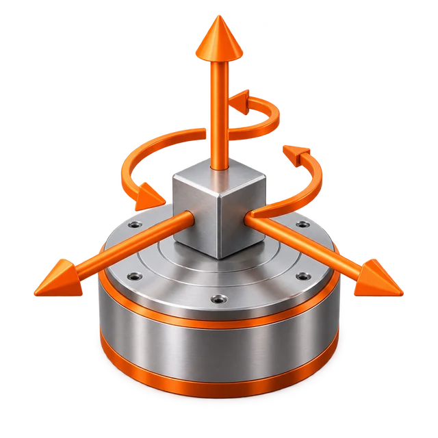
3-Axis, 4-Axis and 5-Axis Milling
We select the machining route according to feature access, setup requirements, datum relationships and production needs. Complex multi-face parts may use 5-axis machining after engineering review.
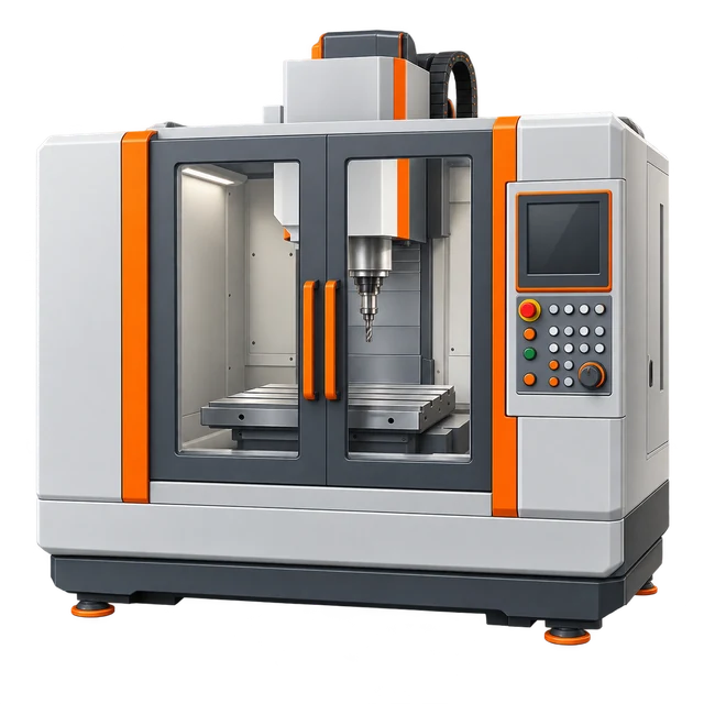
50 CNC Milling Machines
Our facility operates 50 CNC milling machines, including 10 five-axis machining centers, with additional turning and mill-turn support available for combined production routes.
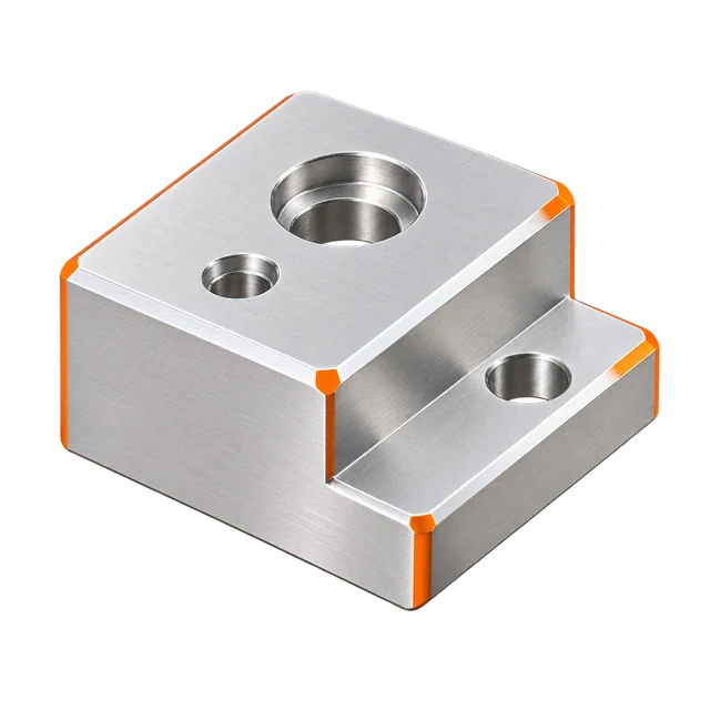
From One Prototype to Repeat Production
We support one-off prototypes, bridge and low-volume builds, and scheduled repeat production, with no fixed minimum order quantity for CNC milling.
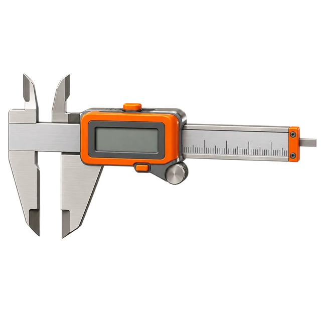
Selected Tolerances to ±0.01 mm
Selected linear dimensions may be quoted to ±0.01 mm when part geometry, material condition, workholding, finishing and measurement capability allow.
Machined Surfaces from Ra 3.2 to Ra 0.4
Ra 3.2 µm is a typical as-machined specification. Selected accessible surfaces can be milled to Ra 0.4 µm when part geometry, tool access, cutting strategy and inspection requirements allow.

ISO 9001:2015 Quality System
Every order receives internal first-off and process-stability checks. Customer-facing dimensional reports, CMM reports, FAI documentation and material certificates are supplied when included in the approved quotation.
What Is CNC Milling and When Should It Be Used?
CNC milling is a subtractive manufacturing process in which rotating cutting tools remove material from a solid workpiece. It can create flat and contoured surfaces, pockets, slots, holes, threads and features distributed across multiple faces.
Milling is generally suited to parts dominated by prismatic or multi-face geometry, particularly when datum relationships, mating surfaces, precision bores or threaded features must be controlled. Predominantly rotational parts are usually better suited to CNC turning, while components combining turned and milled geometry may use a mill-turn route.
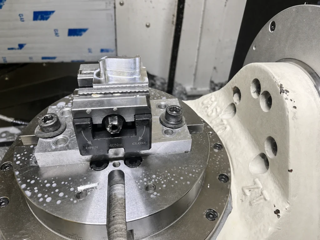
Parts and Features Suited to CNC Milling
CNC milling is well suited to metal and engineering plastic parts that combine flat faces, pockets, bores, threads, contours and features on multiple sides. The most suitable machining plan depends on tool access, workholding datums, wall thickness, pocket depth and dimensional requirements. The production parts below illustrate six types of geometry we commonly review.
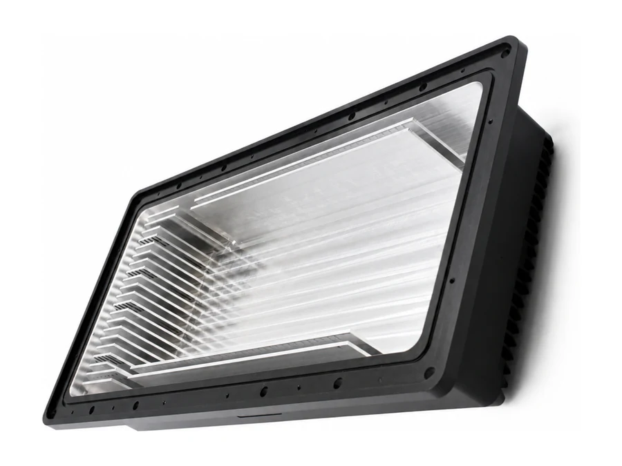
Housings and Cavity Parts
Wireless communication housings often combine large internal cavities, sealing grooves, mounting holes and internal ribs or channels. The part shown has black anodizing on the exterior, while specified internal areas have the anodic layer removed. Tool access, distortion control and finishing boundaries must therefore be planned together.
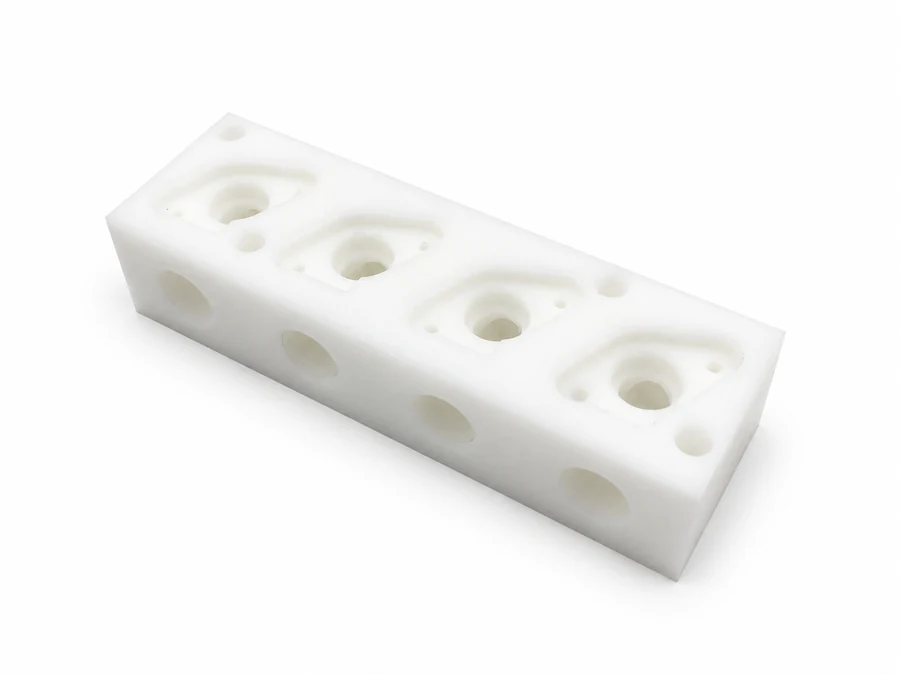
Multi-Sided Hole Patterns and Internal Passages
Medical equipment connectors and channel components may include ports on several faces and intersecting internal passages. Key considerations include hole-to-hole relationships, deburring at passage intersections, internal passage continuity and part cleanliness.
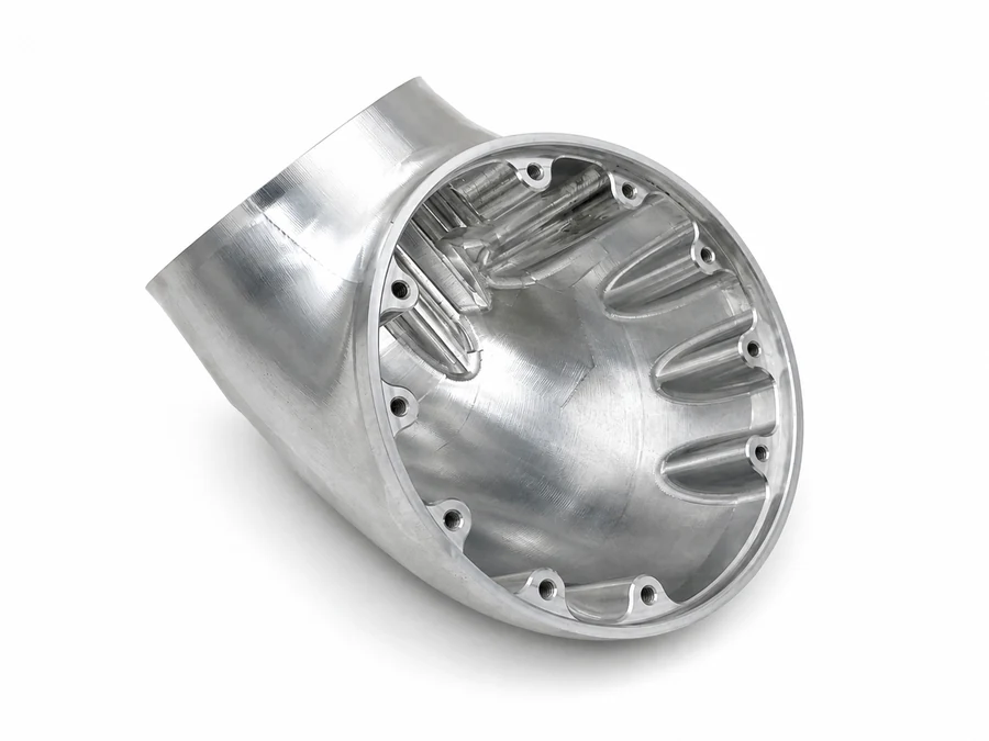
Contoured Housings and Multi-Sided Features
Robot components may combine external contours, internal cavities, circular mounting faces, ribs and threaded holes in different orientations. The machining plan must account for workholding and tool approach while controlling the relationship between hole patterns, mating surfaces and internal and external geometry.
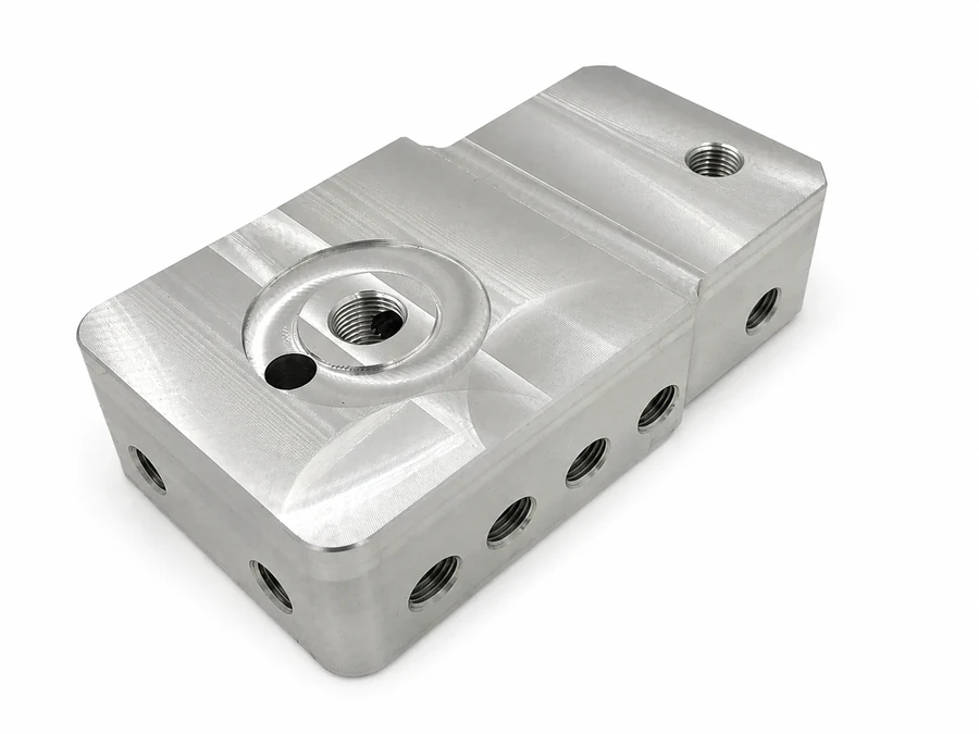
Mounting Blocks and Connector Components
Industrial equipment connector blocks often include threaded ports in multiple directions, mounting faces, locating features and locally contoured surfaces. Machining must control port locations, thread integrity and mating or interface surfaces while removing burrs from every opening.
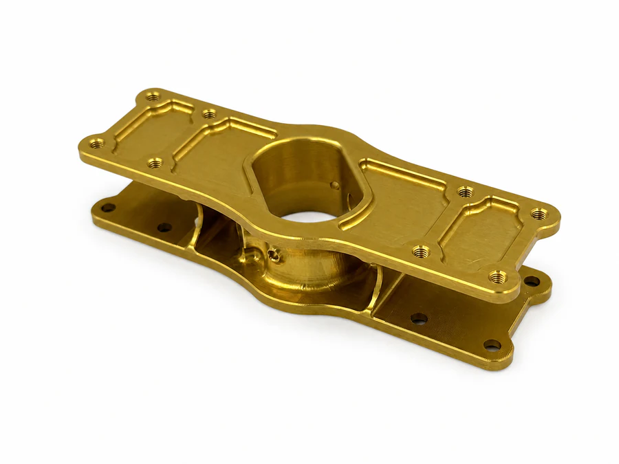
Thin-Wall and Lightweight Structures
Drone components often use thin walls, lightening pockets and ribs to balance weight with structural rigidity. Machining must manage clamping force, material-removal sequence and distortion between setups while maintaining wall thickness, mounting-face flatness and hole locations.
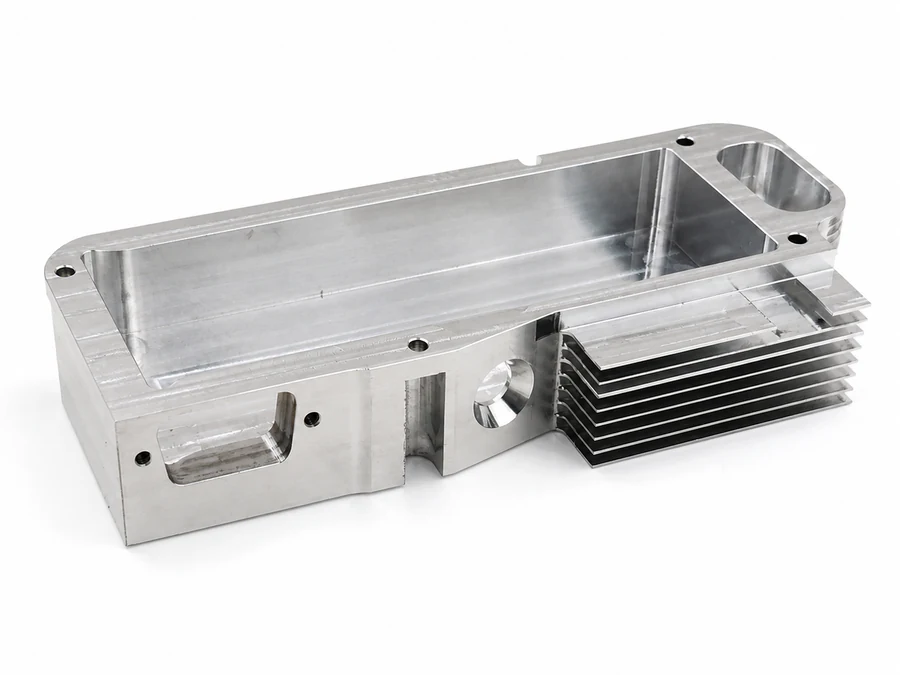
Deep Cavities and Integrated Features
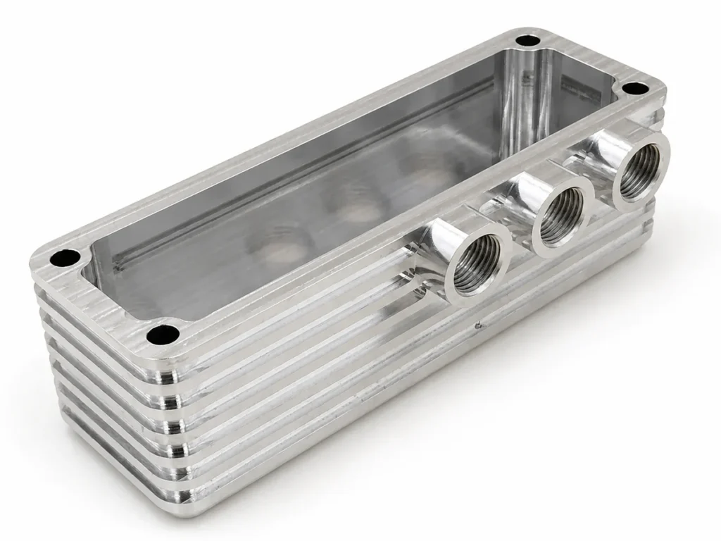
When a part combines a long deep cavity, side openings, hole patterns and closely spaced fins, the machining review must consider tool overhang, vibration, chip evacuation, internal radii and access from multiple directions. A suitable setup and cutting sequence help maintain the stability of the cavity, side walls and fins.
Not sure whether your part is suitable for CNC milling? Upload your CAD files and drawings so our team can review the geometry, material and critical requirements before quoting.
Choosing 3-Axis, 4-Axis and 5-Axis CNC Milling
The appropriate axis configuration is the least complex route that can machine and verify the required features reliably. We select 3-axis, indexed 4-axis or 5-axis machining according to tool access, setup count, datum relationships, surface geometry, tolerance requirements and production quantity.
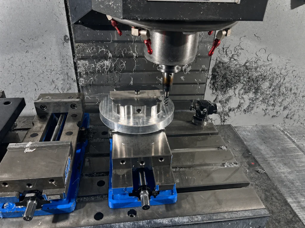
3-Axis CNC Milling
Three-axis milling moves along the X, Y and Z directions and is suitable when the primary features can be reached from one main orientation. It is commonly used for plates, brackets, pockets, holes, slots and planar profiles. Side features may require additional setups, but three-axis machining is often the most economical route when rotary access is unnecessary.
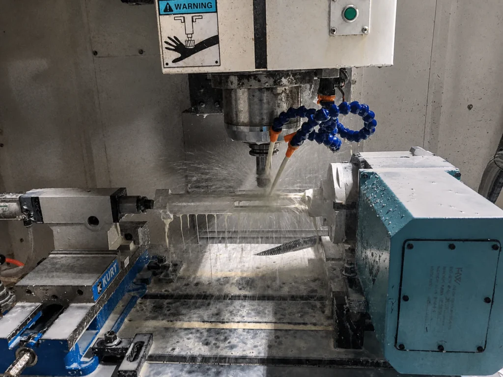
4-Axis CNC Milling
Four-axis milling adds controlled rotation around one axis. It is useful for holes, slots and profiles distributed across several sides or around a cylindrical component. Rotary positioning can reduce manual re-clamping and help maintain related features within a consistent datum strategy, subject to fixture access and machine clearance.

5-Axis CNC Milling
Five-axis machining uses two rotary axes to orient the workpiece or cutting tool. Indexed 3+2 machining can access multiple faces and compound angles, while simultaneous five-axis motion supports continuously changing contours. It is suitable for multi-sided housings, deep or angled features and complex surfaces, although some parts may still require more than one setup.
For parts requiring indexed 3+2 machining, simultaneous multi-axis motion or complex tool access, explore our dedicated 5-axis CNC machining service.
Workholding, Datums and Setup Planning for CNC Milling
Workholding and datum planning affect part stability, feature access and the relationships maintained between setups. Before programming, we define how the stock will be located, supported and clamped, how drawing-defined datum relationships will be maintained, and where in-process checks are required.
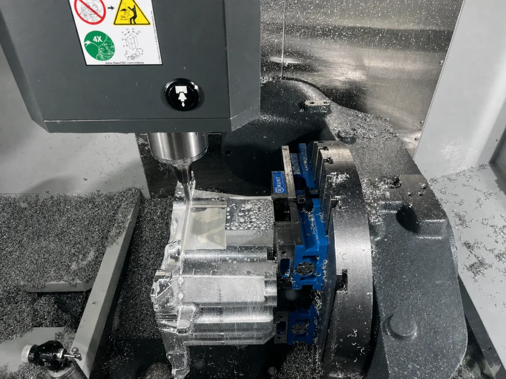
The workholding approach, datum sequence, features assigned to each setup and necessary in-process inspection points are defined before programming and first-off machining begins.
Match Workholding to Part Geometry
We commonly use machine vises, hold-down clamps and profile-matched supports or fixtures. The choice depends on stock geometry, available clamping areas, cutting forces and the faces that must remain accessible.
Protect Thin Walls from Clamping Distortion
Clamping points are kept away from thin-wall sections where practical. Contoured support blocks or form-fitting fixtures can be added to increase the support area and reduce clamping distortion and machining vibration.
Transfer Datums with Bores or Drawing Datums
When a part must be flipped, previously machined precision bores or drawing-defined datum surfaces can be used for relocation. This helps maintain the feature relationships established in the previous setup.
Reduce Setups and Datum-Transfer Risk
For features distributed across multiple faces, five-axis machining can complete more surfaces in one setup. This can reduce part flipping, datum-transfer error, tolerance stack-up and the scrap risk associated with multiple three-axis setups.
CNC Milling Challenges We Review Before Production
CNC milling difficulty depends on more than the specified tolerance. We review feature geometry, tool access, material behavior and inspection requirements to identify risks that can affect machining stability and verification.
Cavity depth, opening width, tool overhang, effective flute length, internal radii, chip evacuation and access to floors and sidewalls.
Control tool extension, machine the cavity in stages, separate roughing and finishing operations, and maintain effective coolant delivery and chip evacuation.
Wall thickness, unsupported length, feature height, available support areas, clamping points and the risk of movement as material is removed.
Keep clamping forces away from thin sections where practical, add contoured support when necessary, and plan the machining sequence and finishing allowance to reduce distortion.
Bore tolerance, position, coaxial relationships, drawing datums, mating requirements and available inspection access.
Select the bore-finishing method, such as reaming or boring, according to the part geometry and tolerance requirement. Pin gauges, plug gauges, bore gauges or CMM inspection may be used as appropriate.
The relationship between the specified corner radius, cavity depth, cutter diameter, effective flute length and required tool reach.
Confirm that a practical cutter can reach the feature without excessive overhang. When the specified radius requires an impractically small or long-reach cutter, we recommend increasing it where the design allows.
Holes, threads, mounting faces, sealing surfaces and other features distributed across different directions in relation to the drawing datums.
Complete more features in a single five-axis setup where appropriate. When a part must be flipped, use previously machined precision bores or drawing-defined datum surfaces for relocation.
Large-volume material removal, thin floors, local stiffness, clamping support and possible flatness changes after the part is released.
Use staged roughing, retain finishing allowance, re-clamp the part before final machining when required, and verify the finished flatness.
The machining sequence, setup conditions, cutting-tool selection and necessary in-process inspection checkpoints for critical features are defined before programming and machining begin, rather than relying only on final inspection.
Real CNC Milling Examples
These examples are based on parts manufactured in our workshop. Each case presents the confirmed material, machining route, production type, key manufacturing challenge and inspection approach.
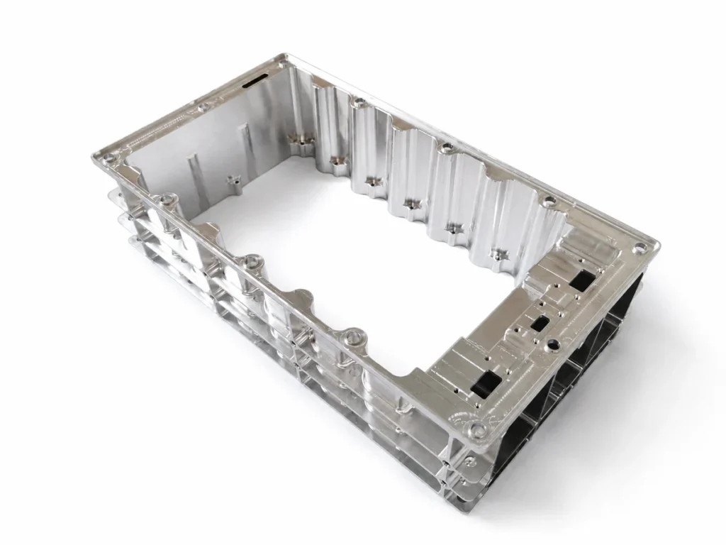
Five-Axis Machined 6061-T6 Communication Housing
As-machined 6061-T6 communication housing produced in a low-volume batch using five-axis CNC milling.
Material
Aluminum 6061-T6
Machining Process
5-Axis CNC Milling
Surface Finish
As Machined
Production Type
Low-Volume Production
Critical Requirements
Flatness: 0.05 mm
Surface Roughness: Ra 0.8 μm
Key Machining Challenge
This communication housing combines a large internal cavity with holes, threaded features and other interfaces distributed across multiple faces. Because the enclosure requires sealing, the perimeter mating surface must maintain 0.05 mm flatness and Ra 0.8 μm surface roughness.
Machining Approach
Five-axis CNC milling was selected to reach features from multiple directions while reducing part flips and datum transfers. Fewer setups help minimize errors caused by repeated clamping and provide a more stable machining condition for the sealing surface and related interface features.
Inspection
A CMM was used to verify the controlled dimensions and sealing-face flatness. Surface roughness was checked with a roughness tester, while threaded features were verified using thread gauges.
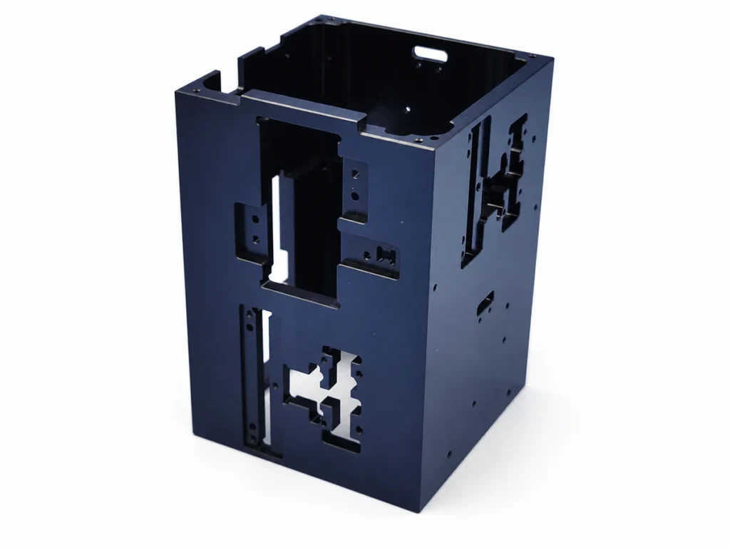
Five-Axis Machined Blue-Anodized 6061-T6 Prototype Housing
One-piece 6061-T6 prototype housing produced by five-axis CNC milling and finished with blue anodizing.
Material
Aluminum 6061-T6
Machining Process
5-Axis CNC Milling
Surface Finish
Blue Anodizing
Production Type
Prototype
Critical Requirements
Small Threaded Holes and Multi-Face Openings
Key Machining Challenge
This one-piece housing combines a deep internal cavity with cutouts, slots and small threaded holes distributed across multiple faces. The machining plan must maintain the relationships between these features and the geometry surrounding the large openings.
Machining Approach
Five-axis CNC milling provides access to the internal cavity and features on different faces with fewer part repositioning steps. This supports more consistent feature relationships and reduces the alignment risk associated with repeated setups.
Inspection
A CMM was used to verify the controlled dimensions and positional relationships between features. Small threaded holes were checked using thread gauges.
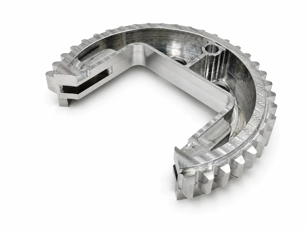
3-Axis Machined 7075-T5 C-Shaped Transmission Gear Component
As-machined 7075-T5 C-shaped transmission gear component produced as a prototype using three-axis CNC milling.
Material
Aluminum 7075-T5
Machining Process
3-Axis CNC Milling
Surface Finish
As Machined
Production Type
Prototype
Critical Requirements
High Gear Accuracy
Key Machining Challenge
The final C-shaped geometry combines external gear features with curved internal surfaces, stepped sections, bores and raised bosses. The primary challenge is maintaining the required gear accuracy and the dimensional relationships between the outer profile and internal features.
Machining Approach
Three-axis CNC milling was used to machine the accessible profiles, stepped surfaces and internal features from controlled orientations. The machining plan focused on maintaining a consistent datum relationship between the outer gear geometry and the internal features.
Inspection
A CMM was used to verify the controlled dimensions and positional relationships of the gear and internal features.
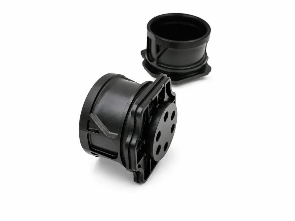
Five-Axis Machined Black POM Component for Low-Volume Production
Two samples of the same black POM component produced in a low-volume batch using five-axis CNC milling.
Material
Black POM
Machining Process
5-Axis CNC Milling
Surface Finish
As Machined
Production Type
Low-Volume Production
Critical Requirements
Deformation Control
Key Machining Challenge
Black POM can deform under clamping pressure and during material removal. The curved body, ribs, flange features and holes on multiple faces require a machining plan that maintains the intended geometry without introducing unnecessary stress or distortion.
Machining Approach
Five-axis CNC milling provides access to the curved surfaces, internal features and holes from multiple directions while reducing repeated repositioning. The workholding and machining sequence were planned to limit clamping deformation and maintain consistent feature relationships.
Inspection
A CMM was used to verify the controlled dimensions and positional relationships after machining.
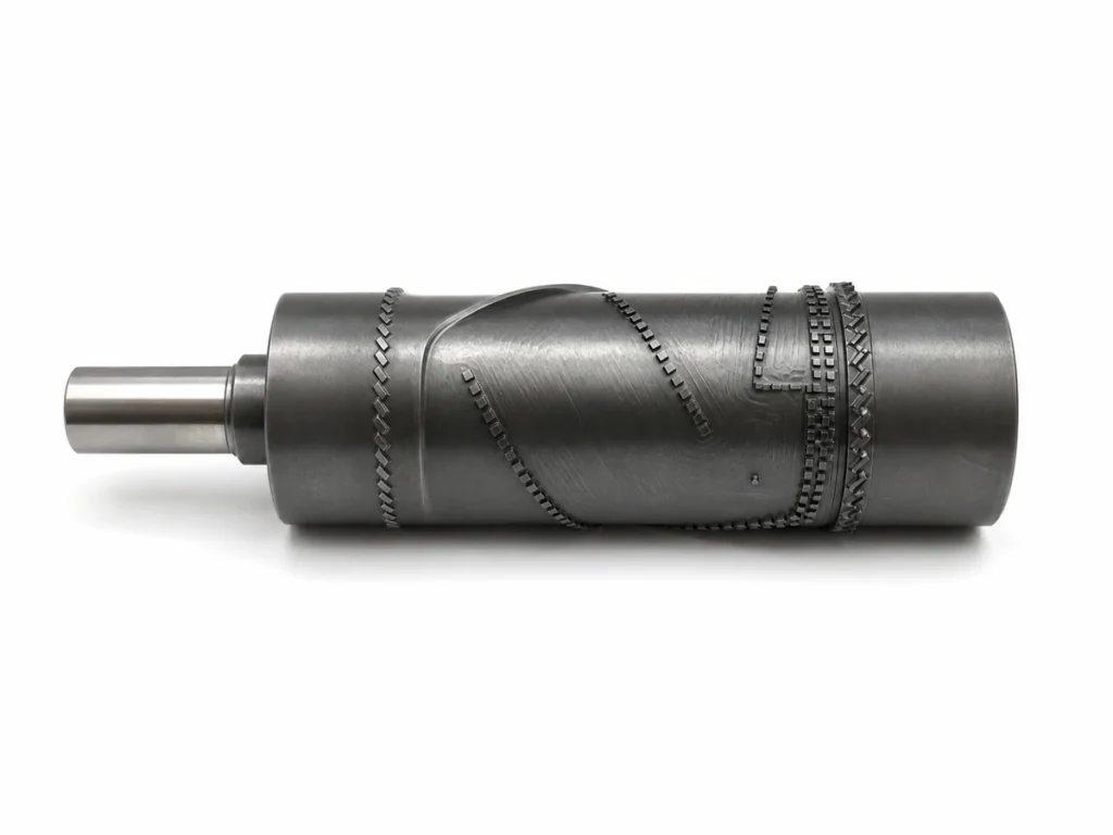
Turned and 4-Axis Milled Heat-Treated D2 Tool-Steel Component
Complete heat-treated D2 tool-steel component produced in a low-volume batch using CNC turning and four-axis CNC milling.
Material
Heat-Treated D2 Tool Steel
Machining Process
CNC Turning and 4-Axis CNC Milling
Surface Finish
As Machined
Production Type
Low-Volume Production
Critical Requirements
Complex Features Around a Cylindrical Surface
Key Machining Challenge
The complete component combines concentric turned diameters with dense raised, recessed and curved features distributed around the cylindrical surface. The heat-treated D2 tool steel and the changing feature directions require controlled machining to preserve the intended feature geometry and its relationship to the shaft axis.
Machining Approach
CNC turning was used to establish the shaft, shoulders and primary cylindrical surfaces. Four-axis CNC milling then provided controlled rotation so the distributed surface features could be machined around the component without repeated manual repositioning.
Inspection
Micrometers were used to check the controlled turned diameters, while a CMM verified the specified dimensions and positional relationships of the machined features.
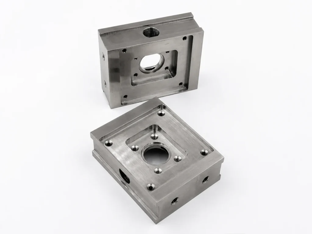
Five-Axis Machined 304 Stainless-Steel Component with Controlled Flatness
The same as-machined 304 stainless-steel component shown in two orientations after five-axis CNC milling for low-volume production.
Material
Stainless Steel 304
Machining Process
5-Axis CNC Milling
Surface Finish
As Machined
Production Type
Low-Volume Production
Critical Requirements
0.05 mm Flatness and Ra 1.6 μm Surface Roughness
Key Machining Challenge
This block-shaped component combines recessed pockets, a central bore, counterbores, threaded holes and features on multiple faces. The machining plan must maintain 0.05 mm flatness on the specified plane and achieve Ra 1.6 μm on the controlled surface while preserving the dimensional relationships between the surrounding features.
Machining Approach
Five-axis CNC milling provides access to the pockets, bores and side features with fewer repositioning steps. The workholding and machining sequence were planned around the controlled flatness and surface-finish requirements while maintaining consistent feature relationships.
Inspection
A CMM was used to verify the specified flatness, controlled dimensions and positional relationships. Threaded features were checked with thread gauges, and the Ra 1.6 μm requirement was verified using a surface roughness tester.
Why Work with Samshion for CNC Milling?
Reliable CNC milling depends on more than machine capacity. We control the files, approvals and production scope used for each order so that machining, finishing and inspection follow the same confirmed requirements.
Quotation Based on Current Files
The quotation is prepared from the current CAD model, controlled drawing and confirmed material, quantity, finish and inspection requirements. Missing or conflicting information is clarified before release.
No Unapproved Specification Changes
Questions affecting manufacturability, cost or verification are returned for review. Controlled geometry, tolerances, materials and finishes are not changed without customer approval.
One Approved Scope Across Operations
Machining, deburring, approved secondary processes, inspection and documentation follow the same confirmed order requirements. Lead time and reporting scope are recorded in the quotation.
Current Revision Checked for Repeat Orders
Repeat production is checked against the latest drawing revision, material, quantity, finish and documentation requirements. Retained programs and tooling are released only after the current order has been reviewed.
CNC Milling from Prototype to Production
A CNC milling route can evolve as a project moves from validation to repeat production. Workholding, program controls, inspection frequency and documentation are reviewed for the approved quantity rather than carried forward unchanged from the prototype stage.
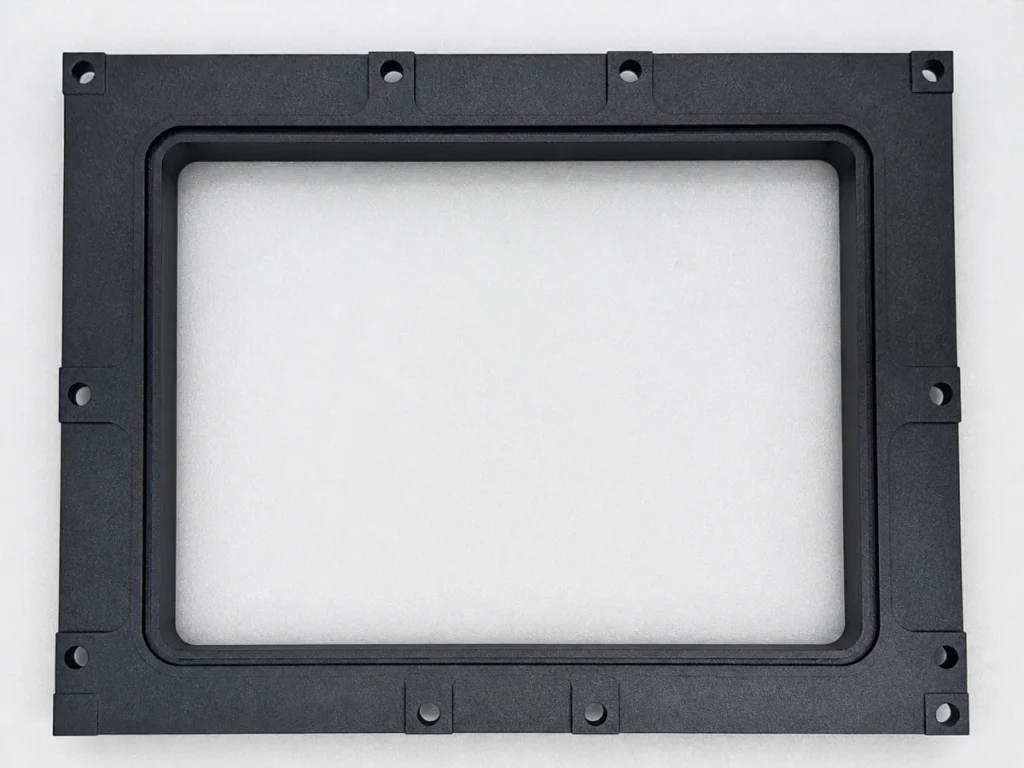
Prototype and Design Validation
Prototype parts can be machined in the intended engineering material to evaluate fit, assembly and function. Flexible workholding and timely engineering feedback are prioritized while critical drawing requirements remain controlled.
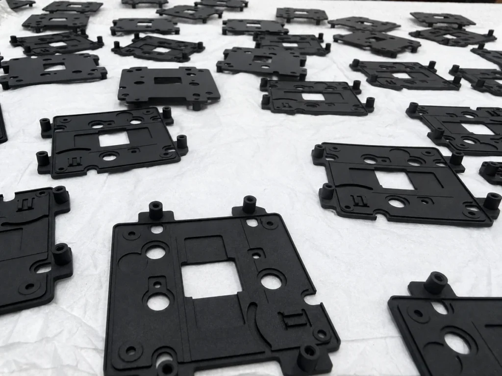
Bridge and Low-Volume Production
For bridge and low-volume orders, the process is stabilized through documented programs, repeatable workholding and a defined inspection plan. This supports consistent batches without committing to dedicated high-volume tooling.
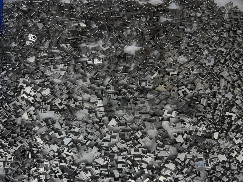
Repeat Production Batches
For recurring demand, controlled programs, workholding instructions and inspection plans support consistent batch release. Material availability, production capacity and required delivery dates are reviewed for each order.
CNC Milling Materials
Material selection affects machinability, dimensional stability, surface finish, tool wear and total part cost. We machine common metals and engineering plastics and review the specified grade, temper or condition, stock form, quantity and certification requirements during quotation. The examples below are not an exhaustive material list.
Material Verification, Certificates and Traceability
When required by the project, incoming material can be checked against purchasing documents and material certificates. XRF alloy verification is available for applicable metallic materials. Material certificates, RoHS and REACH documentation can also be supplied on request. Tell us the required documentation and traceability scope during quotation.
Aluminum Alloys
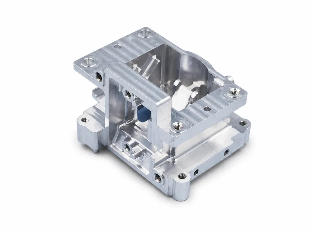
Common Grades: 6061-T6, 7075-T6, 7050, 2024, 2A12, 6082, 5083, 5052, 6063 and MIC6
Aluminum is commonly selected for housings, frames, brackets and multi-face components because it combines good machinability with relatively low weight. We review the grade and temper, stock flatness, wall thickness, finishing allowance and distortion risk after material removal.
Stainless Steel
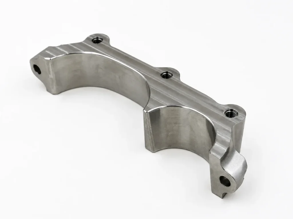
Common Grades: 303, 304, 316/316L, 410, 420 and 17-4PH
Stainless steel is used for components requiring corrosion resistance, mechanical strength and durable functional surfaces. Machining planning considers work hardening, heat generation, tool access, thin sections and the required surface condition.
Carbon and Tool Steel
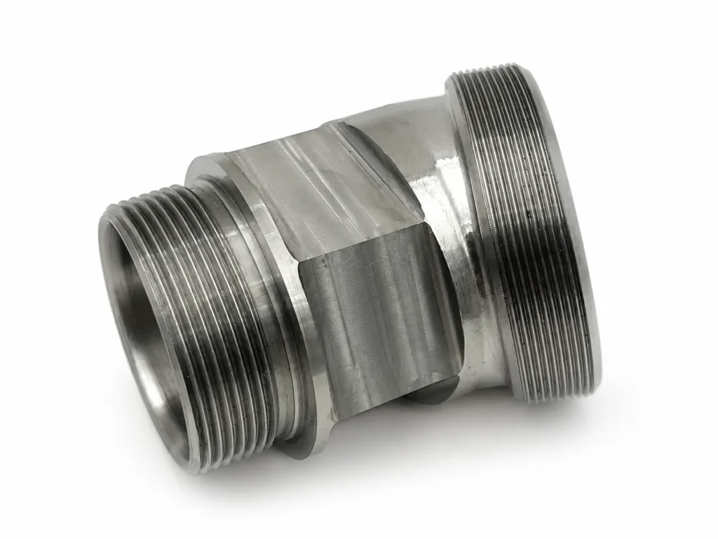
Common Grades: 1018, 1045, 4140, 4340, A2, D2, O1 and S7
Carbon and tool steels are selected where higher strength, hardness or wear resistance is required. Material condition, heat-treatment requirements, machining allowance, dimensional change and the inspection sequence are reviewed before production.
Copper and Brass
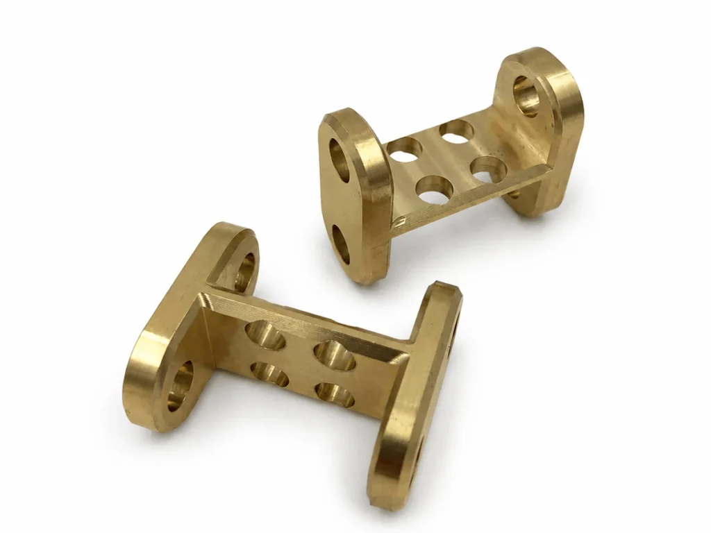
Common Grades: C101, C110, C145, C172, C260 and C360
Copper and brass may be selected for electrical, thermal or mechanical requirements. Machining planning considers alloy condition, burr control, thin-wall stiffness, heat transfer, surface protection and the relationships between holes and mating features.
Titanium
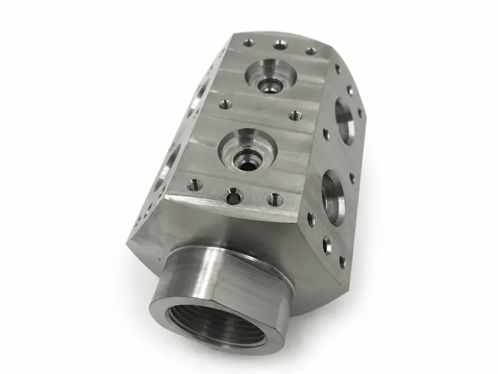
Common Grades: Grade 2 and Grade 5 (Ti-6Al-4V)
Titanium machining requires careful control of heat, cutting-tool engagement, tool access and workholding stability. The machining route, inspection scope and lead-time basis are confirmed after the specified grade, geometry and quantity are reviewed.
Engineering Plastics
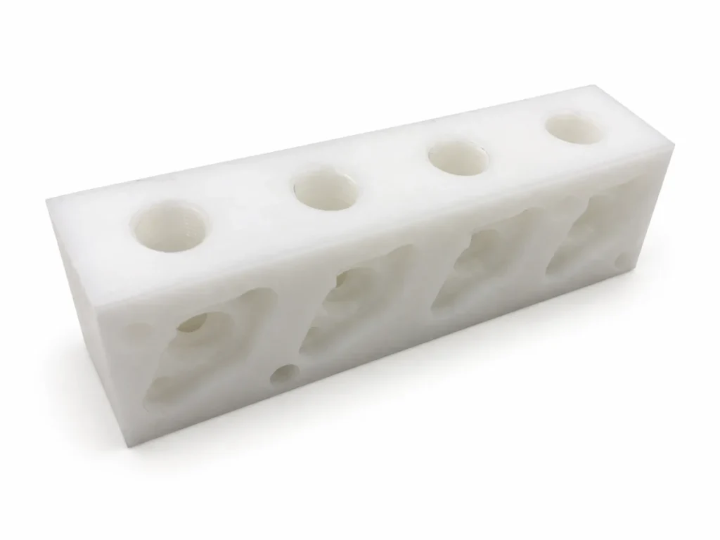
Common Grades: POM/Acetal, PEEK, Nylon, PTFE, PC, ABS and UHMW-PE
Engineering plastics can be CNC milled for housings, guides, blocks, fixtures and functional prototypes. The machining plan considers clamping pressure, heat generation, material movement, wall thickness, burr control and dimensional stability after the part is released.
Looking for another grade or stock form? View our complete CNC machining materials guide or upload your drawing for review.
Surface Finishes for CNC Milled Parts
Surface finishing can change the appearance, corrosion resistance, wear behavior and surface texture of a CNC-milled part. Finish selection should be reviewed together with the material, geometry, dimensional tolerances, masking areas and functional surfaces defined on the drawing.
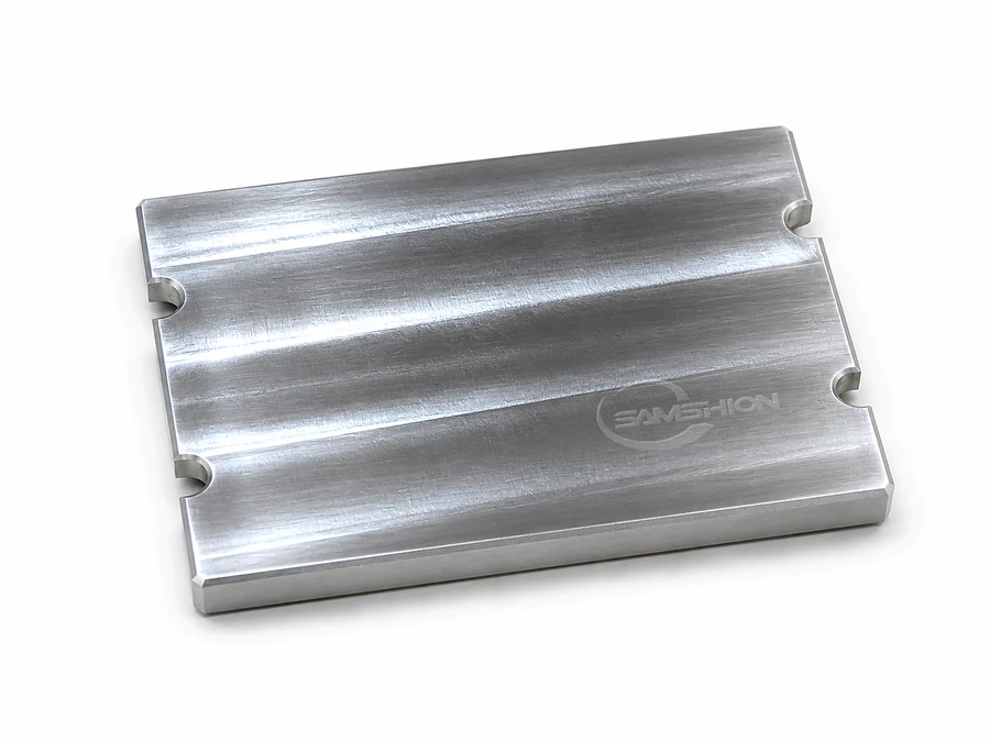
As Machined
Parts are deburred and cleaned after machining, with normal CNC tool marks remaining on the surface. This is generally the most economical option when no secondary coating or cosmetic finish is required. Any specified roughness or appearance limit should still be identified on the drawing.
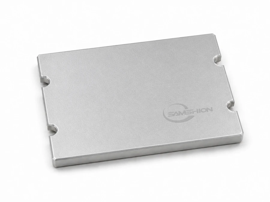
Bead Blasting
Bead blasting creates a uniform matte texture and reduces the visual contrast of light machining marks, although deeper marks may remain. The blasting media and target appearance should be confirmed before processing. Sealing faces, threads and precision bores may require protection.
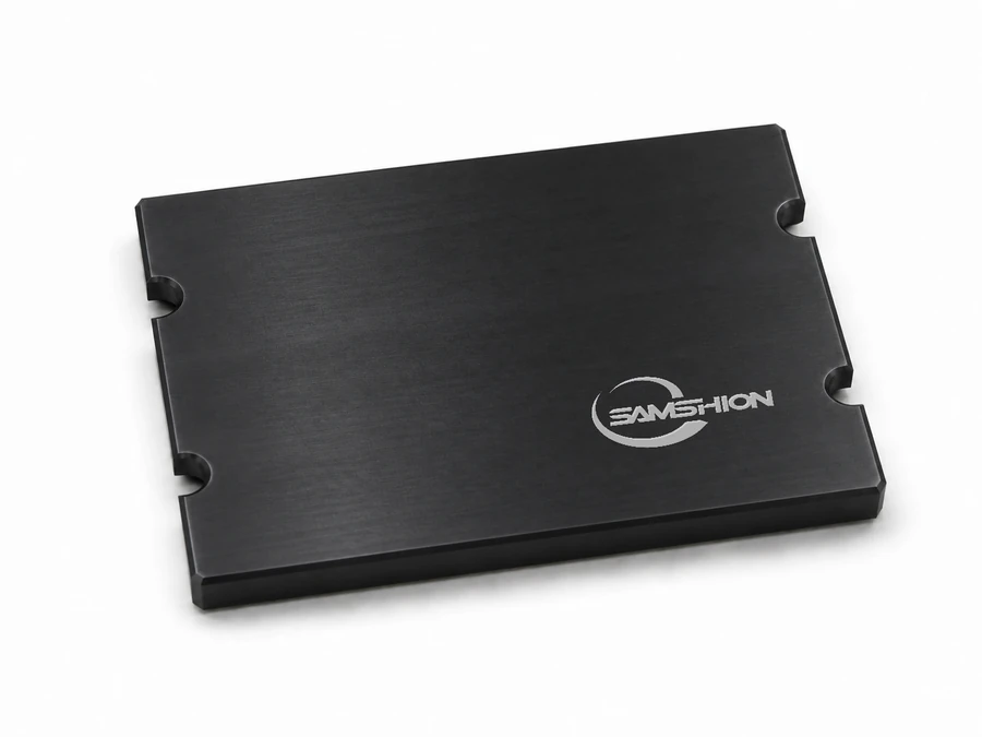
Anodizing
Anodizing is used on aluminum parts to improve corrosion resistance and provide decorative or wear-resistant surfaces. The anodizing type, color, coating thickness, electrical-contact areas and masking requirements should be defined because coating growth can affect threads, bores and fitted features.
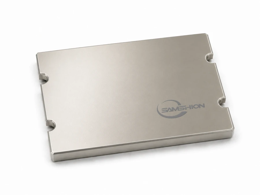
Electroless Nickel Plating
Electroless nickel plating deposits a relatively uniform metallic layer that can improve corrosion and wear resistance. Because the plating adds thickness, critical bores, threads, fits, sealing surfaces and masked areas should be reviewed against the drawing before the finishing route is confirmed.
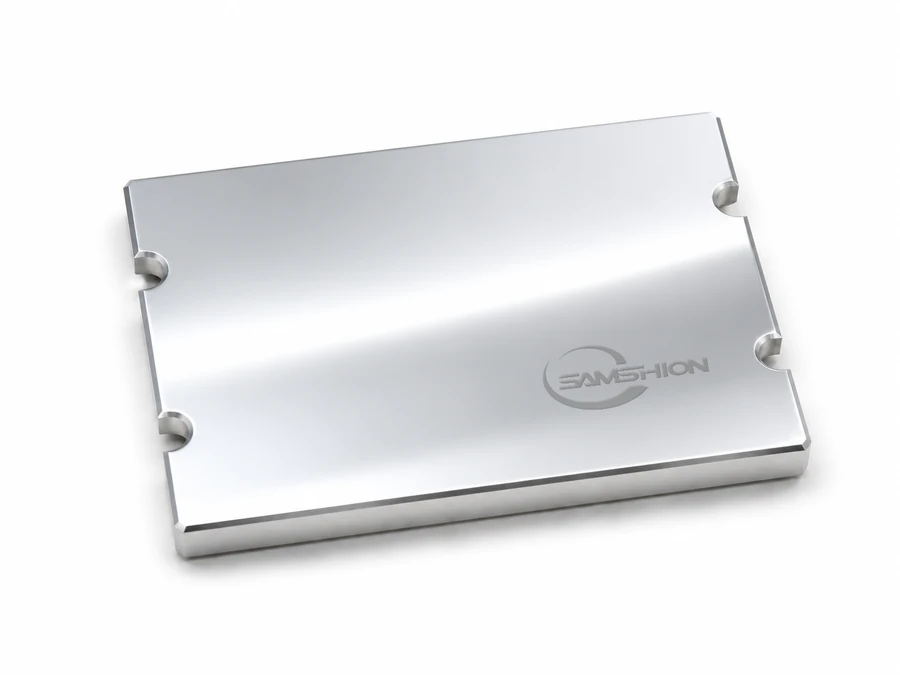
Polishing and Brushing
Polishing creates a smoother, more reflective surface, while brushing produces a controlled directional texture. The achievable appearance depends on the material, geometry and starting surface. When cosmetic consistency matters, specify the visible faces, grain direction, finish level or an approved reference sample.
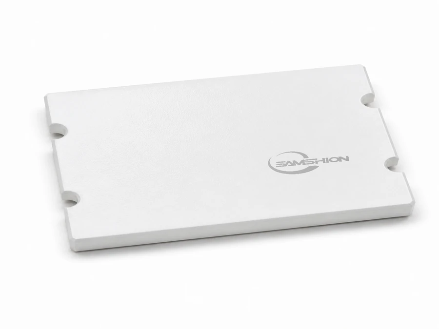
Powder Coating
Powder coating forms a durable colored polymer layer on compatible metal parts and is available in different textures and gloss levels. Threads, bores, grounding points, sealing faces and tight-clearance features normally require masking or dimensional allowance because the coating is comparatively thick.
CNC Milling Tolerances and Drawing Requirements
CNC milling tolerances are assigned according to feature function rather than applying one value to the entire part. The approved drawing and quotation define the applicable general tolerance, individually controlled dimensions, GD&T, surface condition and inspection scope.
What to Define on the 2D Drawing
For tolerance-sensitive parts, provide a controlled 2D drawing that identifies:
- Part number, drawing revision and units
- The applicable general tolerance standard and class
- Individually toleranced and critical-to-quality dimensions
- Datum references and geometric tolerances
- Surface texture requirements
- Thread standard, size, tolerance class and depth
- Material grade, condition, heat treatment and certification requirements
- Coating thickness and masking requirements
- Inspection scope, sampling quantity and report format
Before programming begins, we confirm the approved drawing revision, material requirements, surface finish, critical features and required documents.
Selected critical features may be supported to ±0.01 mm when geometry, material stability, workholding, finishing and inspection access allow. Requirements tighter than the selected general tolerance class are reviewed feature by feature.
ISO 2768-1:1989 General Linear Tolerances, Excluding Broken Edges
When ISO 2768-1:1989 and a tolerance class are specified on the drawing, the following permissible deviations apply to linear dimensions that do not already have an individual tolerance.
Values are in millimeters. Each value is a symmetric permissible deviation.
0.5 up to 3
±0.05
±0.1
±0.2
N/A
Over 3 up to 6
±0.05
±0.1
±0.3
±0.5
Over 6 up to 30
±0.1
±0.2
±0.5
±1
Over 30 up to 120
±0.15
±0.3
±0.8
±1.5
Over 120 up to 400
±0.2
±0.5
±1.2
±2.5
Over 400 up to 1000
±0.3
±0.8
±2
±4
Over 1000 up to 2000
±0.5
±1.2
±3
±6
Over 2000 up to 4000
N/A
±2
±4
±8
Review our CNC Machining Tolerance Guide for general-tolerance reference tables and more detailed drawing guidance.
Quality Control Process for CNC Milled Parts
Quality control for CNC-milled parts is planned from the approved drawing and quoted inspection scope. It includes pre-production review, internal first-off and in-process checks, final inspection, and release of the agreed records.
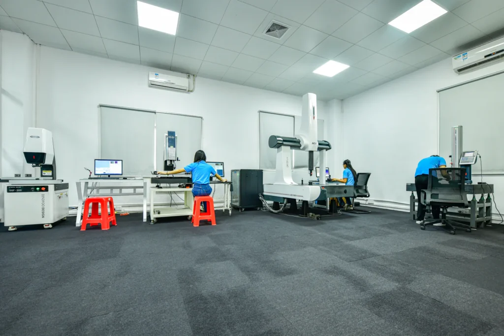
Inspection equipment is selected according to the feature geometry, tolerance and required measurement accuracy.
Learn more about our quality assurance and inspection process.
Before Machining: Inspection Planning
Before the program is released, we review the drawing revision, material grade and condition, critical characteristics, applicable datums, surface requirements and required documentation. Inspection methods and any customer approval hold points are confirmed during quotation.
During Production: Internal First-Off and In-Process Checks
Every order receives internal first-off and process-stability checks appropriate to the part and quantity. For multi-part orders, selected characteristics are checked at planned stages and sampled during production according to the agreed inspection plan. These internal production checks are separate from a customer-facing FAI report, which is supplied only when included in the approved quotation.
Before Shipment: Final Inspection and Document Release
Finished parts are inspected against the approved drawing, surface requirements and agreed sampling plan. Dimensional reports, CMM reports, FAI documentation, material certificates or Certificates of Conformance are released with the order when included in the approved quotation.
CNC Milling Design Guidelines
The following guidelines help designers prepare CNC-milled parts for quotation and production. They are practical starting points rather than universal limits; final recommendations depend on part function, material and complete geometry.
Use the Largest Practical Internal Radius
Because end mills are round, vertical internal corners cannot be perfectly sharp. Use the largest radius the design permits and avoid matching it exactly to the intended cutter radius so the tool has room to move and finish the corner. If a sharp internal corner is functionally required, identify it for alternative process review.
Provide Access to Deep Pockets
Where function allows, increase the pocket opening, reduce its depth or provide access from another direction. For unavoidable deep and narrow cavities, identify the critical floors, walls, corner radii and surface requirements on the drawing.
Support Thin and Tall Walls
Use consistent wall thickness, add ribs or supports where function allows, and avoid abrupt transitions between thick and thin sections. Identify walls that must remain flexible or unsupported so the machining approach can be planned accordingly.
Specify Holes and Threads Completely
Use standard drill, reamer and tap sizes where possible. State the thread standard, nominal size, pitch, class, effective depth and whether the hole is through or blind. Identify any functional gauge requirements.
Identify Undercuts and Restricted Features
Define the undercut width, depth, radius and access direction. Standard feature dimensions can reduce special-tooling requirements, while hidden or restricted features may require another setup or an alternative manufacturing route.
Coordinate Engraving with the Final Finish
Specify the marking content, location, orientation, line width or depth, and whether engraving is required before or after finishing. Anodizing, plating or coating can reduce the visibility of shallow engraving, so cosmetic acceptance requirements should be agreed before production.
From Quote to Finished CNC-Milled Parts
Our CNC milling workflow connects file review, route selection, controlled production and final release. The exact machining setup and inspection scope are confirmed for each project.
Submit Project Files
Submit the current 3D CAD model and, where controlled dimensions or specifications apply, the latest 2D drawing. Include the material, quantity, finish, delivery and inspection requirements.
Review Manufacturability and Route
Engineering reviews manufacturability and selects the machining route, tooling, workholding and inspection approach. Questions affecting function, cost or schedule are returned for clarification.
Approve Quotation and Scope
The quotation records the approved file revision, material, quantity, finish, tolerance and inspection scope, documentation and lead time. Production begins after the technical and commercial requirements are approved.
Program, Set Up and Check First-Off
The approved revision is programmed and the selected setup is prepared and verified. Every order receives internal first-off and process-stability checks at the planned stage. A customer approval hold point or formal FAI applies only when included in the quotation.
Machine, Finish and Monitor
Parts are machined using controlled programs and setup instructions. In-process checks, deburring, cleaning and specified finishing are completed according to the approved requirements.
Inspect, Document and Ship
Final inspection is completed against the approved drawing and agreed sampling plan. Required reports and certificates are prepared before the parts are protected, packed and shipped by the agreed method.
CNC Milling FAQs
What files and project information are needed for a CNC milling quote?
Send the current 3D solid model, preferably in STEP format, and a controlled 2D drawing when dimensions, GD&T or notes define acceptance. Include the material grade and condition, quantity, finish, target delivery date, and any inspection or documentation requirements.
How quickly can I receive a quote and finished CNC-milled parts?
We normally provide a detailed quotation within 24 hours after receiving a complete RFQ package. Selected prototype projects may have production lead times starting from 3 business days. Shipping time is separate, and the confirmed schedule is stated in the quotation.
How do you choose between 3-, 4- and 5-axis CNC milling?
The route depends on feature access, setup requirements, datum relationships, tool-holder clearance and part geometry. Three-axis milling suits accessible prismatic features, while four- or five-axis machining may be selected for angled, multi-face or contoured geometry. The final route is confirmed after reviewing the actual files.
What factors have the greatest effect on CNC milling cost?
The main factors include material and stock size, part geometry, setup count, machining time, tool reach and wear, quantity, finishing, inspection scope and documentation. Providing the expected order quantity and repeat demand helps us evaluate the most practical production route.
Can selected dimensions be held to ±0.01 mm?
Selected critical linear dimensions may be quoted to ±0.01 mm when geometry, material stability, workholding, finishing and measurement capability allow. This value does not apply automatically to every dimension. General tolerances follow the approved drawing and our ISO 2768-mK convention where applicable.
What inspection is performed, and which quality documents are available?
Every order receives internal first-off and process-stability checks, followed by in-process and final inspection as appropriate to the part and quantity. Customer-facing dimensional reports, CMM reports, formal FAI documentation and material certificates are supplied when included in the approved quotation.
Can you support an NDA before I share CAD files and drawings?
Yes. An NDA can be reviewed before sensitive project files are shared. If your company uses its own NDA form, send it to us for review before uploading the complete design package.