
Laser Cutting Services for Custom Sheet Metal Parts
Produce flat blanks, brackets, panels, enclosures and precision profiles from sheet metal without dedicated profile tooling. SAMSHION supports prototypes, low-volume batches and repeat production with DFM feedback, nesting review, secondary fabrication and inspection planning based on your drawings.
- Steel, stainless steel, aluminum and approved copper alloys
- Complex 2D contours, holes, slots and perforated patterns
- Bending, hardware installation, welding and finishing available
- Inspection planned around critical drawing requirements
Custom Laser Cutting from Prototype to Repeat Production
Laser cutting converts digital geometry into accurate flat metal profiles by using a focused beam and controlled assist gas to separate material along a programmed path. Because the outline is created without a dedicated blanking die, the process is well suited to prototypes, design revisions, mixed part families and production orders that benefit from efficient sheet nesting.
Laser cutting is one stage within our broader sheet metal fabrication services. A complete part may continue through bending, tapping, hardware installation, welding, grinding, surface finishing and assembly. SAMSHION reviews the entire route before production so a clean laser-cut blank also works correctly in the forming and assembly stages that follow.
For the most accurate review, send the flat DXF or DWG together with a STEP model when the final part contains bends or assembled features. A 2D PDF drawing should identify material grade, thickness, critical dimensions, tolerances, edge requirements, finish, cosmetic surfaces and inspection notes.
Why Choose Samshion Rapid for Laser Cutting Services?
Engineering Review Before Cutting
We review open contours, duplicate lines, very small features, narrow webs, hole-to-edge distances, material, thickness and downstream bending requirements before releasing the file. Questions are resolved while changes are still inexpensive.
Process Planning Beyond the Flat Blank
The best cutting layout must also support forming, fastening, welding and finishing. Grain direction, bend orientation, cosmetic surfaces and coating thickness can affect how blanks should be nested and handled.
Flexible Quantities Without a Dedicated Profile Die
Digital cutting avoids the dedicated blanking tool required by conventional stamping. This reduces upfront tooling for prototypes and changing designs, although programming, setup, material and secondary operations still contribute to cost.
Inspection Based on Functional Requirements
Critical hole patterns, outer profiles, slot locations and overall dimensions are checked according to the drawing and process risk. Additional documentation can be defined during quotation.
What Is Fiber Laser Cutting?
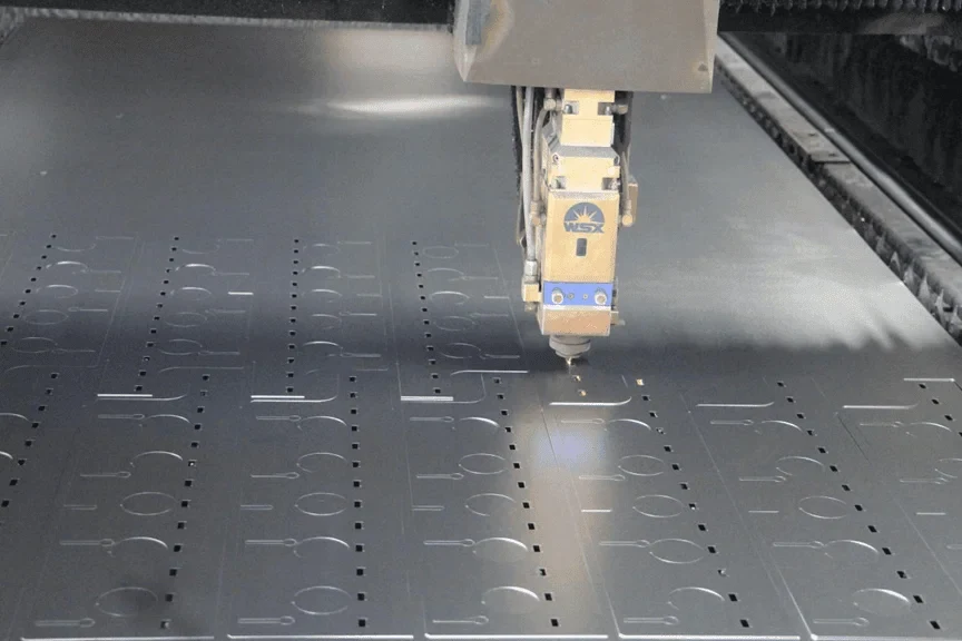
Fiber laser cutting uses a concentrated laser beam to heat a narrow path through metal while an assist gas clears molten material from the kerf. The machine follows a programmed 2D toolpath, allowing complex contours and repeated features to be produced directly from digital geometry.
The final edge depends on more than machine power. Material grade, thickness, surface condition, beam focus, gas type and pressure, nozzle condition, feature size, piercing strategy and cutting speed all influence taper, dross, oxidation and heat tint. A realistic quotation therefore evaluates the complete part rather than promising one universal edge condition or tolerance.
Fiber laser cutting is normally most valuable for metal sheet and plate. Non-metallic materials require different equipment, extraction and material-specific safety controls. SAMSHION should not advertise plastic, foam, wood or textile cutting on this page unless those processes are separately validated and available.
Our Laser Cutting Capabilities
How the Laser Cutting Process Works
File and Drawing Review
The engineer checks scale, units, closed profiles, duplicate lines, material, thickness, tolerances and the relationship between the flat blank and the final formed part.
CAM Preparation and Nesting
Nominal geometry is imported into the cutting software. The programmer applies process compensation and arranges parts to balance material yield, cut stability, heat distribution and part identification.
Setup and First-Off Cutting
Material and assist gas are confirmed, the sheet is loaded, and the first part or representative sample is cut. Critical features are checked before the full order continues.
Production Cutting
The machine follows the approved toolpath. Piercing, contour order and small-feature strategy are selected to control heat, movement and cut quality.
Deburring and Secondary Operations
Parts are separated from the sheet and inspected for sharp edges, dross or handling marks. Required deburring, bending, hardware, welding or finishing follows the agreed route.
Final Inspection and Packaging
Dimensions, quantity, visual condition and documentation are checked before parts are protected for shipment.
Metals for Laser Cutting
Material grade and thickness affect absorption, cutting speed, edge condition, gas choice, thermal movement and downstream forming. Use our manufacturing materials guide for broader comparison, then identify the exact alloy, temper or condition on the drawing.
Carbon and Mild Steel
Carbon steel is widely used for structural brackets, frames, base plates, guards and general enclosures. Oxygen may improve cutting speed on suitable thicker steel, while nitrogen may be chosen when an oxide-free edge is required. The selected gas and post-processing route should match welding and coating needs.
Stainless Steel
Stainless steel is used for corrosion-resistant panels, equipment parts, food-contact hardware and clean-looking enclosures. Nitrogen-assisted cutting can help avoid an oxidized edge, but cut quality still depends on thickness, grade, parameters and feature size.
Aluminum
Aluminum provides low mass and corrosion resistance for electronics, transportation and equipment components. Alloy and temper affect cutting and bending behavior. When the blank will be formed, the material and grain direction should be reviewed together with bend radii and cosmetic requirements.
Copper and Brass - Confirm Capability
Reflective copper alloys require suitable fiber-laser equipment, parameters and safety controls. Publish copper or brass cutting only after production confirms approved alloys and thickness ranges. These materials are common for busbars, electrical contacts, shields and decorative components.
Specialty Metals - Engineering Review
Spring steels, coated sheet and other specialty alloys may require trial cutting or a project-specific process review. Surface coatings, protective films and heat sensitivity should be disclosed before quotation.
Common Laser-Cut Part Types
- Flat brackets, mounting plates and reinforcement plates
- Electronics faceplates, control panels and equipment covers
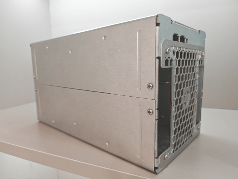
- Enclosure blanks and chassis components prepared for bending
- Ventilation grilles, perforated panels and protective guards
- Shims, spacers, gaskets and thin precision profiles
- Busbars, terminals and conductive parts in approved copper alloys
- 19. Part families or kits nested from common material and thickness
From Quote to Laser-Cut Parts
Upload Files
Send DXF or DWG for flat contours, STEP for formed parts, and a PDF drawing for tolerances, finish and inspection notes.
DFM Review
We check geometry, material, thickness, small features, nesting, forming and secondary operations.
Quote and Route Confirmation
The quotation defines material, quantity, cutting scope, secondary work, finishing, inspection and delivery assumptions.
Programming and First-Off
CAM toolpaths and nesting are prepared, then a first part or representative sample is checked.
Production and Secondary Fabrication
Approved parts are cut and continue through deburring, bending, hardware, welding or finishing as required.
Final Check and Shipment
Parts are inspected, protected and shipped with the documentation included in the agreed scope.
Quality Control for Laser-Cut Parts
Our quality assurance and inspection approach is based on the drawing, manufacturing risk and agreed documentation scope. Inspection must distinguish the laser-cut blank from dimensions created later by bending, machining, welding or coating.

File and Material Verification
Before cutting, confirm revision, units, scale, material grade, thickness, quantity and surface condition. Protective film and material certificates should be addressed during quotation when required.
First-Off Dimensional Check
Check the first part or representative sample for outer profile, critical holes, slots, overall dimensions and features that influence downstream forming or assembly.
In-Process and Edge Inspection
Monitor critical dimensions and look for excessive dross, incomplete cuts, heat effects, movement or handling damage. Sampling frequency should follow process stability and project requirements.
Final Inspection and Documentation
Verify quantity, selected dimensions, visual condition, deburring, secondary operations and packaging. Dimensional reports, material certificates or other records should be agreed before production.
Secondary Fabrication after Laser Cutting
Flat blanks can continue directly to our CNC bending services when the final component includes flanges, channels or enclosure geometry. Bend allowance, grain direction, inside radius and hole-to-bend distance should be reviewed before cutting.
Additional operations can include deburring, countersinking, tapping, self-clinching hardware, TIG or MIG welding, grinding and assembly. For high-volume repeated profiles that justify dedicated tooling, metal stamping services may provide a lower unit cost than laser cutting. The decision should consider annual quantity, geometry stability, tooling cost and secondary operations.
Post-processing can include powder coating, anodizing, passivation, plating, brushing or other approved treatments. Review our surface finishing options and state coating thickness, masking, color, texture, cosmetic class and any dimensions that apply after finishing.
Laser Cutting Design Guidelines
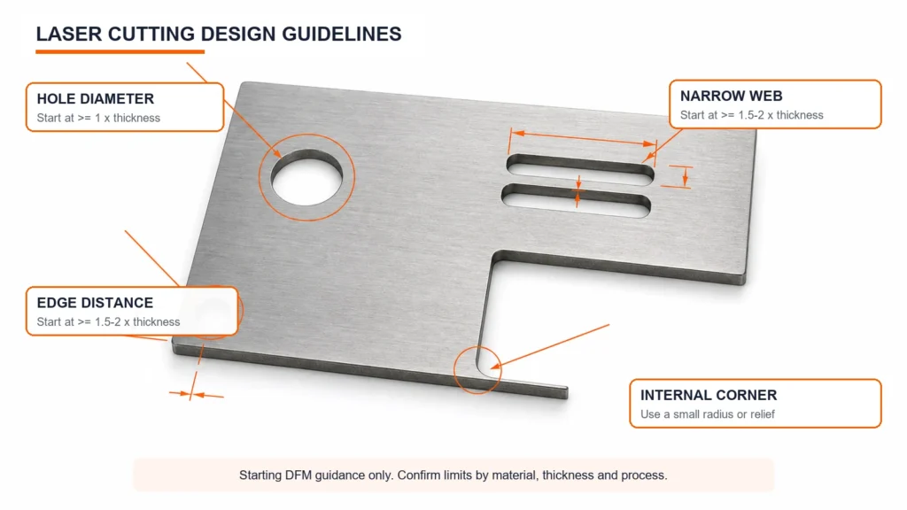
The following values are starting points for DFM review, not universal acceptance limits. Material, thickness, gas, machine condition, feature purpose and downstream forming can change what is practical.
Provide Clean Nominal Geometry
Submit one closed contour for each cut edge. Remove duplicate lines, construction geometry, filled areas and overlapping profiles. Let the manufacturing CAM system apply kerf compensation; do not offset the customer DXF unless the supplier specifically requests it.
Identify Material and Thickness
State the exact grade, temper or condition and nominal thickness. A file named only ‘steel bracket’ does not provide enough information for cutting, bending or finishing review.
Use Practical Hole Sizes
As an initial rule, keep round-hole diameter at least near the material thickness. Smaller holes may be possible on some thin materials, but edge quality, taper and breakthrough should be confirmed during DFM.
Protect Narrow Webs and Edge Distance
Very narrow ribs or features close to an outer edge can accumulate heat or move after cutting. A starting clearance of approximately 1.5 to 2 times material thickness is often easier to manufacture, but the final requirement depends on geometry and material.
Use Small Internal Radii Instead of Perfect Sharp Corners
A laser path cannot create a mathematically perfect internal corner. Add a small radius or an intentional relief where a mating square feature requires clearance.
Show Bend Lines Separately
For formed parts, supply a STEP model and mark bend information in the drawing. Do not place bend lines on the same DXF layer as cut contours unless the quotation instructions specifically request that convention.
Limit Tolerances to Functional Features
Tighter limits can reduce cutting speed, increase inspection and require secondary machining or reaming. Apply them only to hole patterns, profiles or interfaces that control function.
Clarify Edge Break and Cosmetic Surfaces
Identify visible surfaces, grain direction, protective-film requirements and whether edges must be broken. This helps prevent handling marks and unexpected finish changes.
Laser Cutting FAQs
What files should I send for a laser cutting quote?
Send a DXF or DWG for the flat profile. If the part will be bent or assembled, also send a STEP model. Use a 2D PDF drawing to define material, thickness, tolerances, finish, cosmetic surfaces, edge requirements and inspection notes.
Which metals can SAMSHION laser cut?
The primary materials are carbon steel, stainless steel and aluminum. Selected copper alloys or specialty metals require confirmation of grade, thickness and machine suitability before quotation.
What tolerance can laser cutting achieve?
Tolerance depends on material, thickness, feature size, thermal behavior, gas, machine condition and measurement method. Send the drawing so critical features can be reviewed individually instead of relying on one universal tolerance claim.
Can laser-cut edges be completely burr-free?
Laser cutting can produce clean edges, but dross, heat tint or a sharp edge may remain depending on the process. If the part requires safe handling, sealing or cosmetic edges, state the requirement so deburring or edge finishing can be included.
What is the smallest hole I can use?
A hole diameter near or above the sheet thickness is a useful starting point. Smaller holes may be possible in selected thin materials, but DFM review is required because cut quality and taper can change.
Does laser cutting require tooling?
It does not require a dedicated profile die, which makes design changes and low-volume orders more flexible. Programming, setup, nesting, material and any special fixtures or secondary operations still affect price.
Can you bend and finish the parts after cutting?
Yes, when included in the agreed manufacturing route. Services can include deburring, CNC bending, hardware installation, welding, powder coating, anodizing, plating and other approved finishes.
Should I add kerf compensation to my DXF?
Normally, submit nominal finished geometry and allow the manufacturing CAM system to apply process compensation. Do not manually offset the file unless SAMSHION specifically requests it for the project.
How can I reduce laser cutting cost?
Use common material and thickness, avoid unnecessary tight tolerances, combine compatible part numbers for nesting, reduce excessive piercing, keep small features practical and provide clear quantity forecasts.
Can laser cutting support both prototypes and repeat production?
Yes. Digital cutting is suitable for prototypes and changing designs, and controlled nesting and inspection can support repeat orders. Higher stable volumes should also be reviewed against punching or stamping when dedicated tooling may reduce unit cost.