
Custom CNC Machining Services for Prototypes and Production Parts
Turn CAD models and engineering drawings into custom metal and plastic parts with a process route matched to geometry, material, tolerance, quantity and end use. SAMSHION supports CNC milling, turning, multi-axis machining and complementary processes for prototypes, bridge builds and repeat production.
- No MOQ, starting from one part
- Feature tolerances down to ±0.01 mm after drawing review
- As-machined and multiple surface finishing options
- All uploads are secure and confidential.
- Quotes within 24 hours
- Selected prototypes from 3 days
- ISO 9001 certified
Choose the Right CNC Machining Process
Start with the part’s dominant geometry. Components defined mainly by flat faces, pockets and features on multiple orientations usually begin with milling, while parts built around a central rotational axis usually begin with turning. When both feature groups are important, we can plan a combined machining route.
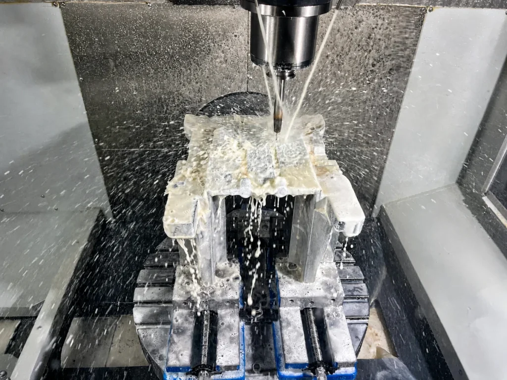
Custom CNC Milling Services
CNC milling is suited to plates, housings, pockets, multi-sided features and complex surfaces. We use 3-axis, 4-axis and 5-axis machining according to feature access and setup requirements.
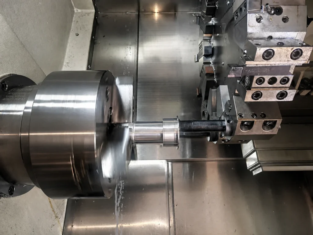
Custom CNC Turning Services
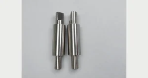
CNC turning is suited to shafts, sleeves, flanges, precision bores and threaded rotational parts. For components combining turned and milled features, mill-turn machining can reduce setup transfers.
CNC Machining Capabilities at a Glance
Our current equipment covers multi-axis CNC milling, CNC turning and C-axis live-tool machining. The following figures provide an initial view of the available machine configurations and working capacities.
3-axis, 4-axis, indexed 3+2 and simultaneous 5-axis CNC milling, CNC turning, C-axis live-tool and mill-turn machining, EDM and wire EDM
Up to Ø1,000 mm
CNC turning centers, including selected machines with C-axis control and live tooling
Up to Ø350 mm
Up to 1,000 mm
Machine travel, rotary-table diameter and turning limits describe individual equipment capacities rather than a guaranteed finished-part envelope. Usable dimensions depend on workholding, tool reach, rotary clearance, feature orientation and the required machining sequence.
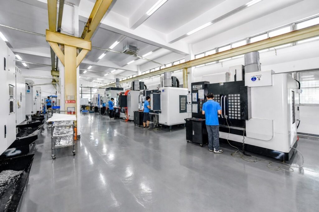
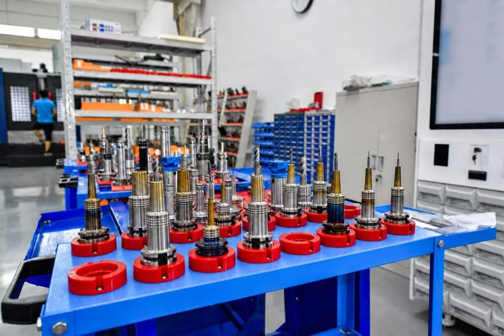
Inside the SAMSHION CNC Workshop
The photographs below show our actual CNC machining environment, production equipment, operators and tooling preparation.
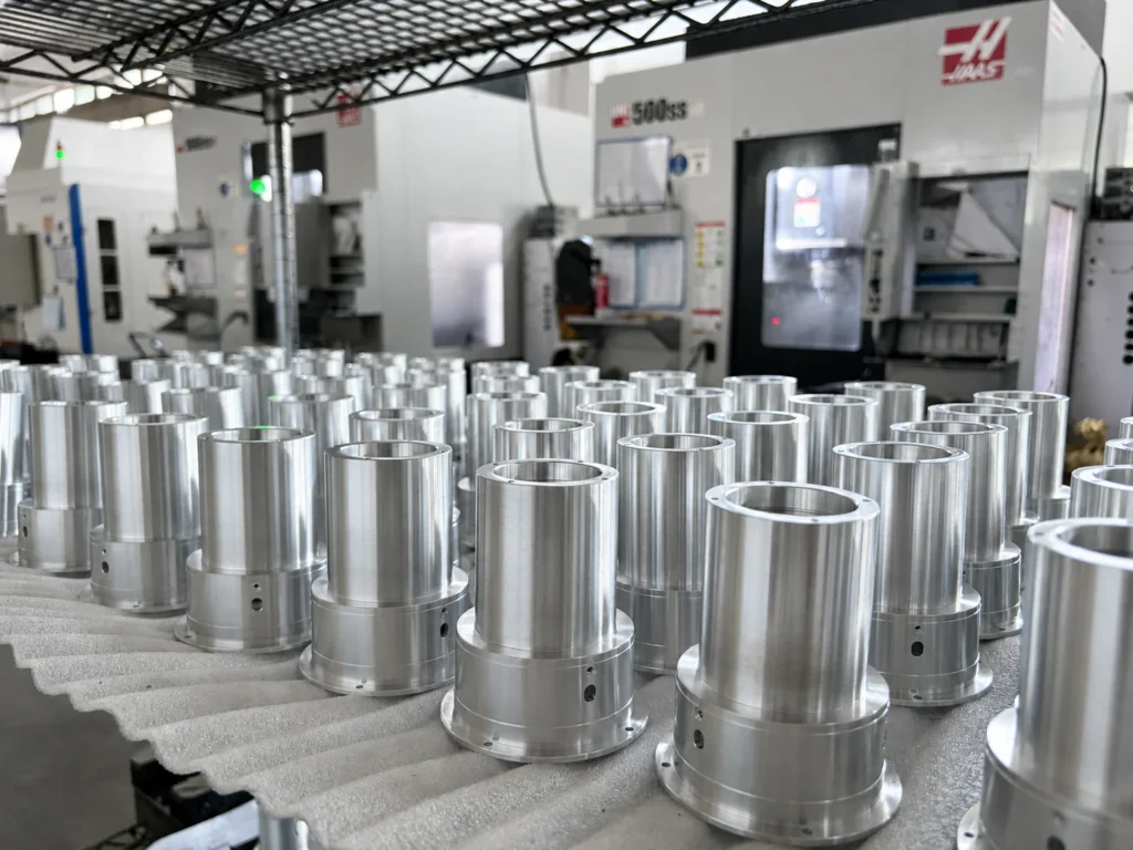
CNC Machining Workshop Overview
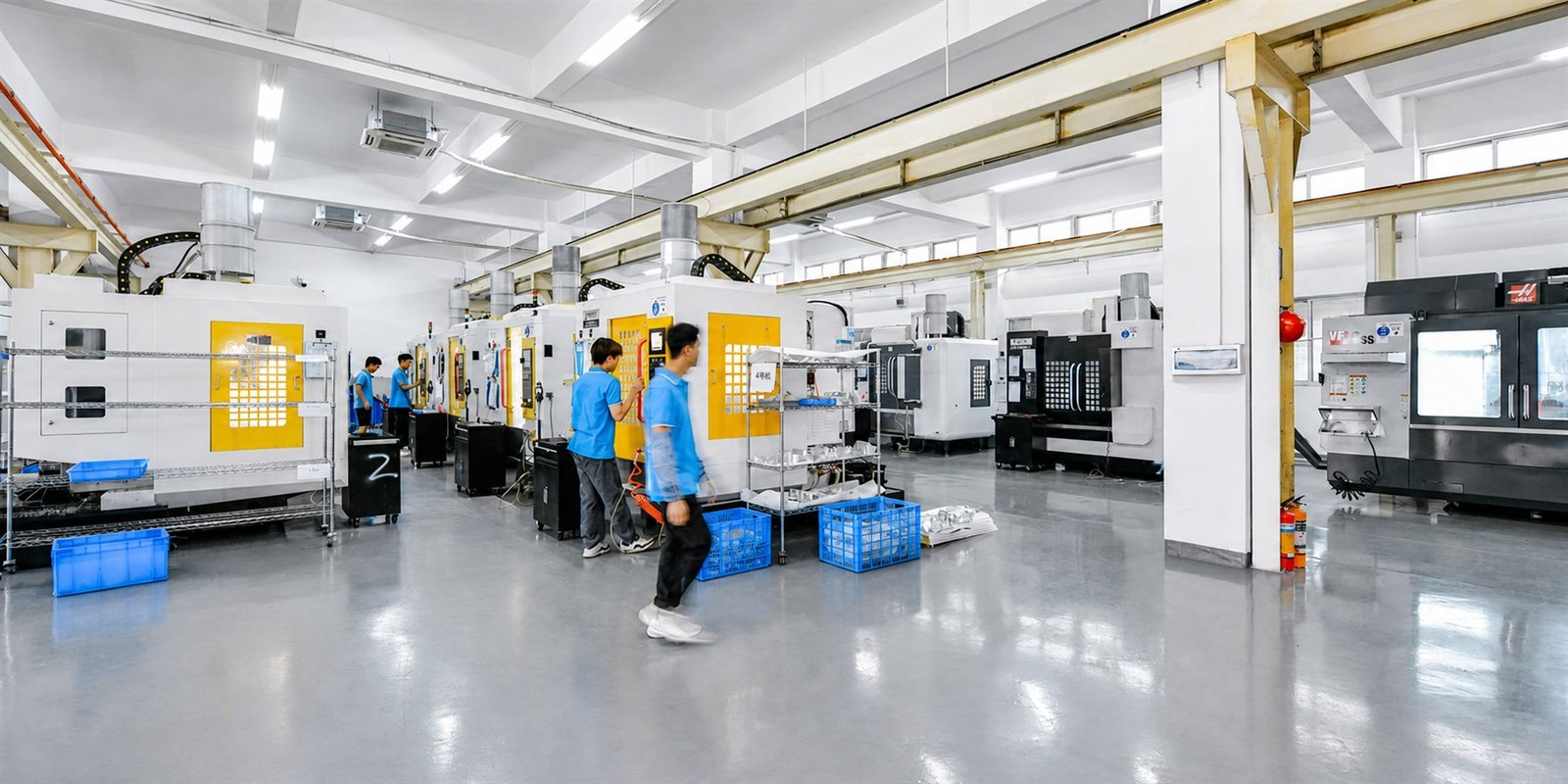
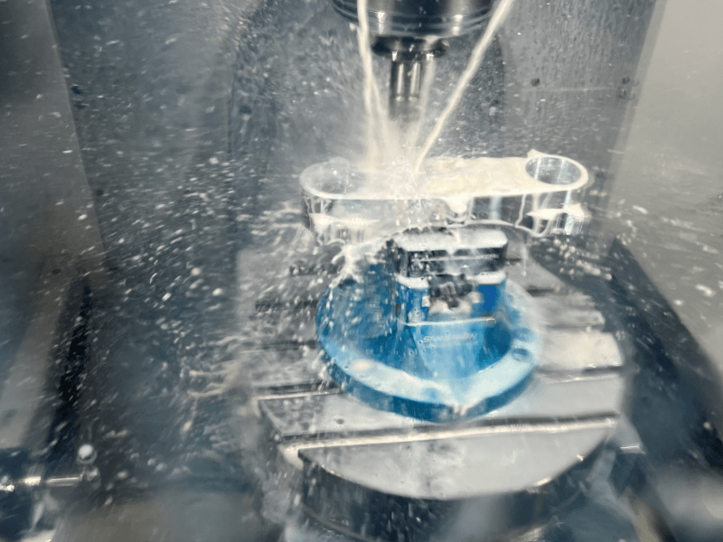
Production Equipment in Operation
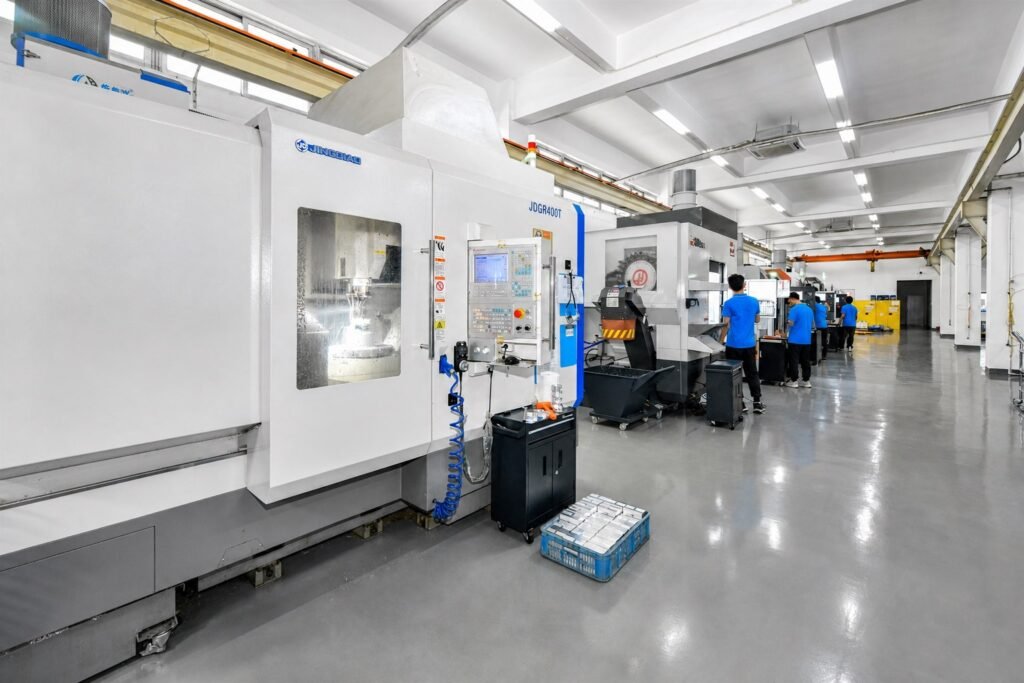
Day-to-Day CNC Production
Tooling Preparation
Why Choose SAMSHION for Custom CNC Machining?
Customers choose SAMSHION when a project requires more than machine time. We connect manufacturing review, controlled prototype-to-production transfer and drawing-based verification within one managed CNC machining project.
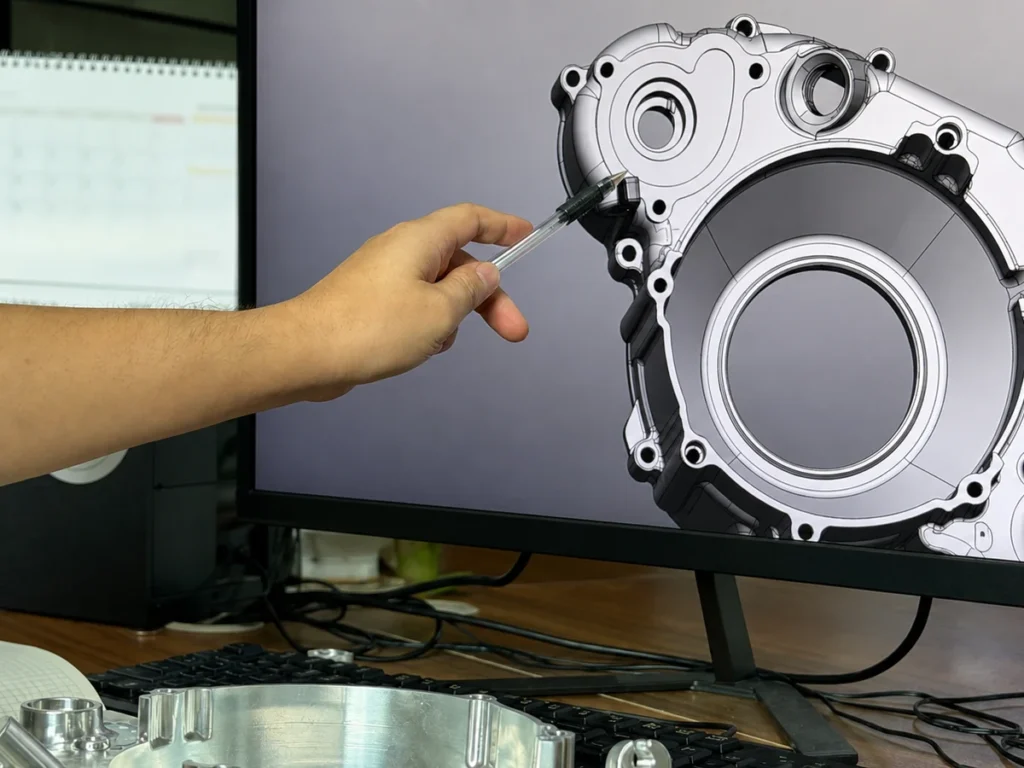
Manufacturing Review Before Cutting
Potential issues such as restricted tool access, unstable walls, deep internal features, unclear datums or coating-sensitive fits are identified before material is cut. Practical alternatives that may reduce risk or unnecessary cost are discussed with you before production.
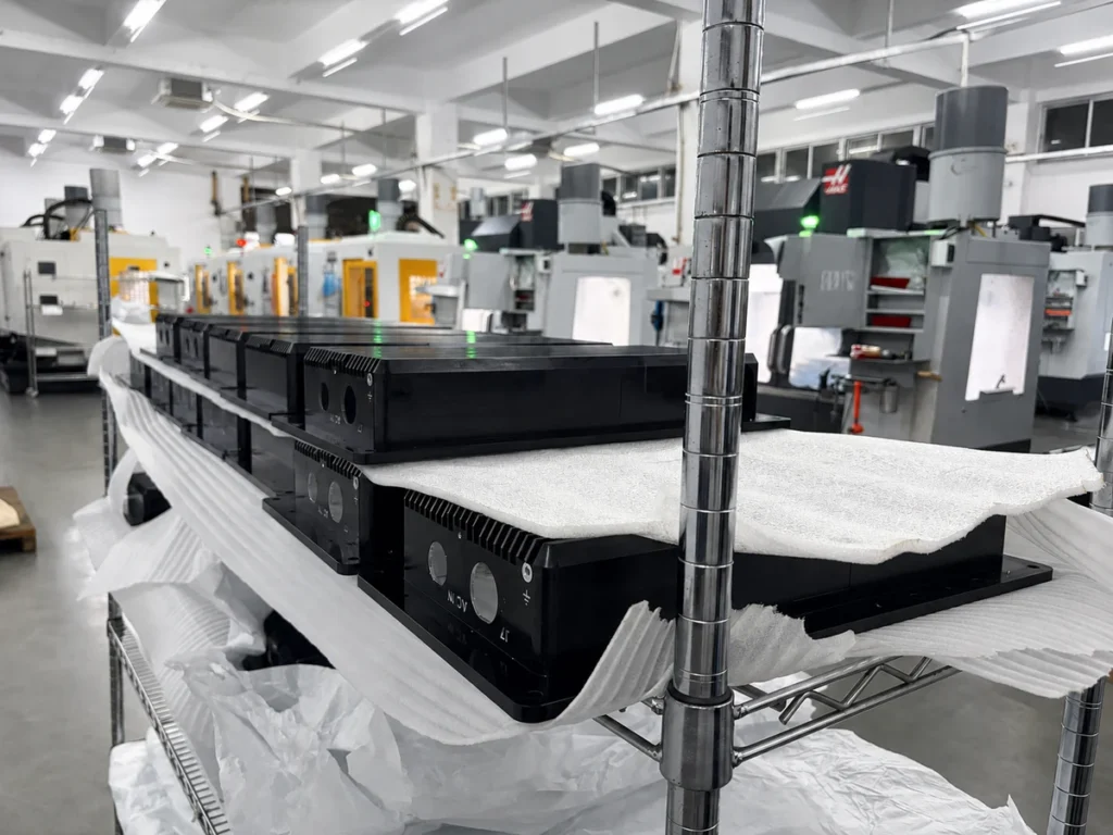
Coordinated Multi-Process Manufacturing
Projects combining milling, turning, C-axis live tooling, EDM or surface finishing can be managed under one manufacturing plan. Process sequence, datum transfers and inspection checkpoints are coordinated across the required operations.
Verification Matched to the Drawing
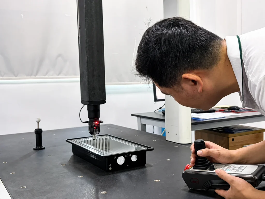
Critical dimensions and geometric relationships are assigned suitable inspection methods, including micrometers, gauges, height gauges and CMM where applicable. Formal reports and certificates are supplied when included in the quotation.
Real CNC Machining Project Examples
These projects show how different part geometries were matched to 3-axis, multi-axis, turning or combined machining routes. Each example focuses on a specific manufacturing challenge, the selected process and the critical features verified before delivery.
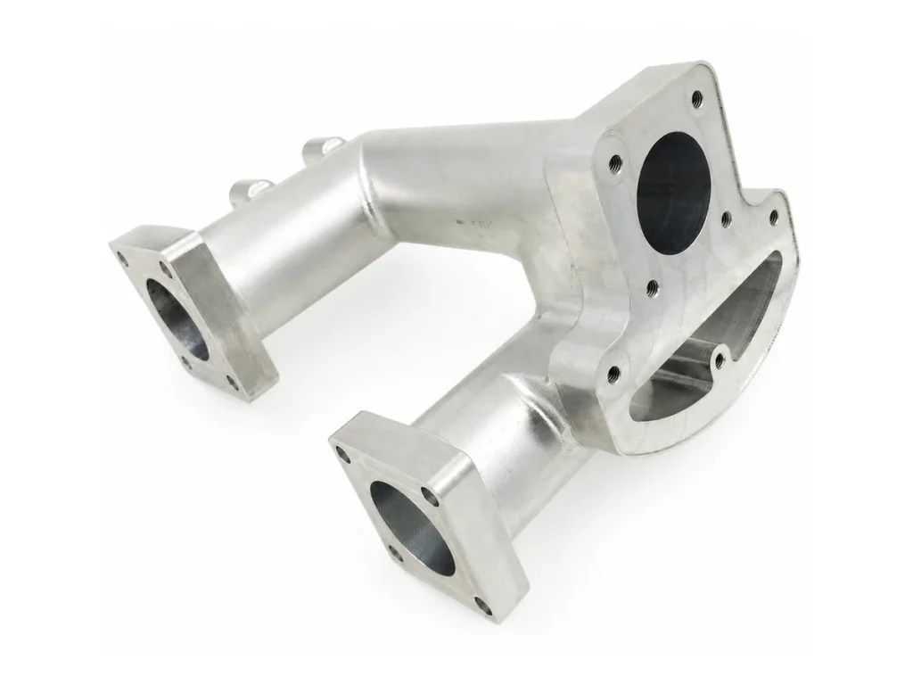
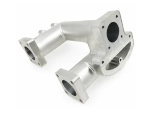
Automotive 5-Axis CNC-Machined 6061-T6 Aluminum Manifold
This automotive prototype manifold was machined as one integral component from 6061-T6 aluminum. Its approximate overall size is 250 × 200 × 200 mm. The part combines multiple mounting interfaces, deep intersecting passages, locating bores and threaded features that require machining access from several directions.
Project Information
- Material: 6061-T6 aluminum
- Approximate Size: 250 × 200 × 200 mm
- Manufacturing Process: 5-axis CNC machining
- Production Type: Single prototype
- Surface Condition: As-machined
- Typical Application: Automotive systems
Manufacturing Challenges
- Deep intersecting holes required careful control of tool reach, drilling direction and chip evacuation.
- The assembly sealing faces required a controlled low-roughness finish to support reliable sealing.
- Locating-hole positions required high accuracy, while the locating-bore diameters were specified with an H7 tolerance.
Our Manufacturing Approach
- 5-axis orientation provided access to angled interfaces, deep passages and features located in different directions.
- Process planning focused on the functional datums, sealing interfaces and positional relationships between locating features.
- CMM inspection was used to verify feature positions and interface relationships. Bore gauges and thread gauges were used to inspect precision holes and threaded features.
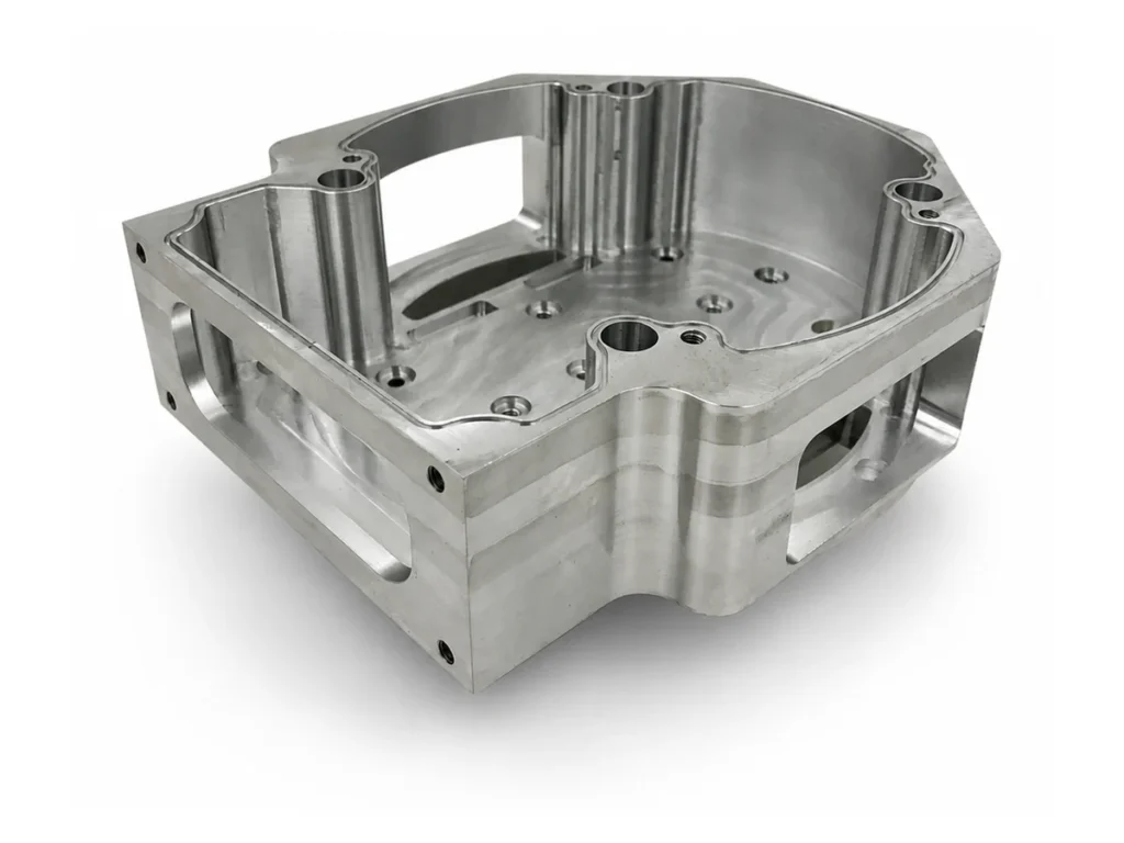
5-Axis CNC-Machined 6061-T6 Thin-Wall Aluminum Housing
This single prototype housing was machined as one integral component from 6061-T6 aluminum using 5-axis CNC machining. The part combines thin walls, an open internal cavity, precision locating holes, threaded features and multiple functional interfaces.
Project Information
- Material: 6061-T6 aluminum
- Manufacturing Process: 5-axis CNC machining
- Production Type: Single prototype
- Surface Condition: As-machined
- Inspection Methods: CMM, bore gauges and thread gauges
Manufacturing Challenges
- Control thin-wall deformation during workholding, rough machining and finish machining.
- Maintain the position of locating holes and the drawing-defined GD&T relationships relative to the functional datums.
- Achieve the specified surface roughness and flatness on the sealing and assembly interfaces.
- Provide sufficient tool access to the internal cavity, side features, holes and threaded features.
Our Manufacturing Approach
- Use 5-axis machining to access the internal cavity, side features, locating holes and functional faces with fewer unnecessary setup transfers.
- Plan the roughing, semi-finishing and finishing sequence to manage changing wall stiffness and reduce machining deformation.
- Define functional datums from the approved drawing before programming and inspection planning.
- Apply dedicated finishing passes to the sealing and assembly faces to control surface roughness and flatness.
- Use CMM inspection to verify sealing-face flatness, locating-hole position and drawing-defined GD&T requirements.
- Use bore gauges and thread gauges to verify specified hole and thread features.
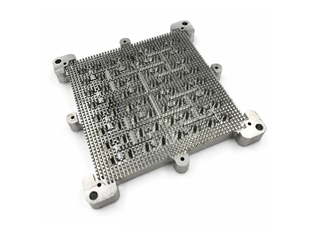
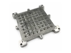
High-Density 7075-T6 Aluminum Micro-Pillar Research Plate
This research component was produced as a single prototype for a Canadian university. The approximately 150 × 150 × 15 mm plate was machined from 7075-T6 aluminum using 3-axis CNC milling.
Its main surface contains a dense array of square pillars measuring approximately 1 × 1 mm and 8 mm in height. The distance between adjacent pillars is approximately 1.2 mm. These slender features create narrow machining channels and require careful control of tooling, chip evacuation and deburring.
Project Information
- Material: 7075-T6 aluminum
- Manufacturing Process: 3-axis CNC milling
- Production Type: Single prototype
- Surface Condition: As-machined
- Application: University research component
Manufacturing Challenges
- Machine the narrow slots between densely arranged 1 × 1 mm pillars without excessive small-tool deflection or breakage.
- Protect the approximately 8 mm tall pillars from bending, vibration and accidental damage during machining and handling.
- Prevent chip accumulation between the closely spaced features.
- Maintain the drawing-defined parallelism of the rear assembly face.
- Achieve an approximate surface roughness target of Ra 0.8 µm on the rear assembly face.
- Remove burrs and sharp edges without damaging or changing the geometry of the small pillars.
Our Manufacturing Approach
- Use a controlled 3-axis milling strategy with stable workholding and planned roughing and finishing stages.
- Limit small-tool engagement and apply appropriate step-downs when machining the narrow channels between pillars.
- Control tool condition and chip evacuation throughout the machining of the dense feature array.
- Complete the rear assembly face using a dedicated finishing operation to control parallelism and surface roughness.
- Use optical projection inspection to evaluate the small repeated features and perform a separate visual inspection for remaining burrs or sharp edges.
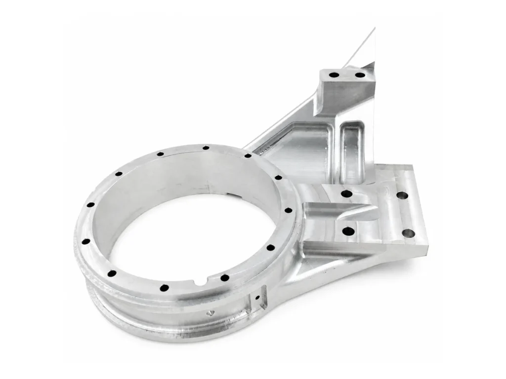
5-Axis CNC-Machined 6061-T6 Robotic Arm Component
This single prototype component was machined as one integral part from 6061-T6 aluminum for a robotic arm application. The geometry combines a large circular opening, locating holes, bearing bores, threaded features and functional faces accessed from multiple directions.
The bearing bores and locating holes required H7 diameter tolerances. Their positional and perpendicular relationships were controlled according to the drawing-defined GD&T requirements.
Project Information
- Material: 6061-T6 aluminum
- Manufacturing Process: 5-axis CNC machining
- Production Type: Single prototype
- Surface Condition: As-machined
- Application: Robotic arm component
- Critical Features: H7 bearing bores and locating holes
- Critical GD&T: Position and perpendicularity
- Inspection Methods: CMM, bore gauges and thread gauges
Manufacturing Challenges
- Maintain H7 diameter tolerances on the bearing bores and locating holes.
- Control the drawing-defined positional relationships between the locating features and functional interfaces.
- Maintain the required perpendicularity between the specified bores, faces and reference datums.
- Machine features from several directions while limiting accumulated setup error.
- Protect the finished bearing and locating features during subsequent machining and inspection.
Our Manufacturing Approach
- Use 5-axis CNC machining to access the circular opening, side features, locating holes and functional faces from multiple directions.
- Establish the machining and inspection strategy from the functional datums identified on the approved drawing.
- Prioritize the relationship between the bearing bores, locating holes and mating interfaces throughout the machining sequence.
- Use CMM inspection to verify drawing-defined position, perpendicularity and feature relationships.
- Use bore gauges to verify the specified H7 hole diameters.
- Use thread gauges to verify the specified threaded features.
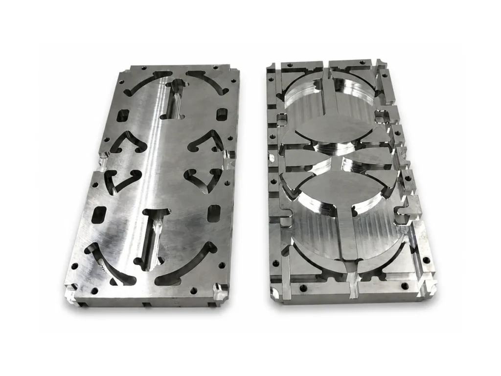
Small-Batch 3-Axis CNC-Machined 6061-T6 Aluminum Components
These components were produced in a small batch from 6061-T6 aluminum using 3-axis CNC machining. The two parts shown in the photograph are the same component design positioned to display its front and reverse sides. They are not left-hand and right-hand parts.
The original project drawing specified ISO 2768-mK as its general tolerance reference. The two major opposing faces also had demanding flatness and parallelism requirements.
Project Information
- Material: 6061-T6 aluminum
- Manufacturing Process: 3-axis CNC machining
- Production Type: Small batch
- Surface Condition: As-machined
- General Tolerance Reference: ISO 2768-mK, as specified on the original project drawing
- Critical Requirements: Flatness and parallelism of the two major opposing faces
- Known Inspection Methods: Optical projection inspection and thread gauges
Manufacturing Challenges
- Maintain the required flatness on both major machined faces.
- Control the parallelism relationship between the two opposing faces.
- Machine the front and reverse features while maintaining their relationship to the drawing-defined datums.
- Maintain consistent geometry and feature quality across the small production batch.
- Remove burrs without changing the edges, holes or functional profiles.
Our Manufacturing Approach
- Use 3-axis CNC machining with separate setups for the front and reverse features.
- Establish the relationship between the two major faces as an important part of process planning.
- Plan the machining sequence to maintain the drawing-defined flatness and parallelism requirements.
- Apply controlled finishing operations to the major faces after the primary material removal stages.
- Use optical projection inspection for applicable profiles and small geometric features.
- Use thread gauges to verify specified threaded features.
- Maintain consistent setup and inspection procedures across the small batch.
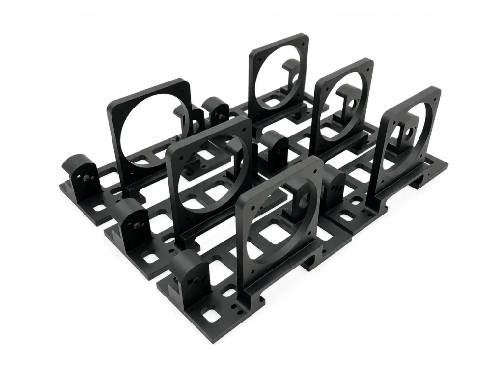
Repeat-Production 5-Axis CNC-Machined 6061 Aluminum Optical Motor Brackets
These motor mounting brackets were produced from 6061 aluminum for an optical equipment application. The components were manufactured using 5-axis CNC machining and supplied as repeat-production parts.
Critical requirements included the H7 motor mounting bore, H7 locating holes, flatness of the specified mounting faces and perpendicularity between the functional interfaces.
Project Information
- Material: 6061-T6 aluminum
- Manufacturing Process: 5-axis CNC machining
- Production Type: Repeat production
- Application: Motor mounting bracket for optical equipment
- Surface Treatment: black anodized finish
- Critical Features: H7 motor mounting bore and H7 locating holes
- Critical GD&T: Flatness and perpendicularity
- Inspection Methods: CMM, bore gauges and thread gauges
Manufacturing Challenges
- Maintain the H7 diameter requirement on the motor mounting bore.
- Maintain H7 tolerances on the locating holes used for accurate assembly.
- Control the flatness of the specified mounting and mating faces.
- Maintain the required perpendicularity between the motor bore, locating features and functional faces.
- Keep the critical feature relationships consistent across repeat-production batches.
- Protect functional fits and mating interfaces during the black surface treatment process.
Our Manufacturing Approach
- Use 5-axis CNC machining to access the motor bore, locating holes, threaded features and functional faces from multiple orientations.
- Establish the machining and inspection strategy from the functional datums defined on the approved drawing.
- Prioritize the relationship between the motor mounting bore, locating holes and mating faces throughout the machining sequence.
- Apply dedicated finishing operations to the specified flat and perpendicular interfaces.
- Consider surface-treatment allowance and masking requirements for critical fits where specified.
- Use CMM inspection to verify flatness, perpendicularity, position and functional feature relationships.
- Use bore gauges to verify the specified H7 bore and locating-hole diameters.
- Use thread gauges to verify specified threaded features.
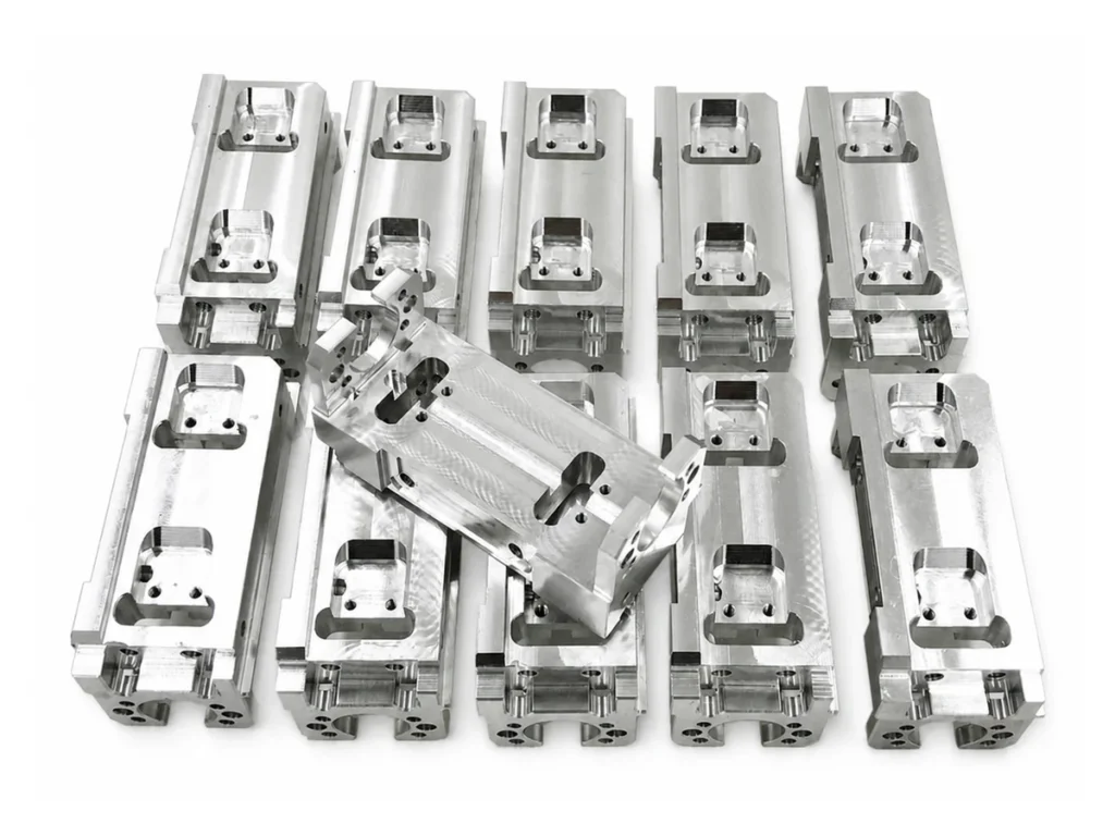
Small-Batch 5-Axis CNC-Machined 7075 Aluminum Industrial Components
These industrial equipment components were produced in a small batch from 7075 aluminum using 5-axis CNC machining. The parts combine precision bores, threaded features, machined faces and features accessed from multiple directions.
Critical requirements included bore diameter accuracy and the drawing-defined flatness, parallelism and perpendicularity relationships between the functional features.
Project Information
- Material: 7075 aluminum
- Manufacturing Process: 5-axis CNC machining
- Production Type: Small batch
- Application: Industrial equipment component
- Surface Condition: As-machined
- Critical Requirements: Bore diameter, flatness, parallelism and perpendicularity
- Inspection Methods: CMM, bore gauges and thread gauges
Manufacturing Challenges
- Maintain the specified bore diameters across every component in the small batch.
- Control flatness on the designated mounting and mating faces.
- Maintain parallelism between the specified opposing surfaces.
- Control perpendicularity between the precision bores, faces and drawing-defined datums.
- Maintain consistent feature relationships across parts machined in different production setups.
- Protect finished bores, threads and mating surfaces during handling and inspection.
Our Manufacturing Approach
- Use 5-axis CNC machining to access bores, side features, threaded holes and functional faces from multiple orientations.
- Establish the machining sequence from the functional datums defined on the approved drawing.
- Prioritize the relationship between the precision bores and critical mounting faces during process planning.
- Apply controlled finishing operations to the specified bores and functional faces.
- Maintain consistent setup, tool-control and inspection procedures across the small batch.
- Use CMM inspection to verify flatness, parallelism, perpendicularity and drawing-defined feature relationships.
- Use bore gauges to verify the specified internal diameters.
- Use thread gauges to verify the specified threaded features.
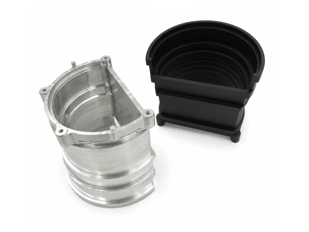
Repeat-Production CNC-Turned and 5-Axis Machined Optical Lens Barrel
This optical lens barrel was produced as a repeat-production component from 6061-T6 aluminum using a combination of CNC turning and 5-axis CNC machining.
The photograph shows the same component design in two surface conditions. One part retains its natural as-machined aluminum finish, while the other has received a black anodized finish.
Critical requirements included the positional relationship of the lens assembly features and the drawing-defined parallelism and perpendicularity between the optical bore, mounting interfaces and reference features.
Project Information
- Material: 6061-T6 aluminum
- Manufacturing Processes: CNC turning and 5-axis CNC machining
- Production Type: Repeat production
- Application: Optical lens barrel
- Surface Options: As-machined and black anodized
- Critical Requirements: Lens assembly position, parallelism and perpendicularity
- Inspection Methods: CMM, bore gauges and thread gauges
Manufacturing Challenges
- Maintain the required positional relationship of the features used to locate and assemble the optical lens.
- Control parallelism between the specified lens seating and mounting interfaces.
- Maintain perpendicularity between the optical bore, functional faces and drawing-defined datums.
- Transfer the primary datum relationships accurately between CNC turning and 5-axis machining operations.
- Maintain consistent geometry and inspection results across repeat-production batches.
- Account for the effect of black anodizing on precision bores, threads and mating features where required.
Our Manufacturing Approach
- Use CNC turning to establish the primary rotational geometry and concentric reference features.
- Use 5-axis CNC machining for side openings, mounting features, threaded holes and other non-axisymmetric geometry.
- Maintain a controlled datum strategy between the turning and 5-axis machining operations.
- Apply dedicated finishing operations to the lens assembly and mounting interfaces.
- Include the final surface condition in dimensional and inspection planning.
- Use CMM inspection to verify position, parallelism, perpendicularity and drawing-defined feature relationships.
- Use bore gauges to verify applicable internal diameters.
- Use thread gauges to verify specified threaded features.
- Maintain consistent machining and inspection procedures across repeat-production batches.
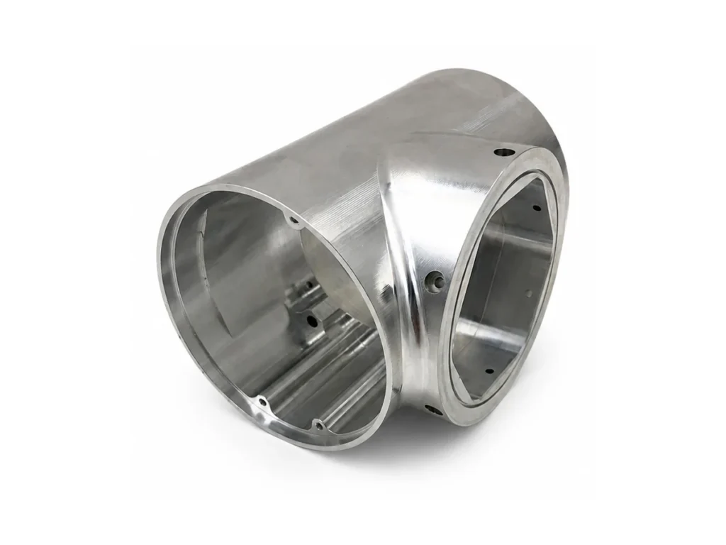
Small-Batch 5-Axis CNC-Machined 6061-T6 Robotic Arm Joint Component
This robotic arm joint component was produced in a small batch from 6061-T6 aluminum using 5-axis CNC machining. The part was machined as one integral component and includes a precision functional bore, curved external geometry, mounting features and interfaces accessed from multiple directions.
Critical requirements included an H7 bore diameter and the drawing-defined parallelism and perpendicularity relationships between the functional features and reference datums.
Project Information
- Material: 6061-T6 aluminum
- Manufacturing Process: 5-axis CNC machining
- Production Type: Small batch
- Application: Robotic arm joint component
- Surface Options: As-machined
- Critical Bore Requirement: H7 diameter tolerance
- Critical GD&T: Parallelism and perpendicularity
- Inspection Methods: CMM, bore gauges and thread gauges
Manufacturing Challenges
- Maintain the specified H7 diameter tolerance on the functional bore.
- Control parallelism between the specified mounting and mating interfaces.
- Maintain perpendicularity between the functional bore, faces and drawing-defined datums.
- Machine the curved geometry, internal features and side features from multiple directions.
- Limit accumulated setup error between features located on different orientations.
- Maintain consistent feature relationships across the small production batch.
Our Manufacturing Approach
- Use 5-axis CNC machining to access the functional bore, curved surfaces, mounting features and side features from multiple orientations.
- Establish the machining sequence from the functional datums defined on the approved drawing.
- Prioritize the relationship between the H7 bore and the specified mounting interfaces during process planning.
- Apply dedicated finishing operations to the precision bore and critical functional faces.
- Maintain consistent workholding, datum transfer and tool-control procedures across the small batch.
- Use CMM inspection to verify the H7 bore diameter, parallelism, perpendicularity and other drawing-defined feature relationships.
- Use bore gauges to verify applicable internal diameters.
- Use thread gauges to verify specified threaded features.
From Prototype to Repeat CNC Production
CNC machining can support the transition from a first functional part to bridge quantities and stable repeat orders. Each stage has a different purpose: learn from the prototype, control revisions during bridge production and preserve approved manufacturing information for future batches.
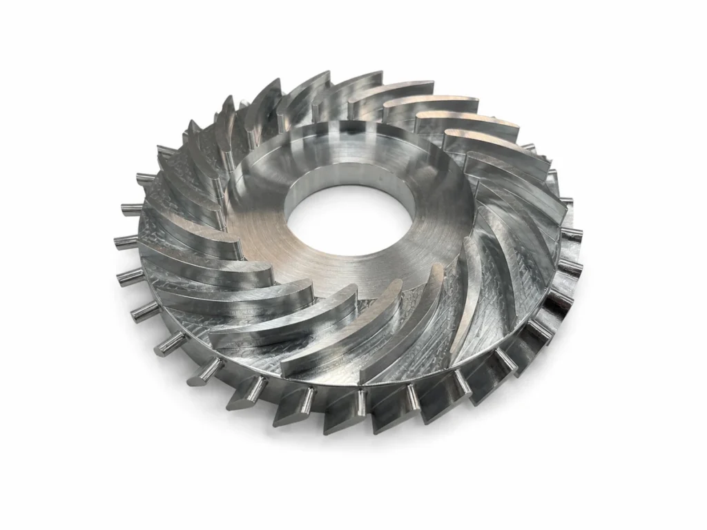
Prototype
Produce one part or a small initial quantity to verify fit, function, assembly and the planned machining strategy. Features still under development should be distinguished from dimensions already intended for production control.
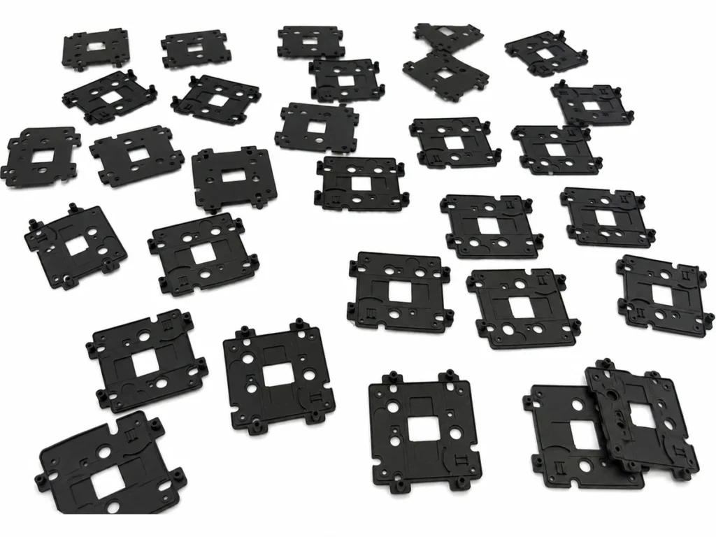
Bridge Production
Produce interim quantities for validation, pilot builds or market introduction while the design or long-term production route is being finalized. Drawing revisions, approved samples and first-off checks are controlled as the design becomes stable.
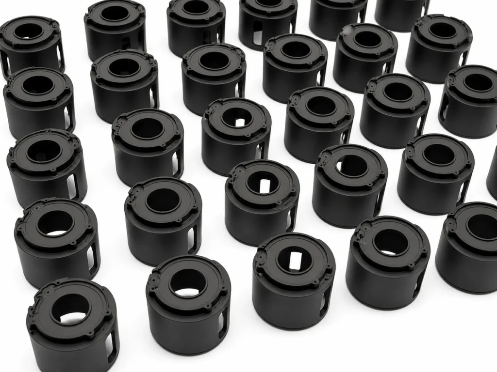
Repeat Production
Approved programs, workholding references, tool data and inspection checkpoints are retained for later batches. Changes to the drawing, material, finish or acceptance criteria are reviewed before production resumes.
Integrated Manufacturing Routes for Repeat Production
For recurring quantities, machining every feature from solid stock may no longer be the most economical route. Extrusions, die castings or forgings can place material closer to the final geometry, while CNC machining establishes the critical bores, threads, sealing faces and datum-related features. Tooling investment and lead time must be balanced against the expected production volume.
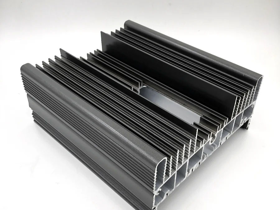
Aluminum Extrusion + CNC Machining
Suitable for components with a consistent cross-section, such as rails, heat sinks and long housings. The extrusion provides the basic profile, while CNC machining adds cut lengths, pockets, holes, threads, sealing faces and other controlled features. Profile tolerance, straightness and machining allowance are reviewed before the extrusion die is released.
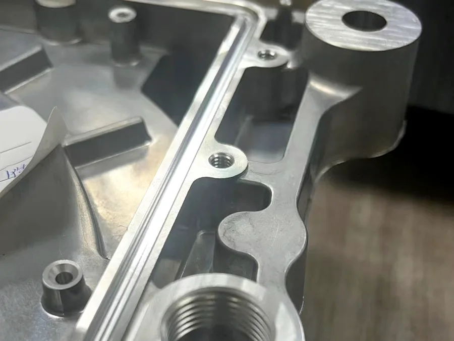
Die Casting + CNC Machining
Suitable for repeat components that benefit from near-net-shape walls, ribs, bosses and enclosed forms. CNC machining is then used for bores, threads, sealing surfaces and datum features that require tighter control than the casting alone. Tooling investment, draft, porosity and machining allowance must be considered together.
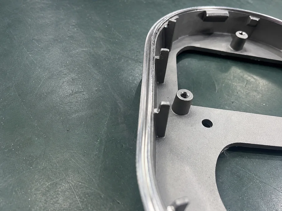
Forging + CNC Machining
A forged blank may be selected when controlled material flow, mechanical performance or reduced stock removal supports the application. CNC machining establishes the final interfaces, holes, threads and reference surfaces. Alloy, heat treatment, grain direction, forging tolerance and machining allowance must be defined together.
From Project Submission to Shipped CNC Parts
A defined six-step workflow keeps technical requirements, approvals and order status clear from initial file review through final shipment.
Submit Project Files
Upload the 3D CAD model and include a controlled 2D drawing when tolerances, threads, GD&T, surface finishes or inspection requirements must be defined.
Manufacturing Review
We assess the proposed machining route, workholding, feature access and drawing requirements that may affect production or verification.
Quotation and Approval
The quotation records the agreed process, quantity, finish, lead time and requested inspection documentation. Any proposed DFM changes are approved before production release.
Setup and First-Off Check
After programming and machine setup, the first stable part is checked against the defined production requirements before the remaining quantity proceeds.
Production and Final Inspection
Parts are machined with planned in-process checks, then cleaned, finished and given the agreed final inspection.
Packing and Shipment
Completed parts are protected, identified and packed for shipment. Dimensional reports, CMM reports, material certificates or finishing certificates are included when specified in the quotation.
CNC Tolerances Are Feature-Dependent
CNC tolerance capability must be evaluated feature by feature. Selected dimensional features may be held to ±0.01 mm after drawing and inspection review, but this value does not apply automatically to every dimension on the part. Thin walls, deep pockets, multi-setup relationships and dimensions affected by surface finishing may require different limits.
Unless otherwise specified on the controlled drawing, SAMSHION applies ISO 2768-mK as the default general tolerance standard. Individually toleranced dimensions and GD&T requirements take precedence.
Identify functional fits, datum relationships and critical GD&T on the controlled drawing. Our CNC machining tolerance guide explains how general and individual tolerances should be specified.
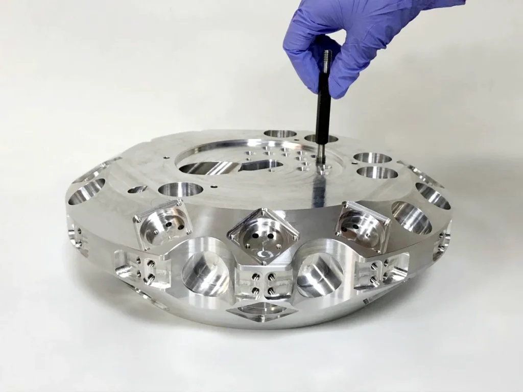
This multi-axis aluminum component combines precision bores, threaded holes, mating surfaces and datum-related features. Each characteristic requires its own tolerance and inspection method.
Applying the tightest tolerance to every dimension does not automatically improve part function. It can increase machining time, inspection effort, scrap risk and cost. Apply the tightest limits to features that control fit, alignment, sealing or motion, and use practical general tolerances elsewhere.
CNC Machining Materials
Material selection affects machining behavior, dimensional stability and finished-part performance. SAMSHION machines a broad range of metals and engineering plastics. Specify the exact grade, temper or supplied condition when mechanical properties or material traceability are important. For detailed comparisons, review our manufacturing materials guide.
Aluminum Alloys
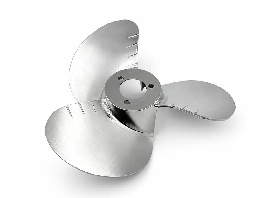
Aluminum combines low weight, good machinability and flexible finishing options. It is widely used for housings, brackets, fixtures, heat-management components and structural parts.
Common grades:
6061-T6, 7075-T6, 7050, 2024, 2A12, 6082, 5083, 5052, 6063 and MIC6
Finishing options:
As-machined, anodizing, chemical conversion coating, electroless nickel plating, media blasting, powder coating and polishing
Stainless Steels
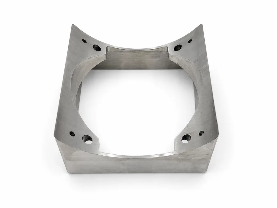
Stainless steel is selected where corrosion resistance, strength, cleanliness or temperature performance is important. Process planning must consider work hardening, tool access, heat generation and the required surface condition.
Common grades:
303, 304, 304L, 316, 316L and 17-4PH
Finishing options:
As-machined, passivation, electropolishing, media blasting and polishing
Carbon and Alloy Steels
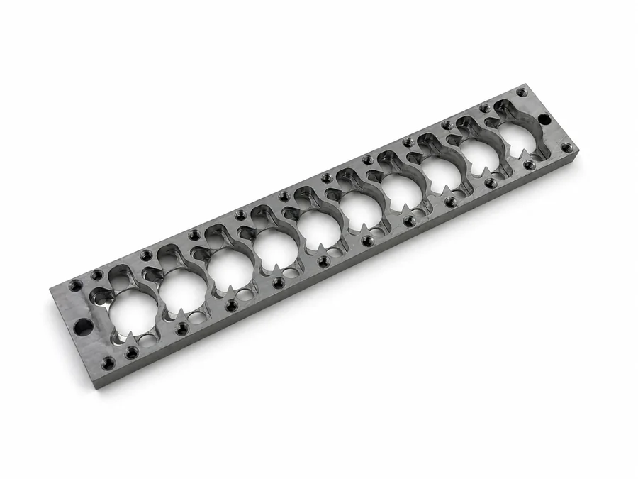
Carbon, alloy and tool steels provide strength, wear resistance and heat-treatment flexibility for shafts, fixtures, tooling components and industrial equipment parts. Material hardness and final heat-treatment condition should be confirmed before machining.
Common grades:
1018, 1045, 4140, 4340, D2 and H13
Finishing options:
As-machined, black oxide, nickel plating, zinc plating, powder coating and project-specific heat treatment
Copper and Brass Alloys
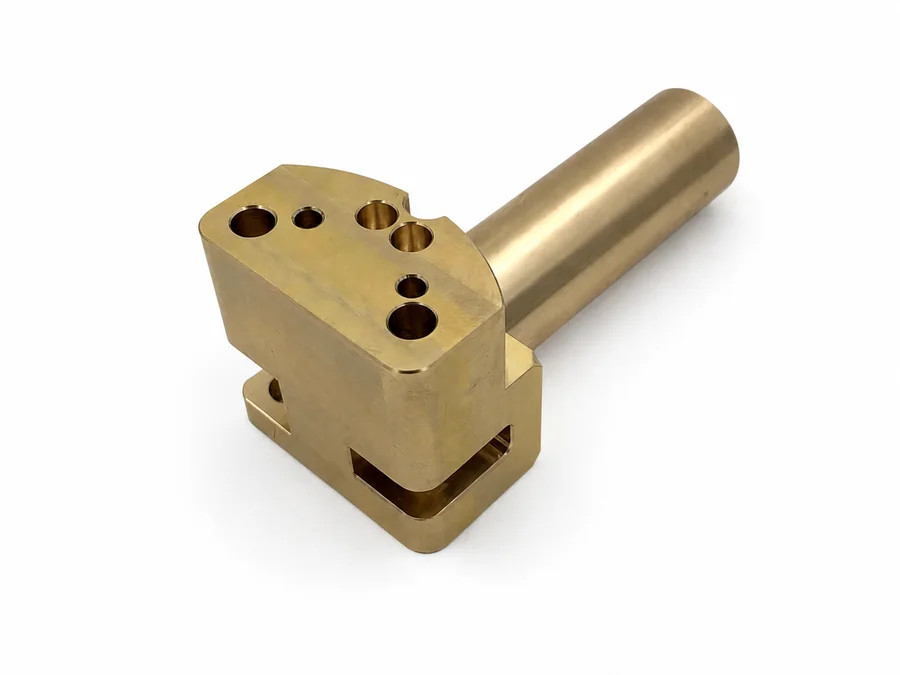
Copper alloys are used for electrical, thermal and electrode applications, while brass provides good machinability and corrosion resistance for fittings, connectors and precision components. Exact alloy and conductivity requirements should be stated on the drawing.
Common grades:
C101, C110, C145 and C360 brass
Finishing options:
As-machined, polishing, nickel plating and other project-specific coatings
Titanium Alloys
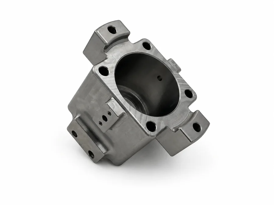
Titanium offers a high strength-to-weight ratio, corrosion resistance and biocompatibility. Machining requires controlled cutting conditions, suitable tooling, heat management and careful inspection of critical features.
Common grades:
Grade 2 and Grade 5 Ti-6Al-4V
Finishing options:
As-machined, media blasting, polishing and project-specific anodizing
Engineering Plastics
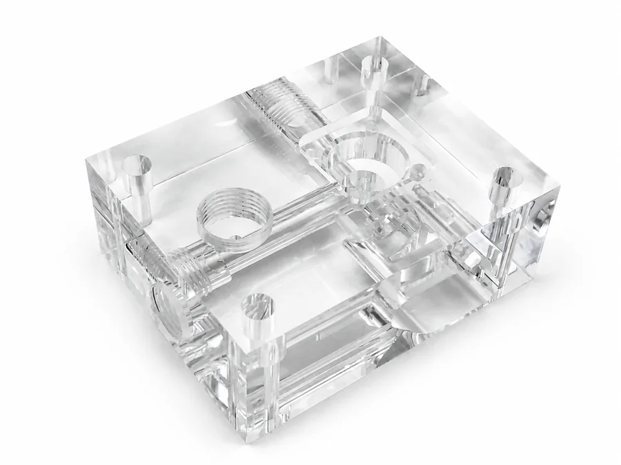
Engineering plastics can reduce weight, provide electrical insulation and support chemical or wear-resistant applications. Moisture absorption, thermal expansion, internal stress and dimensional stability must be considered when close tolerances are required.
Common grades:
POM/acetal, nylon, polycarbonate, ABS, PEEK, PPS, PTFE and polyethylene
Finishing options:
As-machined, deburred, polished or media-finished where the selected material permits
Availability and machining behavior can vary within the same material family. Identify any required temper, hardness, heat treatment or material certification on the drawing or purchase specification. Magnesium alloys, nickel alloys and other less common materials can be reviewed for project-specific feasibility.
Surface Finishes for CNC Machined Parts
Surface finishing is selected according to the material, part function, appearance and any dimensions that apply after finishing. Common options include as-machined surfaces, bead blasting, anodizing, polishing, plating and powder coating. Specify color, texture, coating thickness, masking and post-finish inspection requirements on the drawing or RFQ.
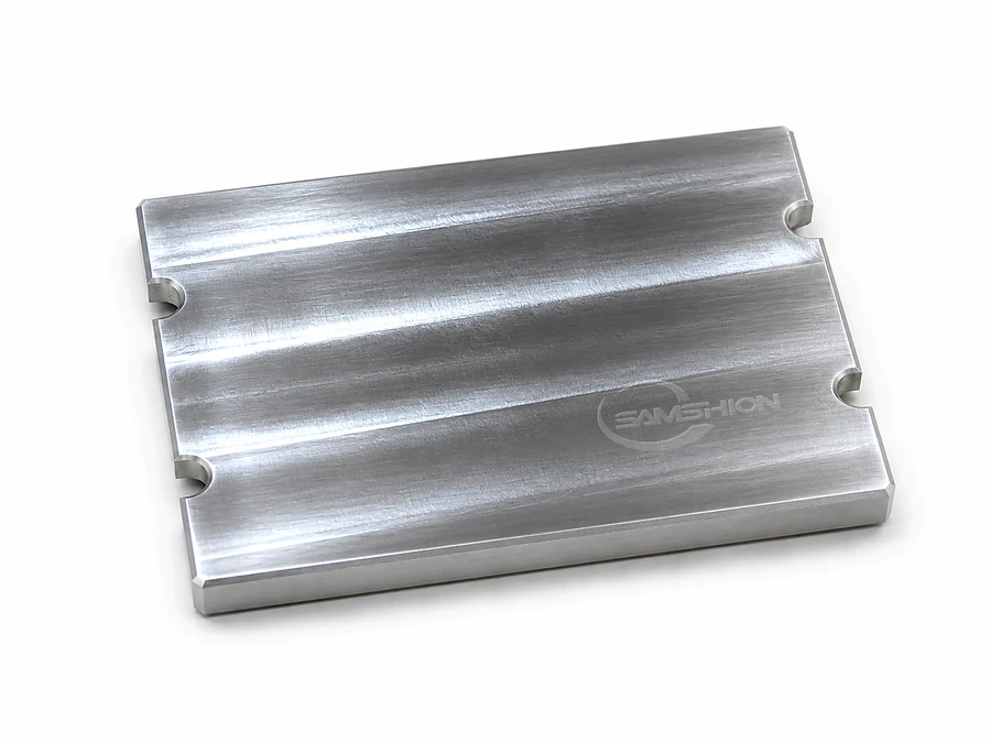
As-Machined
Visible tool marks remain unless a finer finish is specified. Our typical general finish is Ra 3.2 μm, while selected accessible surfaces may reach Ra 0.4 μm when geometry and process conditions allow.
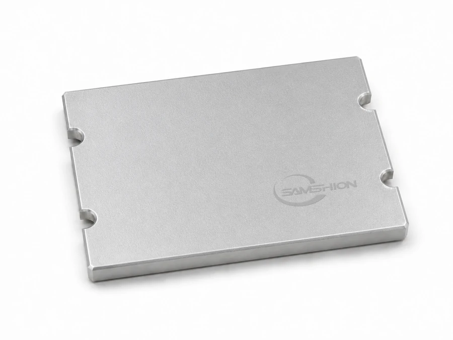
Bead Blasting
Bead blasting produces a uniform matte texture and reduces visible variation in machining marks. Critical bores, threads, sealing surfaces and electrical contact areas can be masked when specified.
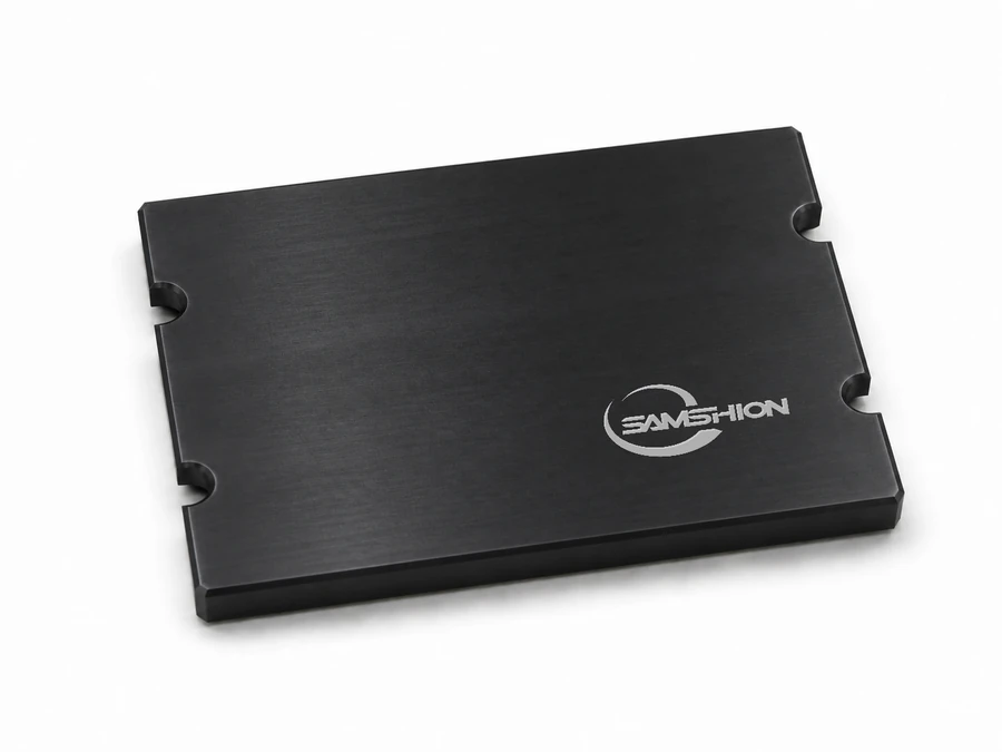
Anodizing
Anodizing is commonly used on aluminum parts to improve corrosion resistance, wear resistance and appearance. Anodizing type, color, coating thickness, masking and post-finish dimensions should be confirmed before production.
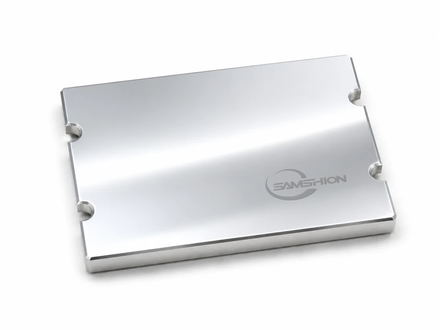
Polishing and Brushing
Polishing can reduce surface roughness on accessible features, while brushing creates a controlled directional texture. Final acceptance should be defined by surface roughness or an approved visual standard.
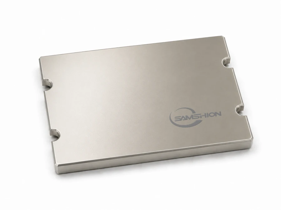
Electroless Nickel Plating
Electroless nickel plating provides a uniform metallic coating for suitable parts requiring corrosion or wear resistance. Coating thickness and dimensions that apply after plating must be identified on critical features.
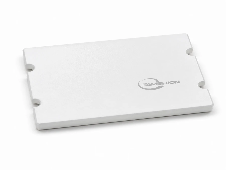
Powder Coating
Powder coating provides a durable colored finish for suitable metal parts. Specify the required color, gloss, texture, coating thickness and any threads, fits or contact surfaces that must remain uncoated.
Quality Control for CNC Machined Parts
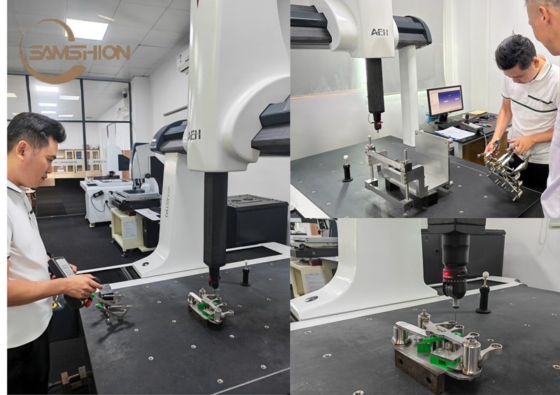
Quality control follows the approved drawing and the inspection scope confirmed for the order. Our ISO 9001-certified quality system combines an internal first-off check, risk-based in-process inspection, final verification and controlled inspection records. Formal reports and certificates are supplied when included in the quotation.
Review our quality assurance system for more information about the controls applied from production release through final acceptance.
- Confirm the drawing revision, material specification and critical inspection characteristics before production release.
- Verify the first stable part before production of the remaining quantity begins.
- Monitor dimensions affected by tool wear, heat or process variation during machining.
- Complete the agreed dimensional, visual and packaging checks before shipment.
- Record nonconformities and obtain customer authorization before accepting any deviation from the approved requirements.
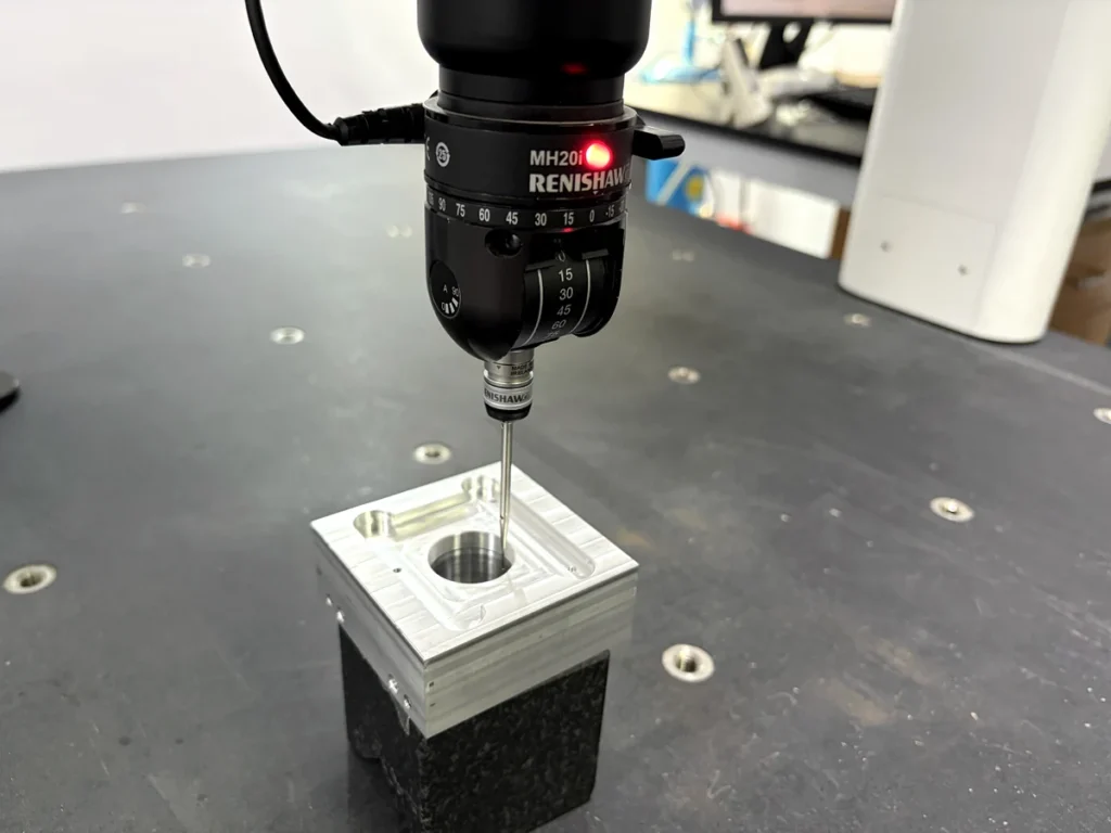
CMM Inspection
CMM inspection is used for selected dimensions, positions, profiles, datums and geometric relationships where coordinate measurement is appropriate. A customer-facing CMM report is supplied when included in the quotation.
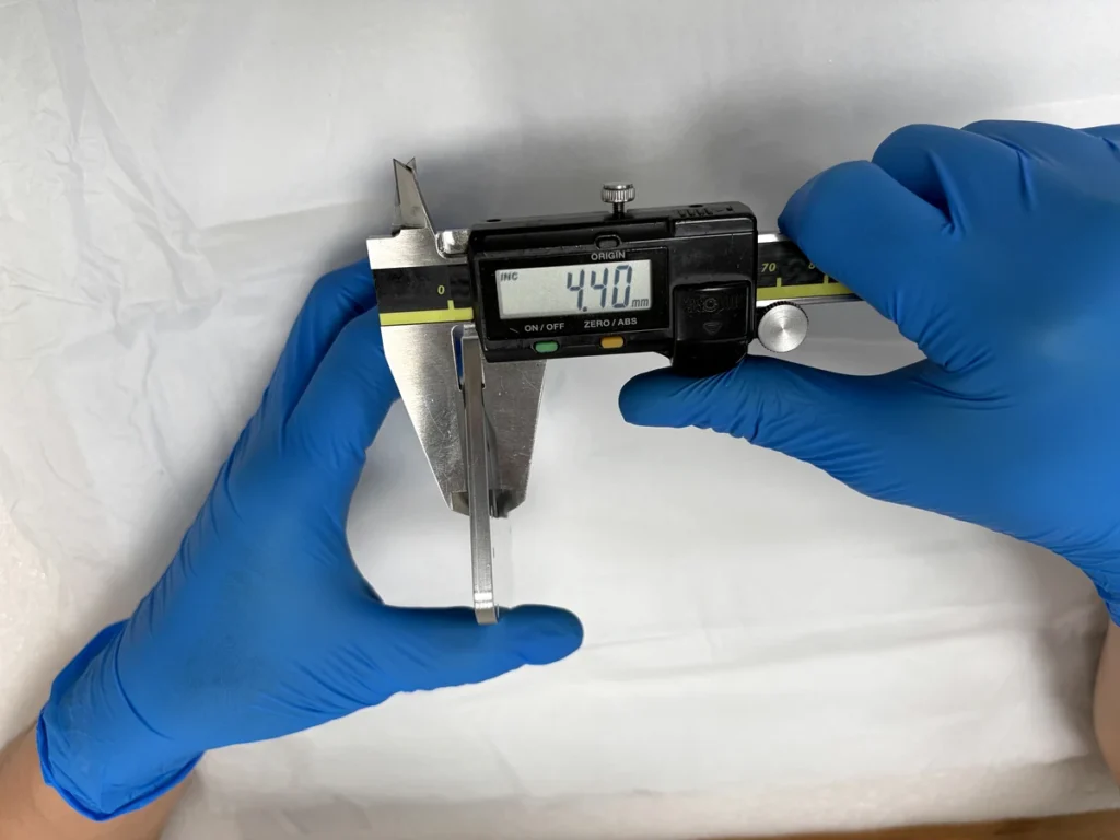
Dimensional Inspection
Calipers, micrometers, height gauges, depth gauges and bore gauges are selected according to feature size, access and required accuracy. Sampling frequency follows the inspection plan, production quantity and manufacturing risk.
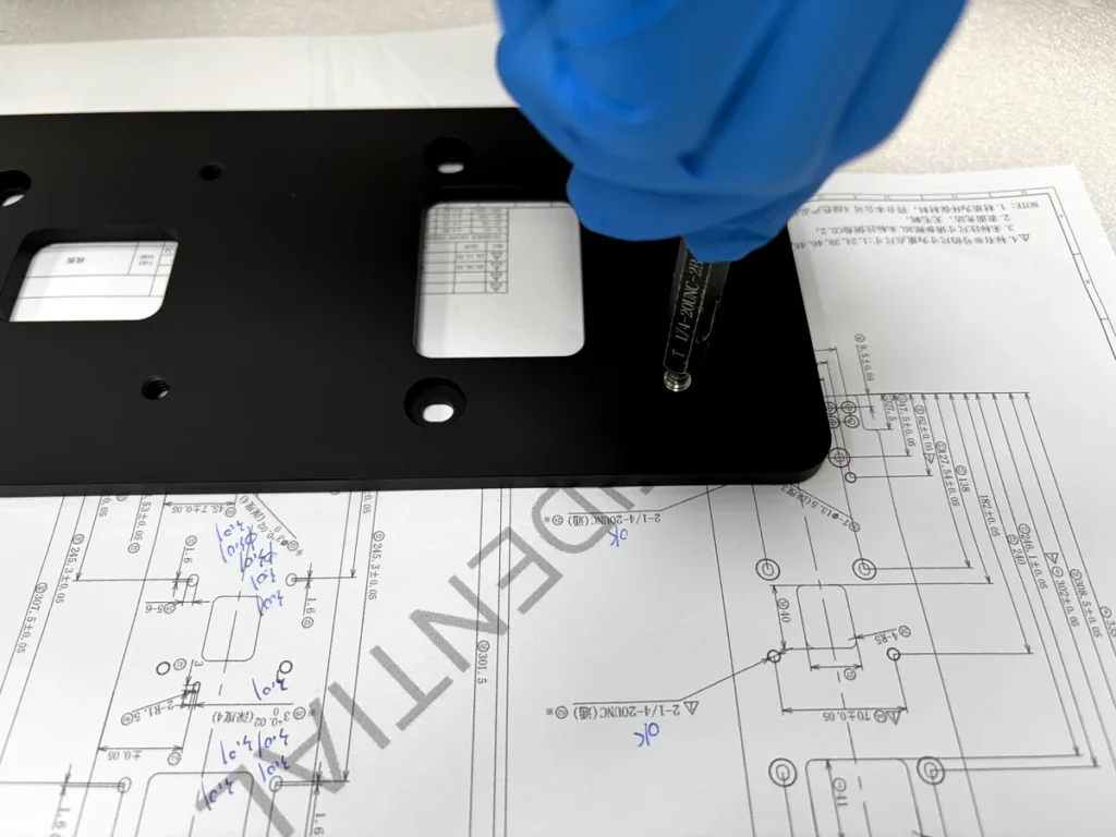
Thread and Functional Gauging
Thread plug gauges, thread ring gauges, pin gauges and bore gauges provide functional checks for specified threads, hole sizes and fits. Gauge selection follows the standard, nominal size, pitch, class and acceptance criteria defined on the drawing.
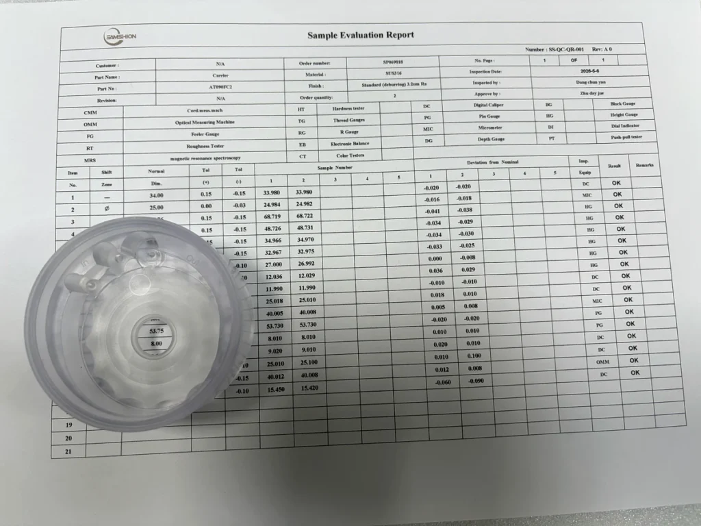
Inspection Records
Internal inspection records are controlled according to the applicable quality plan. Formal dimensional reports, CMM reports, first-article reports, material certificates and surface-treatment certificates are supplied when included in the quotation.
Design Guidelines for CNC Machined Parts
Small geometry choices can affect tool length, setup count, machining stability and inspection access. Use the following guidelines to identify features that may increase manufacturing difficulty before the design is released.
Provide Tool Access
Design features so the cutter and tool holder can approach from a practical direction. Deep cavities, hidden surfaces and obstructed features may require longer tools, additional setups, EDM or a design revision.
Use Practical Internal Radii
Internal corners are normally produced with round cutting tools. Larger internal radii allow the use of larger, more rigid cutters and can reduce machining time. Avoid zero-radius internal corners unless another process is specifically required.
Control Pocket Depth and Thin Walls
Deep pockets and thin unsupported walls can increase vibration, heat and dimensional variation. Where function permits, reduce unnecessary depth, increase wall support and avoid large differences in wall thickness.
Specify Threads Completely
Identify the thread standard, nominal size, pitch, tolerance class, handedness and required effective depth. Clearly distinguish through threads from blind threads and include any required lead-in, counterbore or relief.
Define Datums and Critical Interfaces
Use the controlled drawing to identify functional datums, mating surfaces and the geometric relationships that affect assembly. Apply the tightest requirements to features that control fit, alignment, sealing or motion.
Plan Finishing and Inspection Access
Allow for coating buildup, masking, contact points and access for the selected measuring method. Precision bores, threads, sealing faces and electrical-contact areas may require masking or post-finish machining.
For detailed examples and additional recommendations, review our CNC design for manufacturability guide.
What Is CNC Machining?
CNC machining is a subtractive manufacturing process in which computer-controlled equipment removes material from solid bar, plate or billet. Digital instructions control tool movement, feed, spindle speed and operation sequence, allowing parts to be produced repeatedly without a dedicated mold or die.
In CNC milling, the cutting tool rotates while the workpiece is secured in a fixture. In CNC turning, the workpiece rotates against the cutting tool. Multi-axis and mill-turn systems coordinate additional movement when a component combines features on several faces or includes both rotational and non-rotational geometry.
Learn more about how CNC machining works, including programming, machine types and typical applications.
When Is CNC Machining the Right Production Route?
CNC Machining Is a Strong Choice When
The prototype must represent the final metal or engineering plastic.
Critical bores, threads, datums, sealing faces or mating features require controlled machining.
The design may change during product development or validation.
Prototype, bridge or low volume production is required without dedicated tooling.
Repeat orders and product variants require controlled drawing revisions.
Inspection and traceability must follow an approved drawing.
Another Manufacturing Route May Be Better When
A constant cross section makes aluminum extrusion more economical.
High volume plastic production justifies injection molding tooling.
Stable repeat metal demand supports casting or forging followed by finish machining.
Thin sheet geometry is better produced through sheet metal fabrication.
Internal channels cannot be reached by cutting tools and require additive manufacturing.
Simple profiles with limited machining may be more economical using cutting or fabrication.
Process selection should reflect the complete production intent, including tooling investment, design maturity, expected quantity and downstream operations. Machining cost alone should not determine the production route.
CNC Machining FAQs
What files should I send for a CNC machining quote?
Send a 3D CAD model and include a controlled 2D drawing when the part has critical tolerances, GD&T, threads, surface-finish requirements or inspection notes. Please also identify the material grade, quantity, required finish and any reports or certificates needed with the order.
Do you support both prototypes and production parts?
Yes. SAMSHION has no minimum order quantity and can start with one prototype. We also support bridge production, small batches and repeat orders using the manufacturing information approved for the project.
What tolerances can CNC machining achieve?
Unless otherwise specified on the controlled drawing, our default general tolerance standard is ISO 2768-mK. Selected dimensional features may be held to ±0.01 mm after drawing and inspection review. This capability does not apply automatically to every feature on the part.
How do I choose between milling and turning?
CNC milling is generally used for parts dominated by flat faces, pockets, hole patterns and features on multiple sides. CNC turning is better suited to parts defined mainly by diameters, bores, shoulders, grooves and threads around a rotational centerline. Some components require both processes.
When should I consider 5-axis machining?
Consider 5-axis machining when a part has features on several orientations, complex surfaces or restricted tool access that would otherwise require multiple setups. Depending on the geometry, the project may use indexed 3+2 machining or simultaneous 5-axis movement.
Can CNC-machined parts receive surface finishing?
Yes. Available options include as-machined finishes, bead blasting, anodizing, passivation, electroless nickel plating, powder coating, polishing and other project-specific treatments. The selected finish must be compatible with the material and any tolerance-sensitive features.
What inspection documents are provided?
Every production batch receives an internal first-off check. Formal first-article reports, complete dimensional reports, CMM reports, material certificates and surface-treatment certificates are supplied when included in the quotation. These documents are not automatically included with every order.
What affects CNC machining lead time?
Lead time depends on material availability, part geometry, setup requirements, quantity, surface finishing and the agreed inspection documentation. Selected prototypes can be completed in as little as three working days after order and technical approval. Shipping time is not included.
Start Your CNC Machining Project
Upload your 3D CAD model and drawing for an engineering review and quotation. We will confirm the proposed manufacturing route, lead time and agreed inspection scope before production.