CNC manifold machining brings several requirements into one component: connected passages, accurately located ports, mounting interfaces and surfaces that must match the intended sealing arrangement. A hole can meet its diameter tolerance while its position is wrong for the mating part. A sealing face can look smooth while its flatness remains outside the drawing requirement. The manufacturing review therefore needs to consider how these features work together.
For a buyer ordering a custom machined manifold, the most useful starting point is a controlled drawing that defines the passage geometry, functional datums and acceptance requirements. At SAMSHION, we machine and inspect dimensions according to that drawing. Internal burrs and residual chips are usually cleaned manually, followed by visual checks of visible areas. Venting, water leakage and pressure tests are performed by the customer. These activities answer different questions and should be agreed separately.
What a manifold drawing needs to communicate
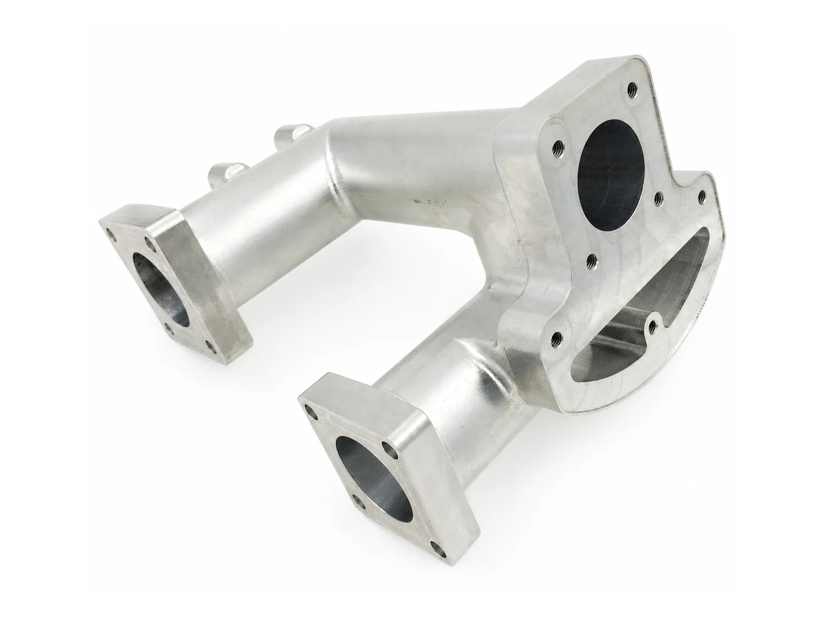
A manifold connects or distributes passages between interfaces. Some designs resemble rectangular blocks; others use branches, angled flanges or irregular external forms. The label alone does not identify the material, operating conditions, sealing method or required machining route. A hydraulic manifold block, a pneumatic distribution block and an automotive manifold can have very different requirements.
The CAD model should show the intended geometry, while the controlled drawing identifies requirements that cannot safely be inferred from shape. These include the thread standard, finished hole depth, datum references, geometric tolerances, sealing surface finish and any special internal edge condition. If a cross passage must connect to one port while staying separate from another, section views or a clear passage identification scheme help communicate that relationship.
For custom manifold manufacturing, identify which openings are operating ports, which are mounting or locating features and which exist only to provide machining access. An access hole that will later receive a closure is still a design feature. Its geometry, closure specification and responsibility for installation need agreement rather than an assumption during programming.
A manifold example from our CNC machining projects
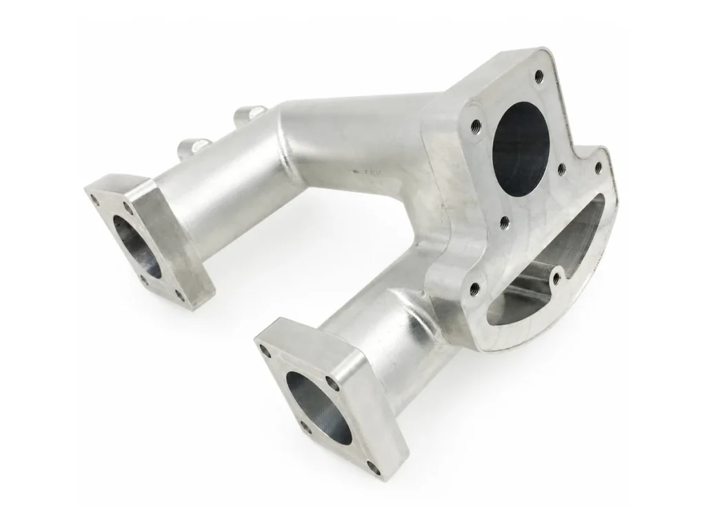
Our CNC machining service page includes an integral 6061-T6 aluminum automotive prototype manifold produced using 5-axis CNC machining. It combines angled mounting interfaces, deep intersecting passages, locating bores and threaded features. The project illustrates why tool access and the relationship between interfaces need to be reviewed together.
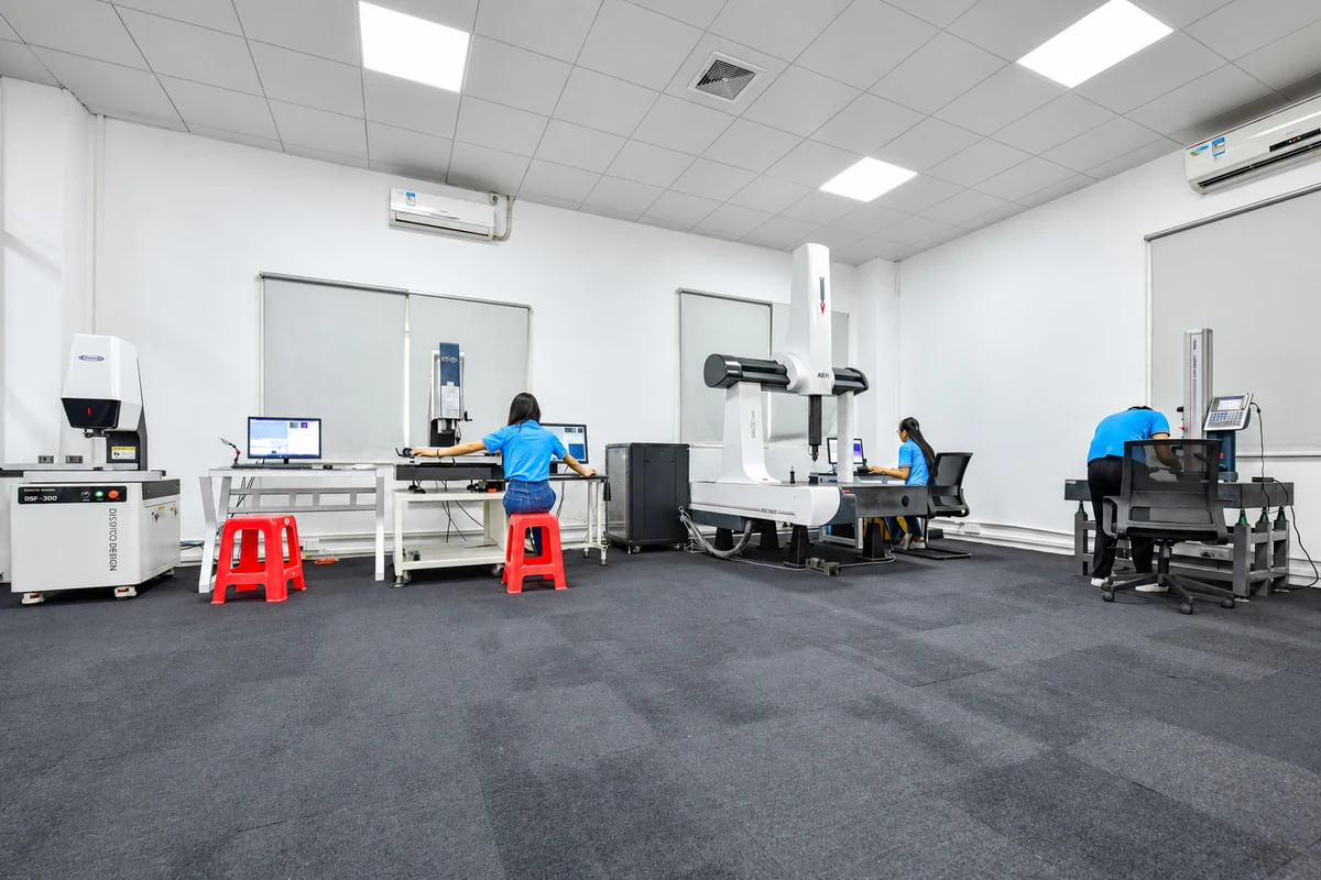
The published project describes CMM inspection of feature positions and interface relationships, with bore gauges and thread gauges used for applicable holes and threads. That dimensional inspection scope should not be read as a pressure-test or leak-test result. The same distinction applies when reviewing photographs of a machined manifold.
Establish the datum strategy before arranging the setups
Manifold port position matters in relation to the parts that will connect to it. A mounting face may establish the primary reference, with a locating bore or another specified feature defining the remaining orientation. The correct references come from the drawing, not simply from whichever outside surfaces are easiest to clamp.
Where ports enter from different directions, each setup must preserve the relationship to those references. Otherwise, separate operations can each produce acceptable local dimensions while the final port pattern or interface relationship falls outside tolerance. A machining plan should distinguish temporary locating surfaces from the functional datums used for final acceptance.
Our guide to datum transfer across multiple CNC setups explains this issue in more detail. For a manifold, the practical question is whether the process can preserve the specified relationship among passage axes, mounting holes and sealing faces after the part has been repositioned.
Five-axis access can help when a part has angled interfaces or several machining directions. It does not make every manifold a simultaneous 5-axis job, nor does it eliminate tool clearance, workholding or measurement constraints. The process is selected from the actual geometry, drawing requirements and accessible machining directions.
Plan intersecting holes as connected features
Cross hole machining needs attention at the intersection, not only at the visible entrance. As a drill breaks into an existing passage, the cutting conditions change. Burrs can form at an internal edge that is harder to reach than an external hole exit, and chips may collect where passages meet.
Sandvik Coromant guidance on irregular surface drilling identifies chip evacuation and deburring at cross holes as particular concerns. Its recommendations vary with the drilling tool and geometry. This supports reviewing the intersection and drilling sequence rather than applying one universal cutting recipe to every manifold.
Before machining, review the direction and depth of each passage, the intended overlap at an intersection and the material remaining between passages that must stay separate. A centerline intersection in the model is useful design information, but it does not replace dimensions and tolerances where the connection geometry is important to acceptance.
An underspecified junction can create avoidable disagreement. For example, a drawing may require two holes to communicate but leave unclear whether a partial opening is acceptable. If the opening size or transition shape is functional, the customer should define it or approve a manufacturable interpretation before the part is cut.
Tool reach and the far end of the passage
Deep passage machining introduces a difference between reaching a feature and controlling it. The tool, holder and fixture must clear the surrounding material throughout the operation. The available approach direction also affects whether the passage can be drilled and whether a specified finishing tool can reach the relevant section.
A diameter check near the entrance does not establish every characteristic at the far end. If straightness, position, form or a particular internal junction is critical, those requirements need a suitable verification plan. Our deep hole machining guide covers the broader relationship among depth, tool reach and inspection access.
Changing the direction of a hole, adding an access opening or splitting a component may improve access in some designs. These are design changes for customer approval. We do not alter a required passage connection or add an unapproved closure simply to make machining easier.
Separate passage diameters from precision locating bores
Not every hole in a machined manifold needs the same tolerance or machining method. A passage may have a different function from a locating bore, fitted connector seat or assembly reference. Giving all holes a tight fit tolerance can increase machining and inspection work without improving the feature that actually controls the assembly.
The selected process depends on hole diameter, tolerance, depth, material and access. Drilling may establish the hole, while reaming or boring may be appropriate for a specified precision feature. These methods are not interchangeable solutions for every location, especially where the tool must pass an interrupted surface or reach deep into the part.
Our drilling reaming and boring guide discusses how the drawing requirement affects that choice. For manifold drawings, identify the precision bore separately from the connected passage and define the relationship that matters. Diameter alone does not control a bore’s position relative to a mounting face or port pattern.
When using a fit designation, also identify the nominal size and applicable specification. A tolerance label should not be treated as evidence that every bore on the component has that requirement or that one gauge can establish every relevant characteristic.
Define manifold sealing faces beyond their appearance
A sealing interface needs a defined surface and a defined relationship to the assembly. Depending on the design, relevant requirements may include flatness, surface roughness, groove geometry, port position and the condition of edges near the seal. A photograph cannot establish those requirements or prove that they have been met.
Flatness and roughness describe different aspects of a surface. A face with fine visible machining marks can still have an unacceptable overall form. Conversely, a face that meets its flatness requirement may still have a scratch or local damage that matters to the sealing arrangement. Acceptance should follow the specified characteristics rather than a general instruction to make the surface look polished.
The Parker O-Ring Handbook, including its section on surface finish of seal faces, distinguishes surface form, waviness and roughness and provides application-dependent guidance. The customer should select the applicable sealing requirements. A single roughness value is not a universal specification for all manifold sealing faces.
Where a design includes a seal groove, communicate the groove dimensions, tolerances and required edge condition. Our O ring groove machining guide covers that feature in more detail. Do not assume a generic edge break is acceptable where it changes a sealing land, groove width or fitted interface.
The final surface condition also belongs on the drawing or order. If a coating or other treatment is required, clarify which dimensions apply after treatment and whether particular interfaces need protection. An as-machined manifold and a surface-treated manifold should not be accepted against conflicting assumptions about their finished dimensions.
Specify threaded ports and access features completely
A thread callout needs more than a nominal diameter. Identify the thread standard, size, pitch or threads per inch, tolerance class where applicable and required usable depth. For a blind threaded feature, distinguish full thread depth from the drilled depth and the space needed beyond the usable thread.
The surrounding seat, spotface or sealing geometry may be just as important as the thread. A correct thread does not establish that a connector will seat correctly or that the assembled interface will seal. The thread and its adjacent features need to match the customer’s specified connection design.
Our threaded hole machining guide explains the information needed to review tapping and thread milling. On a manifold drawing, also identify whether access plugs, connectors or seals are supplied and installed by the customer or included in a separately agreed supply scope. A photo of an open port does not establish the delivered assembly configuration.
Manual cleaning and checks of visible areas
At SAMSHION, burrs and residual chips are usually cleaned manually. After cleaning, we visually check visible areas. This describes the current inspection scope; it does not establish that every hidden intersection or enclosed passage has been observed.
The distinction matters because an accessible hole entrance and a concealed internal junction present different inspection opportunities. If a drawing includes a special internal burr limit or cleanliness requirement, the method of demonstrating compliance needs agreement before production. A general instruction such as clean thoroughly does not define the size, quantity or location of acceptable residual contamination.
Deburring also needs to preserve the functional geometry. Removing an accessible burr should not enlarge a fitted hole, round a specified sharp transition or damage the adjacent sealing surface. Our CNC deburring and edge inspection guide discusses why the drawing’s edge requirements should guide that work.
For an application requiring evidence beyond visible-area checks, the customer should specify what must be verified and what record is required. That additional requirement needs a separate feasibility review. A numerical cleanliness limit, for example, needs a defined verification method rather than a statement that the accessible surfaces look clean.
Match dimensional inspection to each drawing requirement
Manifold dimensional inspection should start with the characteristics on the drawing. The instrument and measurement approach are selected for the feature, access and tolerance. No single method establishes all dimensions, hidden conditions and functional performance of a component.
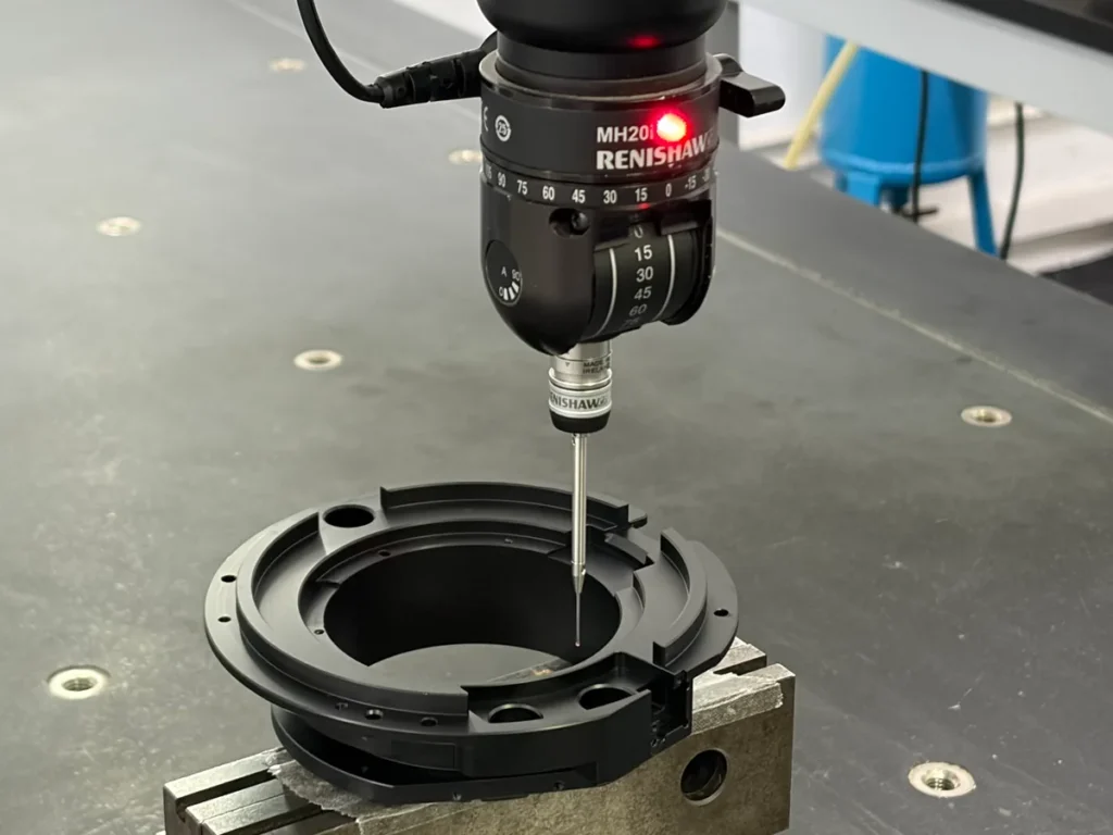
These are inspection planning categories, not a statement that every listed method is used on every order. The manifold project on our service page used CMM inspection, bore gauges and thread gauges for the features described there. A different manifold may require a different plan.
A CMM can establish accessible geometric relationships when the measurement strategy is appropriate. It does not automatically verify an entire concealed passage. Similarly, a pin gauge or bore gauge check does not by itself establish a hole’s position, the condition of an internal intersection or the performance of an assembled seal.
When a dimensional report is required, agree the drawing revision and report scope before production. Our guide to CNC inspection reports explains the differences among common records. A material certificate, a dimensional report and a customer pressure-test record provide different information and should remain identifiable as separate documents.
Keep dimensional acceptance separate from customer functional testing
For the work described here, SAMSHION machines and inspects dimensions according to the customer drawing. The customer carries out venting, water leakage and pressure tests. A dimensional inspection result should therefore not be described as a pressure rating, a leak-tightness certificate or approval for a particular operating condition.
The customer should define the functional test and acceptance criteria appropriate to the assembled product. Connectors, seals, closures and the mating assembly can all be relevant to that evaluation. There is no general test pressure or leak acceptance value that can be inferred from a manifold photograph or from the fact that it was CNC machined.
If the customer finds a functional issue during testing, useful feedback includes the controlled drawing revision, affected location, assembly configuration and relevant test observations. That information helps distinguish a dimensional nonconformance from a design or assembly question. It does not justify changing an internal passage or sealing interface without an approved revision.
Information to include in a custom manifold machining enquiry
Send the current 3D model together with a controlled 2D drawing. For a manifold with intersecting holes and multiple interfaces, the following information makes the manufacturing review more useful.
- Identify the material grade, quantity and required delivery date.
- Show passage connections, blind depths and any passages that must remain separate.
- Define the functional datums, port positions and critical interface relationships.
- Specify precision bore tolerances, thread callouts and usable thread depths.
- Identify sealing surfaces, groove dimensions and applicable finish requirements.
- State the final surface condition and any supplied or customer-installed components.
- Define special burr or cleanliness requirements and the evidence needed for acceptance.
- Identify dimensional reporting requirements and keep customer functional tests separate.
If the design is still changing, mark the drawing revision clearly and identify unresolved features before the quotation is released. A change to one port can affect tool access, nearby wall thickness, the connection to another passage or the fixture used for a later operation. The review should consider those consequences together rather than treating the revised hole as an isolated edit.
To request a drawing review, contact SAMSHION with the model, drawing and acceptance requirements. We can assess the machining route and dimensional inspection scope without assuming that unspecified functional tests are included.
Common questions about CNC machined manifolds
Does every manifold need five axis CNC machining
No. The selected route depends on the feature directions, tool access, workholding and drawing requirements. Some designs suit conventional milling setups, while angled interfaces or restricted access may benefit from multi-axis machining. The number of axes alone does not establish the quality of the finished part.
Can an entrance diameter check verify a deep cross passage
It can verify the characteristic covered by that particular check, but it does not establish every dimension or condition farther inside the part. Critical internal geometry and acceptance requirements need an appropriate verification plan.
Does a smooth sealing face mean the manifold will not leak
No. Appearance does not establish flatness, specified roughness, seal condition or assembled performance. Machine the interface to the drawing, inspect the specified characteristics and keep customer leakage testing separate from dimensional acceptance.
Are hidden intersections visually checked after manual cleaning
Our routine visual check covers visible areas. It should not be described as inspection of all concealed internal passages. Additional internal verification or cleanliness evidence must be specified and reviewed separately.
Who performs pressure and water leakage tests
For the supply scope described in this article, these tests are performed by the customer. SAMSHION’s machining and drawing-based dimensional inspection do not replace those functional tests.