Internal threads are common, but they create avoidable quoting and production problems when a drawing shows only a nominal thread size. The machinist still needs to understand thread standard, class, effective depth, hole depth, entry condition and how the feature will be inspected.
Tapping and thread milling can both produce useful threads. Neither is universally better. The correct process depends on the material, thread diameter, depth, machine capability, chip risk, part value and quantity.
Scope, Search Intent and Technical Boundary
This article addresses internal-thread process selection and drawing completeness. It is narrower than the general CNC service page’s brief threading section. For broader geometry and specification guidance, use the design for manufacturability guide alongside this feature-level discussion.
Use this guide to prepare an RFQ, review DFM comments and define acceptance evidence for CNC threaded holes; it is not a universal capability promise.
Key Takeaways
- Specify thread standard, size, class and required engagement.
- Separate full thread depth from drilled hole depth in blind features.
- Thread milling can reduce tap-breakage risk and improve adjustability on suitable parts.
- Tapping can be efficient for stable, repetitive holes when chip control is reliable.
- Provide gauge and tool access near shoulders, counterbores and intersecting features.
What a Complete Thread Callout Needs
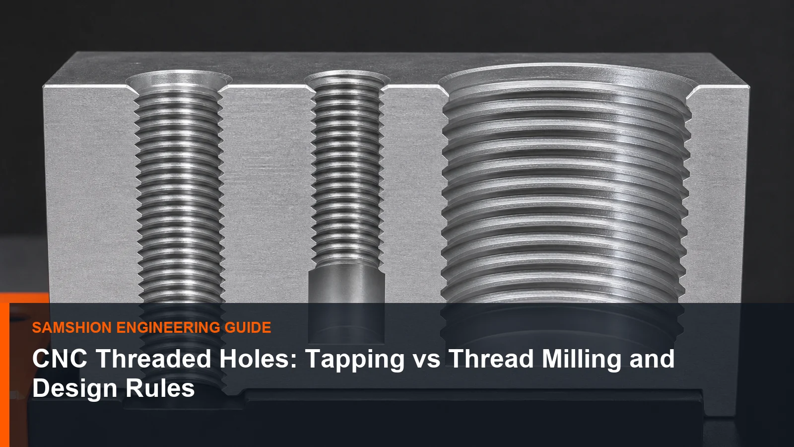
The drawing should identify the thread system, nominal size, pitch or threads per inch, class and depth. If the thread is blind, distinguish the usable full-thread depth from the total drilled depth. A bottoming tap still needs runout and chip space.
For helicoil or other insert systems, specify the insert standard and installed requirement rather than only the final nominal thread. For the corresponding manufacturing decision and capability context, consult SAMSHION’s CNC turning services.
When Tapping Makes Sense
A tap forms the thread with a tool matching the thread geometry. It can be fast and consistent for common sizes, suitable materials and stable holes. Spiral-point, spiral-flute, forming and other tap styles manage chips and material differently.
The main risk is that the tool occupies the complete thread diameter. A broken tap in a valuable component can be difficult to remove. Hole size, alignment, lubrication and chip evacuation must be controlled. For the corresponding manufacturing decision and capability context, consult SAMSHION’s CNC fixturing and setup guide.
When Thread Milling Makes Sense
A thread mill uses a helical toolpath to generate the thread. One tool can sometimes cover multiple diameters with the same pitch, and the thread size can be adjusted through the program. The tool can often be removed if it fails because its diameter is smaller than the finished thread. For the corresponding manufacturing decision and capability context, consult SAMSHION’s CNC milling services. Tool selection and application limits can be cross-checked against the Sandvik Coromant threading application guide before the production method is released.
Thread milling is attractive for large threads, tough materials, thin walls, blind holes near a shoulder and expensive parts. It requires suitable interpolation, adequate tool rigidity and enough space for the cutter.
Design Blind Holes, Counterbores and Intersections
Leave enough bottom clearance for the drill point, tap lead or thread-mill runout. Do not place a cross hole through the final thread engagement without reviewing burr access. Counterbores should allow the tool and gauge to enter without interference.
Avoid thread depth that exceeds functional engagement merely to make the drawing look robust. Excessive depth adds cycle time and tool risk without necessarily increasing joint strength.
Inspection and Functional Verification
GO and NO-GO gauges are common for standard internal threads, but special or large threads may require other methods. Clarify whether the supplier must provide gauge results, dimensional data or only a certificate of conformance.
If the mating fastener is nonstandard, supply its specification or a functional master. Thread acceptance should match assembly intent.
Threaded-Hole RFQ Checklist
- Thread standard, size, pitch and class
- Usable thread depth and total hole depth
- Through or blind condition and bottom clearance
- Insert, coating or locking requirements
- Gauge type, report and mating-fastener information
Engineering Variables to Confirm Before Quotation
Thread standard, pitch, class and usable engagement
For CNC threaded holes, thread standard, pitch, class and usable engagement requires an explicit engineering decision. Resolve this point while the process route is still flexible. Ask which function depends on it, which datum or material state establishes it, and at what production stage it will be accepted. A clear answer prevents manufacturing convenience from replacing functional intent. Keep the decision with the job record, because a verbal answer cannot control repeat work.
Blind-hole drill depth versus full-thread depth
For CNC threaded holes, blind-hole drill depth versus full-thread depth requires an explicit engineering decision. Treat this as an RFQ input, not a shop-floor surprise. Ask which function depends on it, which datum or material state establishes it, and at what production stage it will be accepted. Its interpretation changes datum selection, setup count and verification effort. Tie any relaxation to the actual function rather than to a generic shop capability statement.
Material chip behavior and tap-breakage consequence
For CNC threaded holes, material chip behavior and tap-breakage consequence requires an explicit engineering decision. Do not allow a default title-block tolerance to answer this question indirectly. Ask which function depends on it, which datum or material state establishes it, and at what production stage it will be accepted. It may determine whether a flexible prototype route remains suitable for repeat production. The review is complete only when production and inspection use the same definition.
Thread-mill interpolation space and tool rigidity
For CNC threaded holes, thread-mill interpolation space and tool rigidity requires an explicit engineering decision. Use this requirement to frame the first technical review. Ask which function depends on it, which datum or material state establishes it, and at what production stage it will be accepted. Its interpretation changes datum selection, setup count and verification effort. The review is complete only when production and inspection use the same definition.
Thin-wall response to forming or cutting torque
For CNC threaded holes, thin-wall response to forming or cutting torque requires an explicit engineering decision. Reconcile the model, drawing and purchase specification at this point. Ask which function depends on it, which datum or material state establishes it, and at what production stage it will be accepted. The decision can move a feature from a routine check to a controlled first-article characteristic. The review is complete only when production and inspection use the same definition.
Gauge access near counterbores and shoulders
For CNC threaded holes, gauge access near counterbores and shoulders requires an explicit engineering decision. Reconcile the model, drawing and purchase specification at this point. Ask which function depends on it, which datum or material state establishes it, and at what production stage it will be accepted. A clear answer prevents manufacturing convenience from replacing functional intent. Record the agreed interpretation beside the revision so later orders do not reopen the same ambiguity.
Failure Modes and Root-Cause Diagnosis
A blind hole has insufficient runout below the required full thread
A characteristic failure for CNC threaded holes occurs when a blind hole has insufficient runout below the required full thread. The observation is evidence, not yet a root cause. Evaluate material behavior, support, cutter condition, programmed sequence and the measurement alignment as separate hypotheses. Preserve the failed part condition long enough to distinguish cutting evidence from handling or finishing damage. If the cause remains uncertain, contain the lot and expand the trial before releasing more material.
A tap packs chips at the bottom and damages an expensive part
A characteristic failure for CNC threaded holes occurs when a tap packs chips at the bottom and damages an expensive part. The observation is evidence, not yet a root cause. Evaluate material behavior, support, cutter condition, programmed sequence and the measurement alignment as separate hypotheses. Check whether the indication follows the cutter, the setup, the material lot or the inspection alignment. Confirm that the remedy does not transfer error to a mating feature or datum.
The thread passes a fastener test but fails the specified class gauge
A characteristic failure for CNC threaded holes occurs when the thread passes a fastener test but fails the specified class gauge. The observation is evidence, not yet a root cause. Evaluate material behavior, support, cutter condition, programmed sequence and the measurement alignment as separate hypotheses. Repeat the measurement with a second suitable method before rewriting the machining program. Do not hide the symptom with manual blending unless the drawing explicitly permits that edge condition.
A cross hole leaves an inaccessible burr inside the thread
A characteristic failure for CNC threaded holes occurs when a cross hole leaves an inaccessible burr inside the thread. The observation is evidence, not yet a root cause. Evaluate material behavior, support, cutter condition, programmed sequence and the measurement alignment as separate hypotheses. Compare the blank, clamped part, released part and finished part to locate the stage where the error appears. Update the setup sheet and inspection plan so the fix survives the next batch.
Process Controls for a Repeatable Result
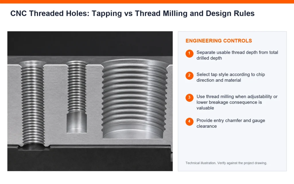
Separate usable thread depth from total drilled depth
A process plan for CNC threaded holes can control this risk by choosing to separate usable thread depth from total drilled depth. The action is useful only when it targets a named source of variation. Before release, consider access, local stiffness, heat flow and the acceptance condition of neighboring features. Prove the control on the first article and retain the before-and-after evidence. Use the simplest method that reliably protects the stated function.
Select tap style according to chip direction and material
A process plan for CNC threaded holes can control this risk by choosing to select tap style according to chip direction and material. The action is useful only when it targets a named source of variation. Before release, consider access, local stiffness, heat flow and the acceptance condition of neighboring features. Use a short prototype trial first; formalize fixture, sampling and tool-life rules for repeat orders. Escalate a trend before it crosses the acceptance limit.
Use thread milling when adjustability or lower breakage consequence is valuable
A process plan for CNC threaded holes can control this risk by choosing to use thread milling when adjustability or lower breakage consequence is valuable. The action is useful only when it targets a named source of variation. Before release, consider access, local stiffness, heat flow and the acceptance condition of neighboring features. Review adjacent walls, threads, sealing lands and datums for unintended consequences. A stable process is demonstrated by evidence across parts, not by one favorable measurement.
Provide entry chamfer and gauge clearance
A process plan for CNC threaded holes can control this risk by choosing to provide entry chamfer and gauge clearance. The action is useful only when it targets a named source of variation. Before release, consider access, local stiffness, heat flow and the acceptance condition of neighboring features. Pair the control with a measurable limit rather than a general workmanship instruction. Escalate a trend before it crosses the acceptance limit.
Review insert requirements before selecting the pilot hole
A process plan for CNC threaded holes can control this risk by choosing to review insert requirements before selecting the pilot hole. The action is useful only when it targets a named source of variation. Before release, consider access, local stiffness, heat flow and the acceptance condition of neighboring features. Verify that the method remains stable after tool change, unclamping or finishing. Repeat production should not depend on an operator remembering an undocumented exception.
Control tool life before thread size drifts
A process plan for CNC threaded holes can control this risk by choosing to control tool life before thread size drifts. The action is useful only when it targets a named source of variation. Before release, consider access, local stiffness, heat flow and the acceptance condition of neighboring features. Review adjacent walls, threads, sealing lands and datums for unintended consequences. Retain enough evidence to distinguish setup drift from material or tool variation. The applicable production route and process controls are outlined in SAMSHION’s 6061 aluminum CNC machining guide.
Inspection Strategy and Acceptance Evidence
GO and NO-GO gauge result for standard threads
Inspection of CNC threaded holes should explicitly address GO and NO-GO gauge result for standard threads. First define the characteristic, datum reference and part condition represented by the result. Choose equipment whose uncertainty is small enough to support the stated decision. Identify whether each result is measured, visually verified or supported only by material documentation.
Effective usable engagement
Inspection of CNC threaded holes should explicitly address effective usable engagement. First define the characteristic, datum reference and part condition represented by the result. Use a functional gauge when fit matters more than a single isolated coordinate. When results disagree, compare alignment, force, temperature and feature definition before averaging values.
Entry chamfer and first complete thread
Inspection of CNC threaded holes should explicitly address entry chamfer and first complete thread. First define the characteristic, datum reference and part condition represented by the result. Use a functional gauge when fit matters more than a single isolated coordinate. Agree the acceptance method before machining when a supplier and customer could reasonably measure differently.
Cross-hole burr condition
Inspection of CNC threaded holes should explicitly address cross-hole burr condition. First define the characteristic, datum reference and part condition represented by the result. Build the datum alignment exactly as defined on the controlled drawing. Report nominal, limits and actual result; do not substitute a certificate statement for measured data. The available verification and reporting workflow is summarized in SAMSHION’s quality assurance.
Insert installation depth and locking feature when applicable
Inspection of CNC threaded holes should explicitly address insert installation depth and locking feature when applicable. First define the characteristic, datum reference and part condition represented by the result. Measure in the delivered condition whenever coating, heat treatment or release affects the result. Retain traceability to the part revision and the production stage at which acceptance occurred.
Cost, Lead Time and Quotation Transparency
Number and size of threaded holes
In a quotation for CNC threaded holes, number and size of threaded holes can influence both lead time and total manufacturing cost. Secondary finishing and final-state inspection can make this more influential than raw cycle time. Compare flexible and dedicated production routes when order volume could justify either.
Blind depth and difficult access
In a quotation for CNC threaded holes, blind depth and difficult access can influence both lead time and total manufacturing cost. Secondary finishing and final-state inspection can make this more influential than raw cycle time. State the assumed interpretation, included records and conditions that would trigger requotation.
Special gauges or inserts
In a quotation for CNC threaded holes, special gauges or inserts can influence both lead time and total manufacturing cost. Dedicated support or gauging may raise initial cost while lowering variation across a batch. Compare flexible and dedicated production routes when order volume could justify either.
Risk of scrapping a high-value nearly finished part
In a quotation for CNC threaded holes, risk of scrapping a high-value nearly finished part can influence both lead time and total manufacturing cost. It can add material preparation, a dedicated cutter or a separate verification step. Identify whether the commercial risk comes from capability, ambiguity or verification effort.
A Practical Engineering Review Sequence
Start with the function protected by thread standard, pitch, class and usable engagement. Mark the related datums, interfaces and delivered-state requirements on the controlled drawing. The manufacturing review can then choose stock, setups and cutting access around that function instead of treating every dimension as equally critical. Use the CNC production machining to connect this decision with the wider manufacturing workflow.
Walk through the likely failure mechanism represented by this project: a blind hole has insufficient runout below the required full thread. Decide which evidence can reveal the problem earliest and which operation can still correct it. This ordering avoids discovering a predictable condition only after finishing or final inspection.
Use the first article to validate the proposed control, including the instruction to separate usable thread depth from total drilled depth. The approval part must represent the intended material, fixture, program, secondary operations and measurement alignment. Feed the result back into the process record before releasing the balance of the order.
RFQ and DFM Checklist
- Native 3D CAD model plus a controlled 2D drawing for tolerances and notes
- Exact material grade, condition, stock preference and certification requirement
- Functional datums, mating components and genuinely critical characteristics
- Quantity, prototype or production intent, and expected repeat-order status
- Surface finish, coating, heat treatment, cleaning and marking requirements
- Inspection report, certificate, gauge or sampling requirements
- Any approved alternative geometry or process constraints
Additional Engineering Review Notes
A practical supplier discussion can begin with one ambiguous or high-consequence feature. For CNC threaded holes, examine thread standard, pitch, class and usable engagement and ask how it could contribute to a condition in which a tap packs chips at the bottom and damages an expensive part. One candidate action is to use thread milling when adjustability or lower breakage consequence is valuable; however, its value must be demonstrated through cross-hole burr condition. Check whether unclamping, cleaning or finishing changes the apparent mechanism. Also consider the commercial effect of number and size of threaded holes, because a technically sound route must be quoted with transparent assumptions. A control that cannot be checked objectively should be rewritten before it enters the setup sheet.
For this feature family, compare the intended function with the easiest available measurement and resolve any mismatch. For CNC threaded holes, examine blind-hole drill depth versus full-thread depth and ask how it could contribute to a condition in which the thread passes a fastener test but fails the specified class gauge. One candidate action is to provide entry chamfer and gauge clearance; however, its value must be demonstrated through insert installation depth and locking feature when applicable. Identify which proposed cause would produce the observed direction and distribution of error. Also consider the commercial effect of blind depth and difficult access, because a technically sound route must be quoted with transparent assumptions. The resulting instruction should name the operation, responsible role, limit and retained record.
The project team should test whether its acceptance rule still makes sense after all secondary operations. For CNC threaded holes, examine material chip behavior and tap-breakage consequence and ask how it could contribute to a condition in which a cross hole leaves an inaccessible burr inside the thread. One candidate action is to review insert requirements before selecting the pilot hole; however, its value must be demonstrated through GO and NO-GO gauge result for standard threads. Preserve enough traceability to connect the observation to material lot, setup and program revision. Also consider the commercial effect of special gauges or inserts, because a technically sound route must be quoted with transparent assumptions. When the control affects fit or appearance, obtain approval through the drawing revision rather than email alone.
Frequently Asked Questions
Is thread milling always more accurate than tapping?
No. Both can produce acceptable threads when the process is matched to the feature and controlled correctly. Confirm the project-specific answer from the controlled drawing and the actual material condition.
Can one thread mill cut several thread sizes?
A tool may cover several diameters that share a compatible pitch, but tool and program limits must be checked. Supplier and customer should agree the feature definition before production begins.
Why is full thread depth shorter than drilled depth?
The drill point, tap lead or cutter runout needs additional space at the bottom of a blind hole. Treat this as planning guidance and document any project assumption in the quotation.
Should every thread be checked with a gauge?
Inspection scope depends on the drawing, quantity, risk and customer agreement. Supplier and customer should agree the feature definition before production begins.
Get an Engineering Review
Upload the CAD model and drawing so thread method, bottom clearance and inspection can be reviewed before machining. When the model and drawing are ready, use upload your drawing for review and include the material, quantity, finish and inspection requirements.
For a review of CNC threaded holes, send the native CAD model, controlled drawing, material specification, quantity, finishing route and required acceptance records. SAMSHION’s engineering team can return project-specific DFM questions and documented quotation assumptions before production begins.