Design for manufacturability, commonly called DFM, is the process of reviewing a design against the realities of production before material is cut. For CNC-machined parts, that means more than making every feature easy to machine. A useful review protects the part’s intended function while identifying geometry, tolerances, setups and documentation that create avoidable risk.
A CNC DFM review should answer connected questions. Can a suitable cutting tool reach every feature? Can the part be held without blocking that access or distorting a critical surface? Can datums be transferred between setups? Can the specified characteristics be inspected in the required state? Does the selected material and stock form support the quantity and performance target?
There is no single wall thickness, corner radius, pocket depth or tolerance that is correct for every CNC part. The answer depends on geometry, material, stock condition, tool reach, machine capability, workholding, finish, quantity and inspection method. This guide provides a practical framework for making those decisions and preparing a clearer request for CNC machining services.
What Does DFM Mean for CNC Machining?
DFM for CNC machining is a coordinated design review that connects four layers:
- Function: What must the part locate, seal, support, guide, transmit or protect?
- Manufacturing: Which process, tools, setups and stock can create the required geometry?
- Verification: Which datums, gauges and measurement methods can prove conformity?
- Commercial context: How do quantity, repeat demand, lead time and documentation affect the production plan?
The goal is not simply to remove difficult features. A difficult feature may be essential. The goal is to distinguish functional difficulty from accidental difficulty. A sealing face may justify a controlled flatness and surface texture. A hidden clearance pocket usually does not need the same control. DFM directs manufacturing effort to the characteristics that matter.
This is also why a CNC-focused page should not combine broad 3D-printing rules with machining guidance. Additive and subtractive processes have different access, support, tolerance and surface considerations. If the production route is still uncertain, compare the two approaches in our guide to CNC machining versus additive manufacturing before optimizing the geometry.
Begin with Function, Not a Generic Design Rule
Good DFM begins by identifying functional interfaces. These may include:
- Mating and locating surfaces
- Bearing, shaft and fastener interfaces
- Sealing lands and gasket paths
- Optical, electrical or fluid passages
- Load paths and support features
- Cosmetic faces and controlled edge conditions
- Service access and assembly clearance
Mark these characteristics in the model or drawing. Explain what each one does and how it interacts with the assembly. This information helps the manufacturing engineer judge whether a design change is harmless, beneficial or unacceptable.
For example, enlarging an internal corner radius can improve tool rigidity and reduce cycle time. However, that change may interfere with a square mating component. The correct response could be a corner relief, a matching change to the mating part or a different process for the local feature. The functional relationship decides the solution.
Information Needed for a Useful CNC DFM Review
A manufacturing review is only as reliable as the information supplied. Send a controlled package rather than an isolated screenshot or an unmarked model.
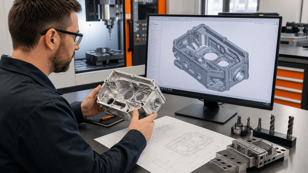
3D CAD Model and 2D Drawing
The 3D model defines nominal geometry and helps with tool-access and setup planning. A 2D drawing should define the requirements that are not safely inferred from CAD, including datums, geometric controls, thread callouts, surface texture, edge conditions, notes and acceptance criteria.
Avoid maintaining conflicting revisions. The quote and purchase order should identify which model and drawing revision controls production. If model-based definition is used, state which embedded annotations are authoritative.
Material, Condition and Stock Form
Specify the material grade and any required temper, heat treatment, certification or directional property. “Aluminum” is not a complete material definition. Different alloys and conditions respond differently to cutting, clamping, residual stress, finishing and service loads.
Stock form also matters. Plate, bar, extrusion, casting and forging can create different machining allowances, grain orientation, residual stress and minimum-order constraints. Our manufacturing materials guide provides an overview, but the final selection should connect performance requirements to a realistic supply condition.
Quantity and Repeat Demand
One prototype and a repeat order of hundreds may use different fixtures, inspection plans and process sequences. State the first order quantity, expected annual demand and whether the design is still changing. This allows the supplier to separate one-time engineering from repeat production planning.
Inspection and Documentation
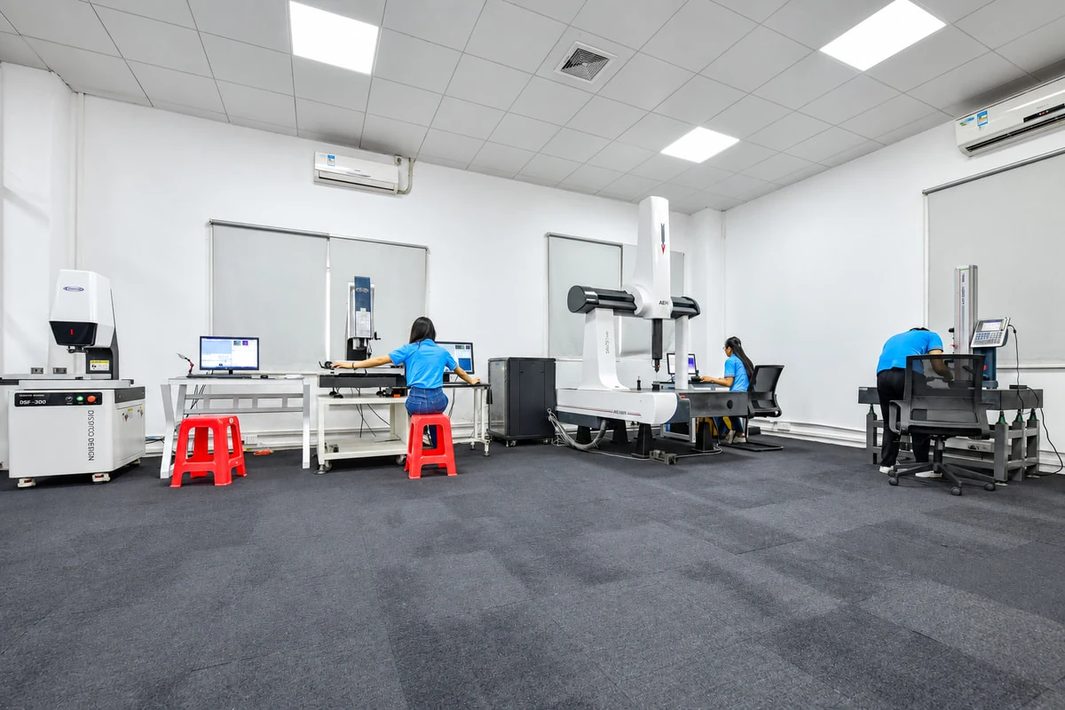
Identify critical characteristics and required evidence before quotation. Requirements may include material certificates, finish certificates, first-off measurements, a dimensional report, CMM results or customer-specific inspection forms. Our CNC machining inspection guide explains how to connect each characteristic to suitable evidence.
Select the Manufacturing Route Before Optimizing the Geometry
The same component can sometimes be produced by three-axis milling, multi-axis milling, turning with live tooling, mill-turn machining, electrical discharge machining or a sequence of processes. DFM should evaluate the likely route before prescribing local geometry changes.
Milling, Turning and Multi-Axis Access
Prismatic housings, plates and brackets commonly suit CNC milling. Rotational parts often favor turning, although cross holes, flats and off-axis features can introduce live tooling or secondary setups. Complex angled features may justify 5-axis CNC machining when it improves access, reduces repositioning or protects datum relationships.
Five-axis machining is not automatically the least expensive route. A simpler machine with a well-planned fixture may be more efficient for stable repeat production. The decision depends on geometry, tolerance relationships, quantity and available equipment.
Process Changes Versus Feature Changes
Some geometry cannot be made efficiently with a rotating end mill. Sharp internal features, narrow slots or difficult access may require EDM, broaching, a formed tool or a design change. DFM should present these alternatives with their effects on cost, lead time and performance rather than treating one rule as universal.
Material and Stock Form Affect Manufacturability
Material choice influences cutting forces, tool wear, heat generation, burr behavior and distortion. It also influences how thin sections, deep pockets and fine finishes behave during machining.
Stable geometry begins with realistic stock. A large housing machined from plate may release residual stress as material is removed. An extrusion may reduce material waste but introduce profile tolerances and grain direction. A casting can approach net shape but may require draft, machining allowance and a different inspection strategy.
If aluminum 6061 is selected for a close-tolerance component, review the relationship between material condition, feature size, setup and measurement in our 6061 aluminum machining tolerance guide. Do not assume one advertised tolerance applies to every feature or part size.
Build a Functional Datum and Tolerance Strategy
Tolerances should communicate assembly function, not express a general preference for precision. A blanket tight tolerance applied to every dimension increases programming, tooling, setup, stabilization and inspection work without showing which features are truly critical.
Choose Datums That Represent Assembly
Primary, secondary and tertiary datums should establish the relationships that matter in use. A broad mounting surface, locating bore and clocking feature may form a functional datum reference frame. The manufacturing team can then plan setups and inspection around that structure.
Avoid choosing a small, flexible or unfinished surface as the primary datum unless it represents the real assembly condition. If a part is flexible, define whether it is inspected free-state, restrained or assembled.
Apply Controls to Functional Characteristics
Use size, position, profile, orientation, runout and surface texture where they communicate a real requirement. Do not add geometric controls only to make a drawing appear complete. Each callout should have a functional reason and a practical verification method.
The ASME Y14.5 standard provides an authoritative system for dimensioning and tolerancing. It supports uniform communication of design intent, but correct symbols alone do not replace engineering judgment about function, datum selection or inspection.
Avoid False Precision
The number of decimal places should match the intended requirement. Extra digits can imply a tighter acceptance range than the design needs. Define general tolerances clearly, then identify exceptions for functional characteristics.
Review CNC Tool Access and Internal Corners
A rotating cutter needs a path to enter, cut and exit the feature. Tool access affects cutter diameter, flute length, holder clearance, rigidity, chip evacuation and achievable surface quality.
Internal Corner Radius
An end mill leaves a radius in an internal corner. Smaller radii generally require smaller cutters, which can reduce rigidity and increase toolpath length. Deep corners may need long-reach tools, increasing deflection risk. Our guide to the internal radius in milling explains why corner geometry should be reviewed with depth and cutter access.
Use the largest internal radius that preserves assembly function. Where a square mating component must fit, consider a relief feature or local alternative rather than making every internal corner sharp.
Tool and Holder Clearance
The cutting edge may reach a surface while the tool holder collides with an adjacent wall. Include surrounding geometry in the access review, especially near bosses, deep cavities and angled faces. The cutting tools guide describes how cutter form, reach and rigidity affect machining strategy.
Design Pockets, Slots and Deep Features with Rigidity in Mind
Pocket depth alone does not determine difficulty. The combination of depth, width, corner radius, opening, wall height, required finish and tolerance controls the risk.
A deep, narrow pocket can require a long tool with limited chip space. This can increase vibration, tool deflection and recutting. A broader opening, larger corner radius, stepped depth or access from another side may provide a better process. If the geometry cannot change, the quote should reflect the required tooling, conservative cutting conditions and inspection plan.
Avoid specifying a fine surface texture at the bottom of a deep pocket unless it serves a function. If only a sealing land or bearing surface needs a controlled finish, identify that local region on the drawing.
Thin Walls and Floors Require a Connected Plan
Thin sections can move under clamp force and cutting force, then spring back after release. Removing material can also redistribute residual stress. Therefore, no single minimum wall thickness can represent every material, height, span or tolerance.
Review:
- Wall height, length and unsupported span
- Material, temper and stock condition
- Cutter engagement and access
- Local support and clamp location
- Roughing and finishing sequence
- Heat treatment or finishing after machining
- Free-state versus restrained inspection
The practical response may include temporary ribs, sacrificial tabs, staged roughing, symmetric material removal, custom support or a modified datum plan. Our thin-wall CNC machining guide covers these interactions in detail.
Specify Holes, Threads and Edge Conditions Completely
Holes and threads combine tool access, depth, chip control, parent material and inspection. A nominal diameter by itself may not define what production needs.
Holes
Identify diameter, depth, through or blind condition, positional relationship and any counterbore, countersink or spotface. Consider whether the drill can enter square to the surface and whether breakthrough creates a burr in an inaccessible area.
Very deep or small holes may require specialized drilling, peck cycles, coolant delivery or an alternative process. The practical limit depends on diameter, depth, material, straightness, surface requirement and equipment.
Threads
Provide the complete thread designation, class or tolerance, depth and entrance condition. Distinguish full thread depth from drill depth in blind holes. Allow room for tool runout and chip accumulation, or use a through hole when the assembly permits it.
Threads near a free edge or thin wall need enough parent material for machining and service loads. Tapping, thread milling and inserts each have different access and production considerations. See our CNC threads and tapped holes guide for method selection and inspection planning.
Edge Breaks and Burr Control
Do not rely on vague notes such as “break all sharp edges” when a functional or cosmetic edge needs a specific result. Define critical chamfers, radii and protected edges. For noncritical edges, a clear general deburr requirement may be appropriate.
Plan Setups, Workholding and Datum Transfer
Every setup introduces locating, clamping and access decisions. Multiple setups are not automatically a problem, but critical relationships across setups require deliberate datum transfer.
Workholding Is Part of the Manufacturing Model
The fixture must locate the part repeatably, resist cutting forces and preserve access. Clamps should not cover critical features or distort flexible surfaces. Soft jaws, nests, vacuum fixtures, modular systems and custom fixtures each suit different geometries and quantities.
Autodesk’s official manufacturing guidance demonstrates the value of representing workholding in the manufacturing model, allowing toolpaths to be planned around the vise and fixture. The broader principle applies across CAM systems: fixture geometry should be treated as part of collision and access planning.
Our article on CNC fixturing and low-volume setup costs explains why setup design, repeatability and quantity must be evaluated together.
Provide Locating Features When Possible
A stable base, accessible locating bore or repeatable edge can simplify setup and inspection. If all external surfaces are highly cosmetic or tightly controlled, the manufacturing team may need sacrificial stock, soft jaws or temporary features. Discuss which surfaces can be used for holding before freezing the design.
Specify Surface Texture and Finishing by Function
Machining marks, roughness, lay and waviness are different aspects of surface texture. The ASME B46.1 standard defines terminology and measurement concepts for surface texture. A drawing should identify the characteristic and limit that matters rather than relying only on terms such as “smooth.”
Surface requirements influence toolpath, step-over, feed, cutter condition and inspection. Apply them to functional areas. A seal, bearing seat or optical interface may justify a controlled texture, while an internal clearance face may not.
Post-machining processes can change dimensions, edges and appearance. Anodizing, plating, passivation, bead blasting, polishing and coating should be considered before final tolerance decisions. Review the available CNC machining surface finish options and state which surfaces must be masked or protected.
Quantity and Repeatability Change the DFM Decision
A prototype may use general-purpose workholding and more manual inspection. Repeat production can justify dedicated jaws, fixtures, preset tools, in-process probing and controlled sampling. The geometry has not changed, but the economically sensible process can change.
State whether the order is:
- A concept prototype for fit and learning
- A functional prototype with controlled characteristics
- A low-volume bridge order
- A repeat production part
- A spare or replacement part with uncertain future demand
This context helps the supplier explain one-time setup and whether a design change will matter only for one order or throughout the product lifecycle.
A Practical CNC DFM Review Workflow
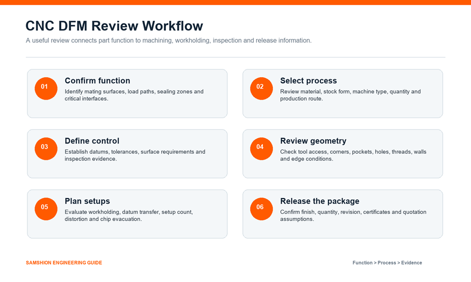
- Confirm function. Identify mating surfaces, load paths, sealing zones, critical interfaces and cosmetic requirements.
- Select the likely process. Review material, stock form, machine type, quantity and secondary operations.
- Define control. Establish functional datums, tolerances, surface requirements and inspection evidence.
- Review geometry. Check tool access, corners, pockets, walls, holes, threads and edge conditions.
- Plan setups. Evaluate workholding, datum transfer, setup count, distortion and chip evacuation.
- Release the package. Confirm finish, quantity, revision, certificates and quotation assumptions.
This sequence prevents isolated changes. For example, enlarging a radius may help cutting but affect fit. Changing the datum may simplify inspection but complicate workholding. A connected review shows those tradeoffs before production.
How DFM Can Reduce CNC Machining Cost
DFM reduces cost when it removes work that does not protect function. Savings should not be promised as a universal percentage because the effect depends on the original design, quantity and production route.
Common cost drivers include:
- Additional setups or repositioning
- Long-reach or very small cutting tools
- Slow machining of deep, narrow features
- Tight tolerances on nonfunctional dimensions
- Fine surface requirements over large areas
- Special inspection or complete reporting
- Dedicated workholding for difficult access
- Secondary finishing, masking and reinspection
The most effective change is often not a minor dimension edit. It may be relocating a feature so it can be machined in the primary setup, relaxing a nonfunctional requirement, clarifying a datum or changing the stock form. DFM should compare the design effect and production effect together.
CNC DFM Design Risk Checklist
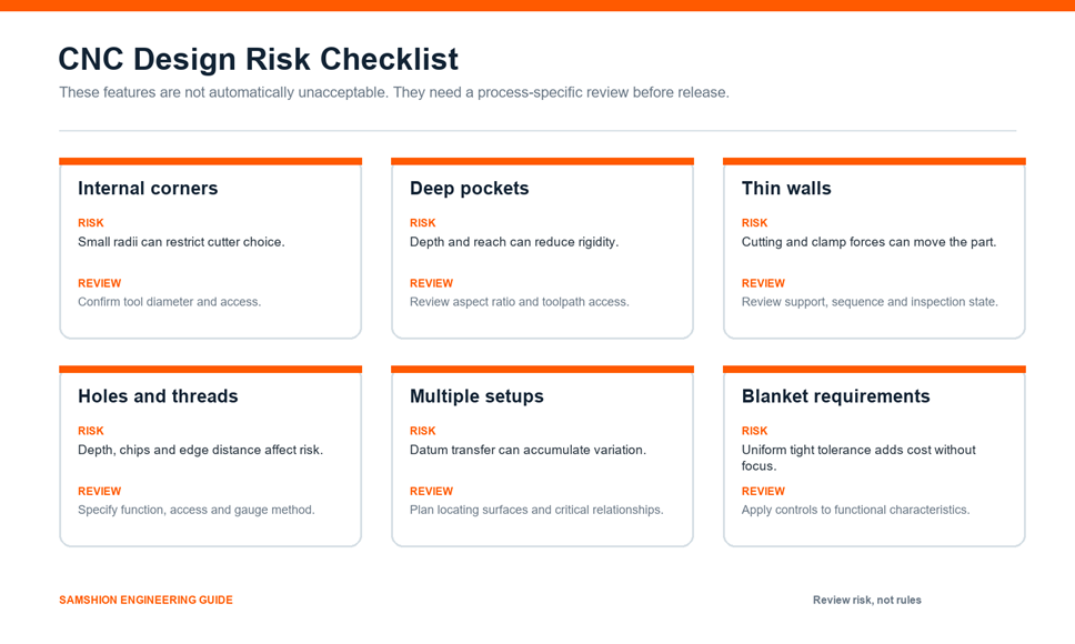
- Are functional surfaces and critical relationships identified?
- Does the datum structure represent assembly and inspection?
- Can cutters and holders reach every machined feature?
- Are internal radii compatible with feature depth and function?
- Do deep pockets have adequate opening, rigidity and chip access?
- Have thin walls and floors been reviewed for support and distortion?
- Are hole and thread specifications complete?
- Can the part be held without blocking access or bending critical surfaces?
- Are cross-setup relationships controlled by a practical datum-transfer plan?
- Are tight tolerances limited to functional characteristics?
- Are surface requirements assigned only where needed?
- Are finish, masking, certificates and inspection reports defined?
- Are quantity and repeat demand included in the manufacturing decision?
What Samshion DFM Feedback Should Contain
A useful DFM response should be specific enough for the designer to make a decision. It may include:
- The feature and drawing requirement under review
- The manufacturing or inspection risk
- The reason the risk occurs
- A recommended change or alternative process
- The likely effect on function, cost, lead time or evidence
- Any assumption that needs customer confirmation
The review should not promise a fixed saving or response time unless it is supported by the actual quotation and project scope. Some parts need only a short clarification. Others require a detailed setup, tolerance or finishing discussion.
Upload the controlled CAD model and drawing, then identify material, quantity, finish, critical characteristics and required documentation. Samshion can review the design against machining, workholding and inspection needs before production. Request a CNC machining quote.
Frequently Asked Questions
What is design for manufacturability in CNC machining?
It is a review that connects part function to a practical manufacturing and verification plan. It covers process selection, material, tool access, internal corners, walls, holes, threads, workholding, datums, tolerances, finishes and inspection.
Is there a universal minimum wall thickness for CNC parts?
No. Manufacturability depends on material, wall height and span, surrounding geometry, cutting access, support, sequence, tolerance and inspection state. A thin section may be feasible with the right process, but it needs a part-specific review.
What internal corner radius should I use?
Use the largest radius that preserves function and assembly. The practical choice depends on pocket depth, cutter access, holder clearance, material and finish. If a square mating part must fit, consider a relief feature or another local solution.
Should every CNC dimension have a tight tolerance?
No. Tight controls should protect fit, alignment, sealing, motion, load transfer or another defined function. General dimensions can use an appropriate general tolerance while critical characteristics receive specific controls.
Does five-axis machining eliminate all DFM restrictions?
No. Five-axis equipment can improve access and reduce repositioning, but tool reach, holder clearance, workholding, collision risk, material behavior and inspection still matter. It is one process option, not a substitute for design review.
What files should I send for a CNC DFM review?
Send the controlled 3D CAD model and 2D drawing, plus material and condition, quantity, finish, critical characteristics, assembly context and required certificates or inspection reports.