CNC prototype design changes do not always require a new part. An existing component may be modified when it has sufficient material, can be located and machined again, and can meet the revised drawing without compromising other requirements. If the completed modification would leave features or a structure that differ from the new drawing, making a replacement is the appropriate recommendation.
At SAMSHION, we evaluate the existing part before deciding on the route. Our main checks are the available material, the feasibility of reclamping and machining, and the effect on other critical dimensions, fits and surfaces. We modify the original part when the assessment supports it. When it cannot be brought into agreement with the revised design, we advise the customer to have it machined again.
For a buyer, the useful question is therefore not simply whether another cut is possible. It is whether the part left after that cut will be the component the new drawing requires. This guide explains how to assess that question and what to clarify before authorizing a modification.
Start with the revised part rather than the proposed cut
In this guide, CNC part rework means additional machining of an existing component following a design change. It does not imply that the original part was defective. A part can conform to an earlier revision and still be unsuitable for a later one.
Compare the revised design with the actual condition of the component. Identify features that become larger, smaller, deeper or differently positioned, as well as features that must disappear. Include changes to datums, tolerances and finish requirements even when the visible model shape looks unchanged.
A useful initial decision can be organized around the following checks.
Passing one check does not replace the others. A pocket may have enough material for widening but be impossible to hold securely in its finished condition. A hole may be accessible while its proposed new position leaves part of the previous opening behind.
Check material where the revised feature needs it
Remaining machining allowance is local. A component may still have a thick base while lacking material at the wall, shoulder or bore that needs to change. Overall weight and the original stock size do not answer whether the revised geometry is present.
For a change that removes more material, inspect the surrounding structure as well as the target surface. A deeper pocket reduces the material beneath its floor. A wider slot changes the material on either side. Removing a face can alter the distance from that face to holes or shoulders that were acceptable under the previous revision.
The opposite direction is more restrictive. Further cutting cannot make an existing bore smaller or restore a wall that has already been machined too thin for the revised design. Welding, plugging, inserts or bonded additions are separate design and process proposals. They should not be treated as equivalent to a one-piece component without explicit engineering approval and a suitable acceptance plan.
The practical review should also consider the measured condition of a completed part. A nominal CAD comparison can suggest that material remains, but the actual dimension may be near a tolerance limit. A thin margin on the screen is not a reliable machining allowance until the relevant geometry and process have been assessed.
Evaluate hole changes in their full geometric context
Increasing a bore diameter
Enlarging an existing bore can be a candidate for modification if the revised bore fits within the remaining material. Check the required axis, usable length, shoulder depth and nearby wall thickness. A larger opening can affect a mating component even when its new diameter is correct.
The machining method depends on access and the required result. Boring, milling or another suitable operation may be considered, but an existing hole does not automatically provide a correct reference. Our hole tolerance machining guide explains why hole size and location need separate consideration.
Moving a hole center
A shifted hole needs a geometric overlap review. Increasing the new diameter does not by itself prove that the old opening will disappear. The previous hole must lie inside the region removed for the revised feature over the relevant depth if the finished part is to have an uninterrupted bore of the new shape.
If some of the old opening extends outside that region, additional milling cannot restore the missing material. Leaving a crescent-shaped opening, an unintended slot or an extra passage may conflict with the revised drawing. The customer would need to approve a different design; otherwise, the part should be remade.
Adding a hole or changing a thread
Adding a hole requires checking its path through the whole component. Review intersections with existing bores, the remaining section beneath a blind hole, the required thread engagement and access for deburring. An accessible entry point does not prove that the complete feature is suitable.
A revised thread should be assessed against the existing hole and thread geometry. It is not enough to compare nominal thread names. The required preparation diameter, thread depth and remaining wall all matter. A thread insert is not an automatic substitute for the revised drawing requirement.
Review pockets slots and external steps separately
Pocket and slot changes often appear straightforward because they involve removing material. The revised width or depth must still preserve adjacent walls, mounting pads and interfaces. A wider pocket can remove part of a threaded boss; a deeper slot can break into a cavity that was previously separate.
The sequence can change too. The original pocket may have been roughed while the stock was stiff and then finished after other operations. Returning to the same region after thin walls have been completed presents a different workholding and cutting problem. The previous toolpath should not be assumed suitable for the new condition.
On turned components, reducing an outside diameter or moving a shoulder may be possible where material remains. Increasing a fitting outside diameter or restoring an already shortened section generally cannot be accomplished by further cutting alone. Review the direction of the change rather than treating every revised step length as the same task.
The examples above are geometric scenarios, not records of a particular SAMSHION rework project. Their purpose is to show why a small drawing change can produce different decisions depending on the material already removed.
Reestablish the locating references before machining
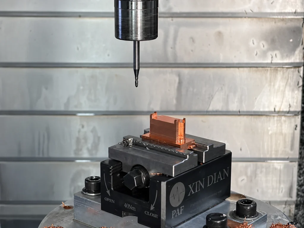
A finished component may no longer have the stock surfaces, tabs or gripping length used for its original setup. Reworking machined parts therefore requires a fresh review of where the component can be located and held. The original fixture may remain useful, need adjustment or be unsuitable for the new operation.
Locating establishes the part’s relationship to the machine; clamping holds it against the cutting loads. A convenient gripping face is not necessarily the reference that controls a revised hole or slot. The setup must preserve the drawing relationships between the modified feature and the features that remain.
For example, a cross-hole located from a fitting diameter and shoulder needs a setup that respects those references. Locating from a different outside step because it is easier to grip can produce a hole that looks correctly placed locally but misses the required relationship. Our guide to datum transfer across CNC setups discusses this issue in more detail.
Tool access must be reviewed with the complete holder and fixture in place. A tool tip may reach a recess while the holder cannot pass an adjacent wall. Extending the tool to clear the obstruction also changes its stiffness. Sandvik Coromant’s boring application guidance identifies tool diameter and overhang as important setup considerations.
Preserve the dimensions and surfaces that did not change
An engineering change to one feature does not remove the requirements on the rest of the part. The assessment should identify which existing dimensions, fits and surfaces could be affected by reclamping, cutting or subsequent finishing.
Clamping can mark a cosmetic face or temporarily distort a flexible section. Chips trapped at a locating contact can shift the setup or damage a finished surface. Cutting near a bore or slot can create burrs that interfere with assembly even when the main revised dimension is acceptable.
These risks do not mean that every finished component must be discarded. They mean that protection and support belong in the modification plan. The CNC part surface protection guide covers contact marks and handling damage as separate concerns from dimensional accuracy.
A dimension change can also affect the tolerance chain. Moving a shoulder changes an axial locating relationship; moving a hole can change edge distance and alignment to a mating component. Review the connected features rather than inspecting only the surface that was visibly machined.
Where fit is the reason for the revision, share the relevant mating-part information. A trial assembly can provide useful additional evidence, but it should not be used to replace dimensional requirements or accept an unintended structural difference. Our prototype assembly checks guide explains how assembly review relates to the customer drawing.
Treat material and surface condition as part of the revision
Some revisions change the specification without adding a new pocket or hole. A different material grade, heat-treatment condition or surface requirement can make an existing component unsuitable even when the geometry could be modified.
Further machining does not change the underlying alloy into a newly specified grade. Likewise, an already treated component may require a different cutting and finishing route from untreated stock. Review the required final condition instead of assuming that a visually similar part is an acceptable substitute.
If the part has been coated or plated, an additional cut can expose the base material and change the condition of nearby edges. Reapplying a finish may affect dimensions or appearance. Whether stripping, remachining and refinishing are appropriate depends on the material, process and drawing requirements; they should not be promised as a routine solution.
Confirm the drawing revision and the scope of authorization
Before a modification is authorized, the customer and supplier should agree on the definition of the revised component. A marked image can help communicate a request, but it may not define tolerances, depths, datum relationships or the surfaces that must remain unchanged.
Provide the updated drawing and model where available, identify the revision, and highlight what changed. If a drawing and model conflict, resolve the discrepancy rather than allowing the machinist to guess. An instruction to enlarge a hole also needs its final size, position and any related acceptance requirements.
Drawing revision control should connect the design change to the manufacturing instructions and inspection requirements. Autodesk’s change order documentation describes how changes can be tracked against designs and drawings. A formal software platform is not the subject of this guide; the important point for the job is that everyone acts on the same approved definition.
Also distinguish a modification proposal from permission to proceed. If the suggested route leaves an extra opening, changes a visible surface or uses an inserted feature, the customer needs to understand that difference. A component accepted as a special deviation should not be described as fully conforming to an unchanged drawing.
Compare rework and remake using the work still required
The cost already spent on a prototype does not establish which route is better now. Compare the additional work, the likelihood of achieving the revised result and the consequences if the existing part cannot be recovered.
Rework may avoid new stock preparation and machining of features that remain suitable. It can still require model comparison, revised programming, fixture preparation, setup verification and inspection. These tasks can dominate a small modification. Our CNC fixturing and setup cost guide explains why the number of cuts alone is a poor measure of manufacturing effort.
A remake may repeat more machining, but it can allow a normal sequence from suitable stock rather than a difficult setup on a finished component. Neither route is automatically cheaper or faster. Compare the complete scope, including any return shipping and finishing that apply to the order.
An urgent exhibition or assembly deadline does not make an incompatible structure acceptable. Confirm what the prototype must demonstrate and the condition in which it will be used. A modified demonstration model should not be assumed suitable for tests that require the final production configuration. Our rapid CNC prototyping timeline guide provides context for scheduling the remaining manufacturing steps.
Verify the revised feature and its affected relationships
CNC prototype inspection after modification should address the revised requirement and the features that the modification could disturb. Agree on the inspection scope before proceeding, especially when only some parts of a batch are being changed.
For a revised bore, size verification alone may not establish its position or relationship to the locating outside diameter. For a deeper pocket, the remaining floor thickness may matter alongside depth. For a moved shoulder, the distances to adjacent features and the resulting assembly position need attention.
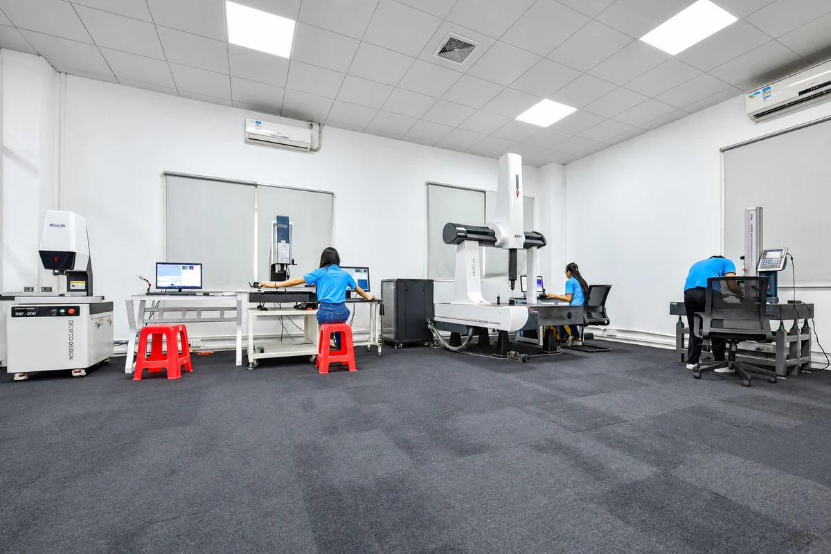
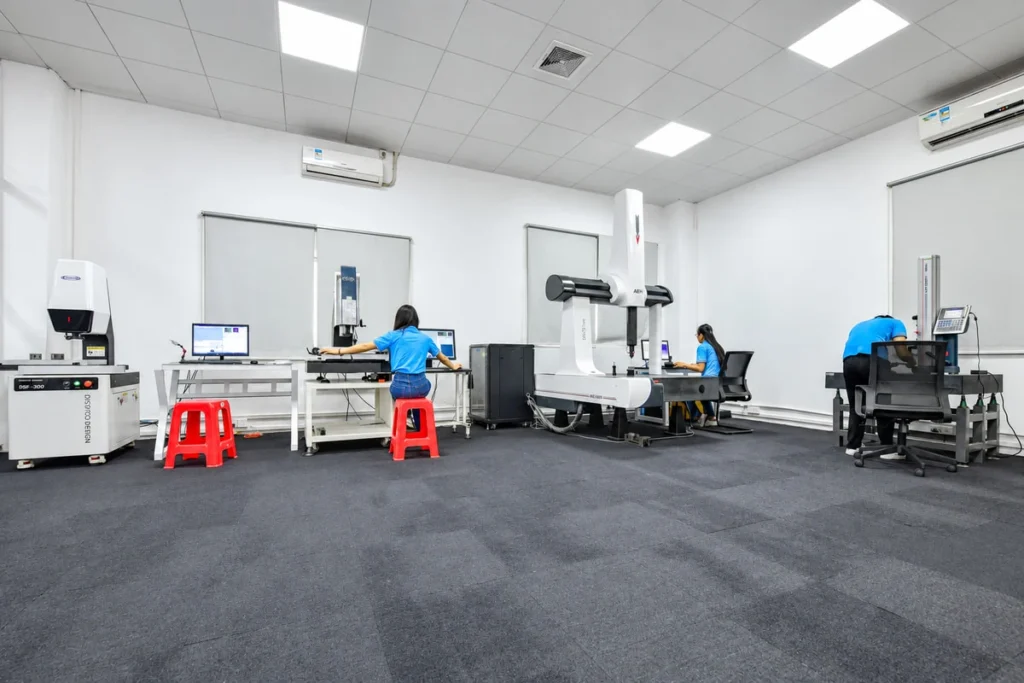
Select the inspection method to suit the characteristic and access. A gauge check, a micrometer reading and a datum-based CMM measurement answer different questions. Do not assume an earlier report covers the revised geometry, or reuse an old acceptance result for a surface that has since been machined.
Inspection records should make the applicable revision clear and identify the relevant part or lot. Distinguish characteristics measured again from results carried forward under an agreed plan. Our guide to CNC inspection reports explains the different purposes of dimensional reports and supporting documents.
Information to send for a modification assessment
A useful enquiry allows the manufacturer to compare the requested result with the component that actually exists. Include the following where applicable.
- The original part number and revision, together with the proposed new revision.
- The revised drawing and 3D model, with the changed features identified.
- The quantity already machined and the number that need modification.
- The current manufacturing stage and whether the parts have been delivered.
- Material and treatment information, plus the existing surface condition.
- Critical dimensions, fits and cosmetic surfaces that must be preserved.
- Available inspection results and photographs showing the present condition.
- Mating-part information if assembly fit is driving the change.
- Required inspection records and the date by which the modified parts are needed.
Photographs help show access, finish and obvious structural differences. They do not establish a precision allowance or replace an inspection of a critical feature. If the assessment depends on actual size, make that measurement part of the review rather than estimating it from the image.
Common questions about CNC prototype modifications
Can a larger hole always be machined in the original part
No. The revised diameter must be considered with its axis, depth, surrounding material and fit requirements. If the center moves, the previous opening may remain partly outside the revised bore. The final geometry must be assessed, not only the increase in diameter.
Does an old hole matter if it will not be used
It can. An extra hole may change the structure, appearance, sealing boundary or relationship to other features. If the new drawing does not permit it, leaving it in place is a design difference that needs customer approval. It should not silently be accepted as an exact match to the new revision.
Is modifying a finished prototype always faster than remaking it
No. Reclamping, revised programming, surface protection and inspection can outweigh the machining saved. If parts have been delivered, return shipping can also affect the schedule. Compare the work still required for each route before choosing.
Can a design change be applied to only part of a batch
It may be possible, but identify which pieces will carry each revision and keep their records distinguishable. The revised machining and inspection requirements must apply to the correct pieces. Avoid shipping a mixed set without the customer’s agreement on the required configuration.
Why recommend a remake when there is still material left
Material remaining somewhere on the part is not sufficient. It must be present where the revised feature needs it, the component must be practical to machine again, and the finished structure must match the new drawing. At SAMSHION, an incompatible final feature or structure is a reason to recommend machining a replacement.
Request a review before deciding to modify or remake
Send the current part information and proposed revision to SAMSHION for a machining review. Identify the changed features and the dimensions or surfaces that must remain untouched. We can assess whether the original component has enough material and can be machined again without compromising those requirements, or whether the revised design calls for a new part.