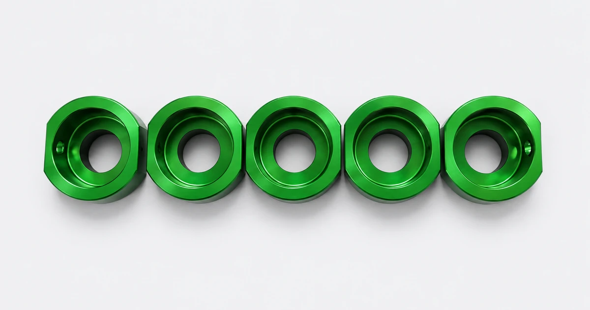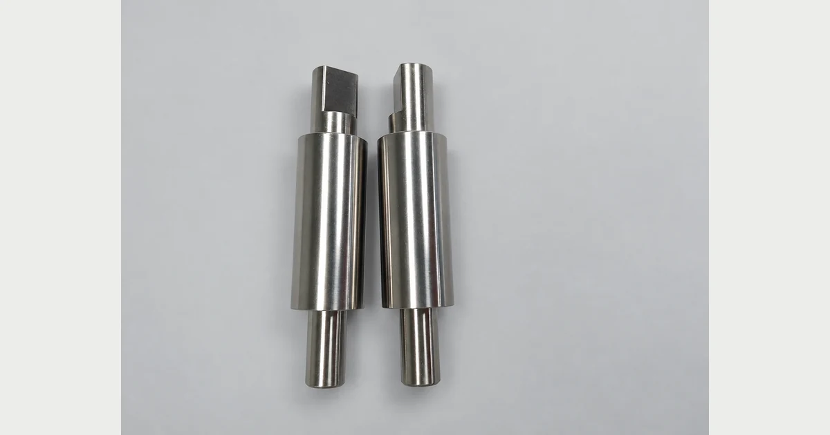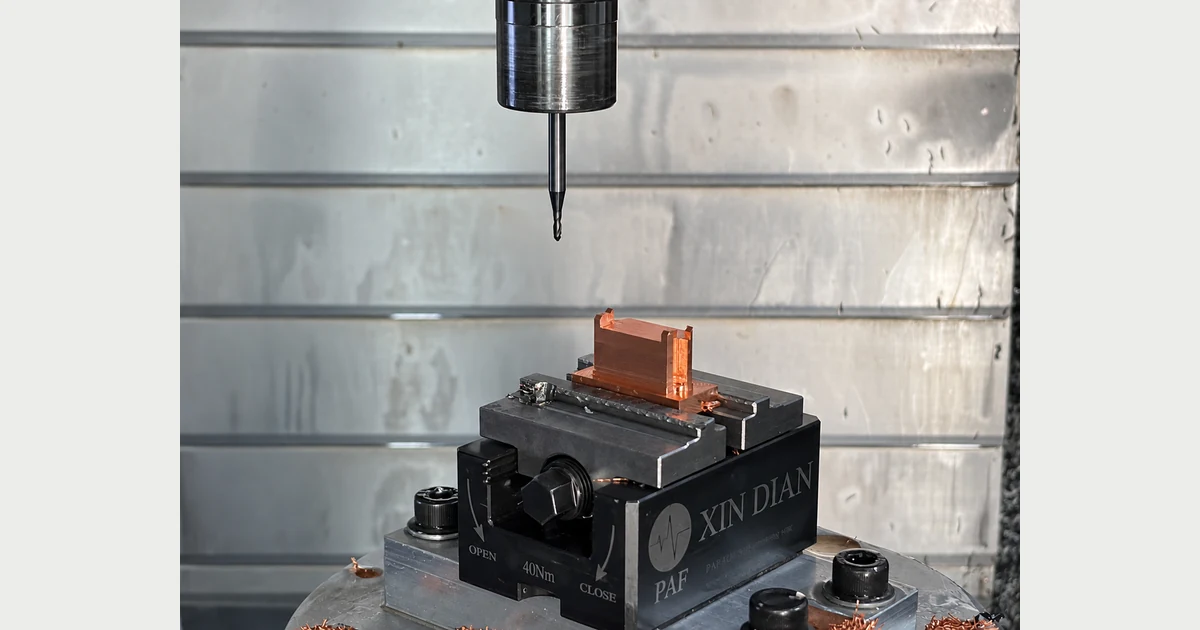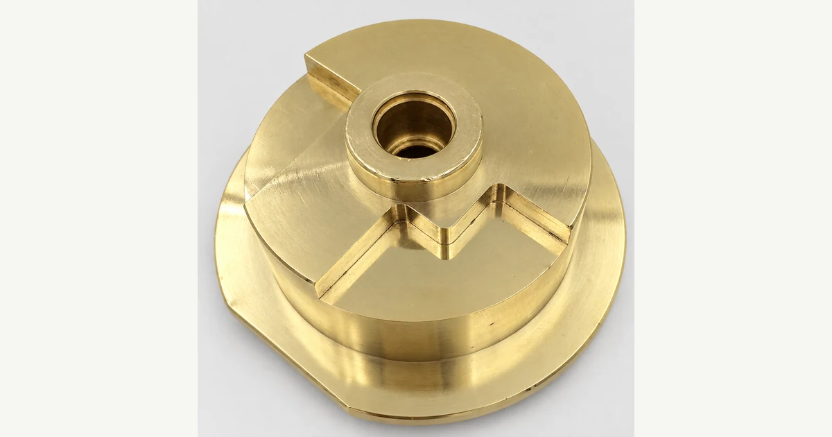
CNC part surface protection begins before a finished component reaches its shipping carton. A clamp can leave an impression, a trapped chip can score a locating face, and two acceptable parts can scratch each other during transfer. The response depends on where the mark is, what the surface does, and the appearance requirements agreed with the customer. A visible line is not automatically a reject, but an acceptable diameter does not automatically make surface damage acceptable.
At SAMSHION, we have encountered clamping impressions and surface scratches on machined brass components. Our measures include protective pads, control of clamping pressure, separate placement of parts and protective material between components. For appearance assessment, we first make an internal preliminary judgment, then evaluate the condition against the customer’s drawing, sample or reference images. This guide connects those practical measures with workholding, inspection and packaging decisions for custom machined parts.
Identify the surfaces that need protection
A drawing should distinguish an exposed appearance face from a surface that controls assembly. A visible outer panel may need a consistent appearance. A bore, sealing land or mounting face may need protection because a local defect affects contact or fit, even when the area cannot be seen after installation. Some surfaces perform both functions.
Mark these areas before deciding where a clamp can touch. A convenient flat surface is not necessarily an unrestricted clamping face. Likewise, a region hidden inside an assembly is not automatically suitable for dents or deep scratches. Its function determines which requirements still apply.
For a turned and milled part, review the cylindrical seats, shoulders, milled faces and edges individually. A contact mark on a clearance band may have a different consequence from a mark on a locating diameter. If machining stock will later be removed from a gripping area, that allowance belongs in the process plan rather than being assumed after damage occurs.
Our brass CNC machining guide gives the material and feature context for the product examples used here. The protection principles also need a job-specific review for other materials, geometries and finishing routes.
Distinguish tool marks from surface damage
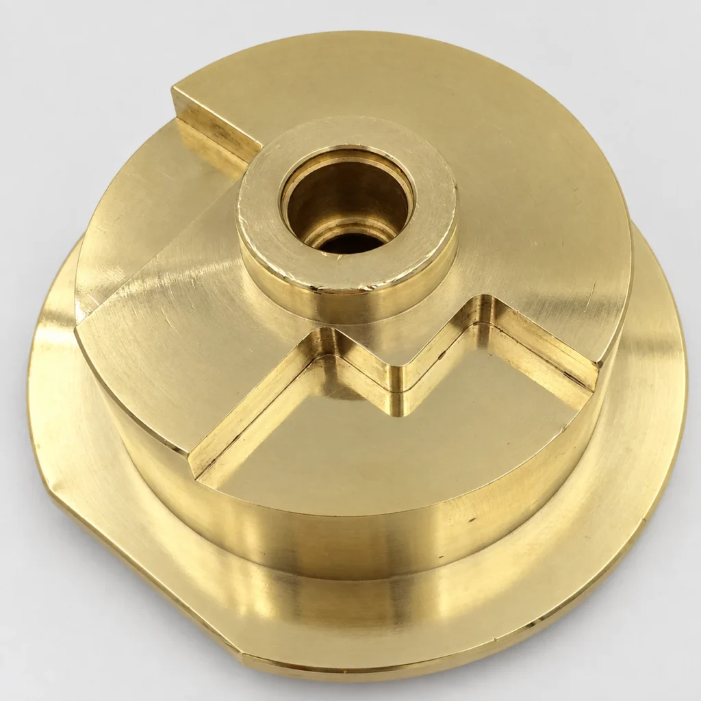
An as-machined surface normally reflects the cutting process. Turning can leave circumferential feed lines, while milling can leave overlapping paths. These patterns can be visible on a part that meets its requirements. Their presence alone does not establish a scratch, a roughness failure or an appearance defect.
A clamping impression is associated with contact loading. Jaw texture, concentrated pressure or a particle trapped at the contact can leave a local witness. A handling scratch can result from relative movement against an edge, chip or another hard surface. An impact can create a dent with displaced material. Similar-looking marks can have different origins, so location and process history matter alongside appearance.
Use the observed condition to guide the investigation, not to declare the cause from a photograph alone. Check where the fixture contacts the part, whether the surface was already finished, and at which transfer or inspection the mark became visible. An elongated mark near a jaw is a useful clue, but it does not prove which operation produced it.
Differentiate identification from disposition. The first task is to describe the condition accurately. The next is to decide whether it meets the actual requirement and what further checks are needed.
Keep appearance roughness and dimensions separate
Surface roughness, cosmetic appearance and dimensional conformity are related, but they are not interchangeable. A surface can meet a specified roughness value yet contain an isolated mark outside the measured trace. Conversely, a consistent machining pattern can remain visible while meeting both the roughness requirement and the agreed appearance condition.
Ra describes an average property of a measured roughness profile. It is not a universal scratch-depth limit or a complete inspection of every point on a face. KEYENCE’s explanation of arithmetic mean roughness helps explain the distinction. A local defect needs a method that can evaluate the characteristic actually in question.
A CMM report also has a defined scope. It can contain results for dimensions and geometric relationships, but a passing report does not automatically certify the absence of scratches, dents or handling marks. A feature can pass its reported size check while requiring a separate appearance or surface-condition decision.
For a functional surface, ask whether the mark affects seating, fit, sealing or the specified texture. For a cosmetic surface, compare it with the designated appearance requirement. Where both apply, both need to be satisfied. Our surface roughness and dimensional tolerance guide develops this distinction in more detail.
Prevent clamping marks without losing workholding stability
The objective is to hold the part securely while avoiding unacceptable contact damage. At SAMSHION, protective pads and pressure control are measures we use for this purpose. They must work as part of the complete setup, including the gripping location, support, cutting forces and access.
A protective pad changes the contact interface. Its thickness, stiffness and condition can affect how the component sits and how the load is distributed. A layer that protects the appearance but allows movement or changes a critical reference is not a suitable solution. The pad material and arrangement should be selected for the particular setup rather than copied from a visually similar part.
Clean contact is important. A small chip trapped between a pad and the component can concentrate the load and leave a mark. Reusing a protective layer without checking its surface can carry debris into the next loading. Inspect the part contacts and support surfaces as well as the padding itself.
Avoid choosing the lowest possible pressure as the only control. Insufficient holding can allow slip, vibration or a change in position during cutting. Excessive pressure can leave impressions or distort a flexible section. Assess a secure arrangement that protects the required faces, then verify the part in the condition required for acceptance.
Carr Lane’s fixture design guidance makes the same basic connection between adequate holding and avoiding significant surface damage. Our CNC fixturing and setup guide explains the wider planning and cost implications of workholding choices.
Plan contact locations across repeated setups
A part may need to be turned, milled, deburred and measured before it is finished. Each transfer introduces another opportunity to contact an already controlled surface. Planning protection only for the first operation leaves those later contacts unresolved.
Where the geometry permits, place gripping contacts on material that will be removed or on an agreed noncritical region. Other jobs may justify shaped jaws, additional support or a different operation sequence. These are possible engineering choices, not a claim that one fixture style is used on every SAMSHION part.
Preserve the locating reference when adding protection. A variable or compressible layer under a datum face can change the position established by the fixture. Chips, burrs and inconsistent seating can produce a similar problem. Check both surface protection and repeatable location after a setup change.
For components with features on several sides, carry the functional references through the operation sequence. Our datum transfer guide explains why an individually correct hole or face can still be misplaced relative to the rest of the part. Protective measures should support that relationship rather than obscure it.
Loading and unloading deserve attention as well. Lift a part clear of a contact instead of sliding a finished face across a jaw or tray. Confirm that the chosen approach is practical for the component’s size and weight. A well-protected machining operation can still be followed by an avoidable handling scratch.
Separate parts between operations and during storage
Preventing scratches on machined parts continues after unclamping. At SAMSHION, we separate components and use protective material to reduce part-to-part contact. An edge, projecting feature or corner on one component can damage the broad face of another if the parts are allowed to rub together.
The separation needs to remain effective when a tray is moved. Merely placing components apart on a bench does not prevent them from sliding together during transfer. Consider their shape, orientation and the way they are supported. Thin webs, long extensions and sharp changes in section can need protection from load as well as abrasion.
Keep loose chips away from the protection system. Wrapping a component together with debris can trap an abrasive particle against the surface. Protective material should also be suitable for the surface condition and any remaining process residue. A clean barrier is different from a contaminated piece of material that happens to feel soft.
Use protection that can be removed without creating a new problem. Adhesive films, caps and other special methods may be useful on suitable jobs, but they need a compatibility review. Do not assume that a particular adhesive leaves no residue or that the same packaging material suits every coating, metal and plastic.
Protect surfaces during inspection and edge work
Inspection adds contact points through measurement tables, supports, gauges and handling. Arrange the part so a controlled face is not dragged across the platform while another feature is checked. Supports must still establish the measurement condition correctly; surface protection cannot justify an unstable or inappropriate alignment.
Select the inspection method for the requirement. A visual review can identify an appearance concern, while a dimensional or surface measurement may be needed to characterize its functional consequence. Avoid applying a convenient instrument to a question it cannot answer. The CNC machining inspection guide explains how instrument choice and reporting scope should follow the controlled characteristic.
Deburring and local edge work also require defined limits. An abrasive tool can remove a burr and unintentionally change a nearby appearance face, corner or mating edge. Protect adjacent areas and maintain the drawing’s edge condition rather than blending everything until the component looks uniformly smooth.
If a scratch intersects a bore entry or mounting face, review both the local edge and the relevant fit. A small raised lip can matter differently from a shallow mark on a broad clearance face. Our deburring and edge inspection guide provides the related feature-level considerations.
Agree on cosmetic inspection criteria before production
At SAMSHION, our appearance assessment begins with an internal preliminary judgment. We then evaluate the condition using the customer’s drawing, sample or reference images. That internal assessment helps identify a concern; it does not replace the customer’s specified acceptance requirement.
The references need to describe the same surface and delivered condition. A raw machined sample is not automatically an appearance standard for an anodized part. A small reference image of one face may not establish the permitted condition on another. Identify the relevant drawing revision and which sample or image is intended to guide acceptance.
For repeatable cosmetic inspection of CNC parts, the buyer and supplier should agree on the significant surfaces and how they will be viewed. Lighting, viewing direction, distance, magnification and cleanliness can change which marks are visible. Specify these where they affect the decision; there is no single viewing distance or scratch allowance that applies to every custom component.
An approved boundary sample can help communicate the acceptable limit, provided its role and condition are clear. A sample showing a general texture should not silently become permission for unrelated dents or deep scores. Where a written requirement and sample appear inconsistent, clarify the intended acceptance basis instead of choosing whichever is easier to satisfy.
If a condition remains ambiguous, describe it and seek clarification before deciding on rework or release. A useful discussion identifies the surface, observed mark, relevant requirement and possible effect on function. Asking only whether a photograph looks acceptable leaves too much room for different interpretations.
Use photographs to document the condition accurately
Photographs are useful for showing where a mark is and for discussing appearance with a customer. Include an overall view so the location is clear, then a closer view that shows the condition. Keep orientation and lighting reasonably consistent when comparing a questioned part with a reference.
A reflection can hide a scratch in one view and emphasize it in another. A picture should therefore support the review rather than substitute for a necessary measurement or physical examination. Avoid assigning scratch depth, roughness or the cause of a defect from a normal product photograph.
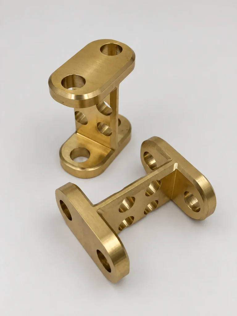
Keep original images when recording a questioned surface. Retouching, smoothing or selective exposure changes can remove evidence or change the apparent severity. Presentation images used in a blog have a different purpose from the original records used for acceptance. The product photographs in this article illustrate machined geometry, not measured defect severity or customer acceptance decisions.
Evaluate rework before removing material
Polishing a visible line can change more than its appearance. Local material removal can affect a diameter, thickness, corner, flatness or surface texture. Blending a small area can also leave a different gloss or tool pattern from the surrounding face. Review the proposed process against the controlled features before starting.
An affected noncosmetic surface still needs a functional assessment. Being out of sight does not waive fit, sealing, coating or dimensional requirements. If a deviation from the agreed requirement is proposed, obtain the appropriate customer disposition rather than treating internal judgment as approval.
For a treated part, removing and renewing the finish may introduce further dimensional or appearance changes. The affected features and final inspection condition need to be reviewed for that job. Our surface finishing services provide context for selecting finishing routes, masking and appearance requirements.
After an approved rework, check the characteristics it could have changed. The scope may include local size, a mating face, texture, edge condition or coating continuity. Repeating an unrelated dimension check does not establish that the repair preserved the required surface.
Match protective packaging to the component
Protective packaging for precision machined parts should preserve separation and support the geometry. A soft outer layer does not prevent damage if components can move inside it or if a heavy part loads a delicate feature. Review the expected contacts, not only the carton size.
Separate finished faces from neighboring edges and prevent movement that can create repeated rubbing. Support the component where it can carry the load without bending a thin section. Avoid making a precision bore, projecting pin or cosmetic edge the unintended stop against which the whole part moves.
Packaging materials need to suit the substrate and finish. Moisture protection, corrosion prevention, cleanliness or special environmental requirements should be defined when relevant. Do not assume that ordinary wrapping provides a specified corrosion life, cleanliness class or transport-test performance.
Consider unpacking too. Protection should be removable without dragging a hard edge over the part or requiring an uncontrolled cut next to a finished face. Where a component needs handling instructions, communicate them with the shipment as agreed. A packaging method should protect the part through removal as well as transit.
Packaging is the final protection step, not a remedy for an unresolved surface condition. Confirm the required condition before packing, then ensure the protection does not create new marks, residue or deformation.
Include surface protection requirements in the RFQ
The quotation and manufacturing review are more useful when the required appearance and functional surfaces are identified together. Send the controlled drawing and CAD model, then include the following where applicable.
- Material grade, condition and required final surface treatment.
- Appearance faces, functional contact areas and any restricted clamp locations.
- Surface texture requirements and their controlled locations.
- The approved sample or reference images and what each reference establishes.
- Permitted marks, designated inspection conditions and any customer appearance specification.
- Requirements for packing separation, protected features and compatible materials.
- The records or customer review needed if an uncertain condition is found.
Identify whether the requirements apply before or after finishing. If a reference image is for visual context only, say so. Likewise, identify whether a physical sample defines color, texture, acceptable marks or several of those characteristics. This makes it easier to plan protection and assess the result on the same basis.
Frequently asked questions about machined surface protection
Are all visible machining lines unacceptable
No. Visible cutting patterns can be part of an acceptable as-machined surface. Acceptance depends on the specified roughness, appearance and functional requirements. A repeating pattern should not automatically be called a scratch, and visibility alone does not establish a failure.
Does a passing CMM report prove that a part is scratch free
No. A CMM report establishes the characteristics and measurement scope actually included in that report. Scratches, dents and cosmetic appearance require their own applicable checks. Correct dimensions and an acceptable surface condition are separate decisions.
Are protective pads enough to prevent clamping marks
They are one measure, not a complete setup. Check contact cleanliness, pad condition, support, gripping location and pressure. A contaminated pad can trap a chip, while an unsuitable layer can reduce positioning stability or allow movement during cutting.
Can a scratch be accepted on a hidden face
Possibly, if it meets all applicable requirements or an appropriate deviation is approved. Hidden surfaces can still control fits, sealing or structural contact. Do not use visibility as the only acceptance rule.
Should scratches always be polished out before shipment
No. Removing material may change dimensions, edges or the finish. Evaluate the requirement and proposed repair first. An unnecessary repair can turn an acceptable surface condition into a dimensional or appearance problem.
Can customer pictures replace an appearance sample
Pictures can support assessment when their purpose and viewing limitations are understood. They do not automatically establish every surface requirement. Where lighting, color, gloss or a boundary condition is critical, agree on suitable references and inspection conditions.
Discuss surface protection before machining begins
CNC part surface protection works best when the appearance requirement, functional surfaces, workholding and handling route are considered together. Protective pads, pressure control and separate placement address practical risks, while clear references provide a consistent basis for judging the finished condition.
Send your drawing, CAD model, quantity and appearance references to SAMSHION for a manufacturing review. Mark the faces that must be protected and identify the final finish and packaging requirements so the quotation can address them from the start.