
Manufacturing Tolerances by Process and Part Requirement
Use practical tolerance guidance to prepare clearer drawings and choose an appropriate manufacturing process. Final acceptance is based on the approved drawing, material, geometry, production route, finishing sequence and agreed inspection method. A universal tolerance claim does not define acceptance.
- Drawing-based tolerance review
- Process-specific manufacturability guidance
- Critical features reviewed individually
- Inspection scope confirmed before production
What Is a Manufacturing Tolerance?
A manufacturing tolerance defines the permitted variation from a specified dimension, form, orientation or location. It is not the same as machine resolution, repeatability or measurement uncertainty. The tolerance that can be produced economically depends on the process, material, feature size, geometry, setup, heat treatment, finishing and inspection method. Critical dimensions should therefore be identified on a 2D drawing and reviewed individually before production. SAMSHION’s quality assurance and inspection approach explains how drawing requirements are connected to project-specific verification.
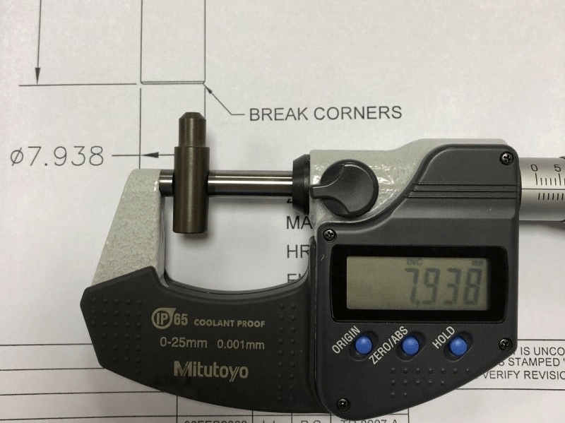
Four Rules for Using Tolerance Information Correctly
The Drawing Controls Acceptance
The approved 2D drawing defines individually toleranced dimensions, datum references, geometric controls, surface texture, threads and other acceptance requirements. A 3D model alone may not communicate these conditions. The CNC design for manufacturability guide provides additional guidance for connecting drawing decisions with machining access and functional risk.
General Tolerances Apply Only When Explicitly Invoked
A general-tolerance standard or title-block note applies only when it is stated on the drawing and accepted for the order. It must not override an individual dimension, a fit, a geometric control or another referenced specification.
Process Capability Is Feature-Specific
A supplier may hold a close tolerance on one bore without holding the same value across every dimension of a large part. Feature access, setup relationships, material movement and measurement strategy must be reviewed separately.
Measurement Method Must Match the Requirement
Instrument resolution alone does not prove measurement capability. Datum setup, temperature, calibration, fixturing, sampling and uncertainty all affect the inspection result.
ISO 2768 General Tolerances
ISO 2768 is applied to all drawing dimensions that do not carry an explicit tolerance callout. We use ISO 2768-m (Medium) as our default. Specify ISO 2768-f in the title block for finer general tolerance.
Part 1: Linear Dimensions (mm)
| Nominal Range | Fine (f) | Medium (m) ★ | Coarse (c) | Very Coarse (v) |
| 0.5–3mm | ±0.05 | ±0.10 | ±0.20 | — |
| 3–30mm | ±0.05 | ±0.20 | ±0.50 | ±1.0 |
| 30–120mm | ±0.10 | ±0.30 | ±0.80 | ±1.5 |
| 120–400mm | ±0.15 | ±0.50 | ±1.20 | ±2.5 |
| 400–1000mm | ±0.20 | ±0.80 | ±2.00 | ±4.0 |
| 1000–2000mm | ±0.30 | ±1.20 | ±3.00 | ±6.0 |
| 2000–4000mm | ±0.50 | ±2.00 | ±4.00 | ±8.0 |
★ ISO 2768-m is Samshion’s default for all CNC parts. State ISO 2768-f in your title block for finer general tolerance.
Part 1: Angular Dimensions
| Shorter Leg (mm) | Fine (f) | Medium (m) | Coarse (c) |
| Up to 10 | ±1° | ±1° | ±1°30′ |
| 10–50 | ±0°30′ | ±0°30′ | ±1° |
| 50–120 | ±0°20′ | ±0°20′ | ±0°30′ |
| 120–400 | ±0°10′ | ±0°10′ | ±0°20′ |
| Over 400 | ±0°5′ | ±0°5′ | ±0°10′ |
Part 2: Geometrical Tolerances (Form & Position)
| Feature Range | H | K | L |
| Up to 30 | 0.05 | 0.1 | 0.2 |
| 30–100 | 0.1 | 0.2 | 0.4 |
| 100–300 | 0.15 | 0.3 | 0.6 |
| 300–1000 | 0.2 | 0.4 | 0.8 |
| 1000–3000 | 0.25 | 0.5 | 1 |
GD&T — Geometric Dimensioning & Tolerancing
GD&T provides unambiguous definition of part geometry. We accept ASME Y14.5-2018 and ISO 1101 callouts. Our CMM verifies all geometric controls.
Form Controls
Flatness
CMM verified
Circularity
CMM verified
Cylindricity
CMM or roundness tester
Straightness
On shaft axis or surface line
Orientation Controls
Perpendicularity
CMM verified with datum
Angularity
CMM calculated
Parallelism
CMM or surface plate gauge
Circular Runout
Dial indicator on lathe / CMM
Location Controls
True Position
CMM with RFS or MMC
Concentricity
CMM median point verification
Symmetry
CMM median plane
Profile of Surface
CMM scanning probe
Common GD&T Callout Examples
Position of bolt hole pattern
Perpendicularity of a boss
Flatness of a sealing face
Runout on a turned shaft
Cylindricity of a bore
Profile of a curved surface
ISO Hole & Shaft Fits
ISO fits define the intended relationship between mating parts. The fit class controls whether parts rotate freely, locate precisely, or press together permanently.
| ISO Symbol | Fit Type | Condition | Typical Clearance/Interference | Torque to Assemble | Applications | Notes |
| H11/c11 | Loose Running | Large clearance | +60 to +240µm | Hand assembly | Non-precision pivots, agricultural, flexible shafts | Not for precision location |
| H9/d9 | Free Running | Significant clearance | +20 to +105µm | Hand assembly | Easily rotating shafts, lubricated bearings | Good for dirty or hot environments |
| H8/f7 | Close Running | Small clearance | +6 to +41µm | Hand assembly | Precision spindles, sliding fits | Needs good lubrication and alignment |
| H7/g6 | Sliding Fit | Minimal clearance | +2 to +29µm | Finger/hand | Precision location + free rotation | Bearings, pulleys, gears on shafts |
| H7/h6 | Easy Location | Zero to light clearance | 0 to +25µm | Hand | Standard precision shafts in housings | Most common bearing fit specification |
| H7/k6 | Transition | May be clear or light press | −10 to +18µm | Hand / light press | Precision location, repeatably removable | Gear hubs, locating pins |
| H7/n6 | Snug Fit | Light interference | −13 to +15µm | Light press | Parts located and occasionally removed | Bushings, disc hubs on shafts |
| H7/p6 | Push Fit | Light press | −21 to +6µm | Arbor press | Permanent location, light drives | Bushings pressed into housings |
| H7/s6 | Drive Fit | Medium press | −35 to −9µm | Hydraulic press | Coupling hubs, bearing inner race | Standard shrink-fit application |
| H7/u6 | Force Fit | Heavy press | −51 to −25µm | Heat shrink required | Permanent joints, safety-critical | Calculate interference stress carefully |
Surface Roughness Reference (Ra / N Grade)
Ra is the arithmetic mean deviation of the surface profile. Specifying Ra correctly saves money , don’t over-specify what your application doesn’t need.
| Ra (µm) | Ra (µin) | N Grade | How Achieved | Visual Description | Cost Factor | Typical Applications |
| 25 | 1000 | N12 | Rough milling / saw cut | Very rough — visible cut marks | 1× | Rough stock surfaces, non-functional |
| 12.5 | 500 | N10 | Rough milling | Coarse tool marks clearly visible | 1.2× | Non-mating rough machined surfaces |
| 6.3 | 250 | N9 | Standard milling | Tool marks visible on inspection | 1.4× | General machined non-contact surfaces |
| 3.2 | 125 | N8 | Standard CNC milling | Light marks, typical CNC output | 1.0× (baseline) | Default machined surface — most CNC parts |
| 1.6 | 63 | N7 | Fine milling / turning | Very smooth to touch | 1.3× | Sliding fits, non-sealing contact faces |
| 0.8 | 32 | N6 | Fine turning / reaming | Smooth, barely visible marks | 1.7× | Bearing fits, O-ring grooves, sliding seals |
| 0.4 | 16 | N5 | Grinding / fine turning | Near-mirror — reflects light | 2.5× | Precision bearing seats, hydraulic seal faces |
| 0.2 | 8 | N4 | Precision grinding | Mirror-like appearance | 4× | High-speed bearing seats, lapping joints |
| 0.1 | 4 | N3 | Lapping / honing | True mirror | 7× | Gauge surfaces, optical flats, precision hydraulics |
| 0.05 | 2 | N2 | Super-finish / lapping | Optical mirror quality | 15× | Metrology, optical mounts, CMM references |
Surface Roughness Design Rules
Only specify Ra where it matters
Leave unspecified surfaces at Ra 3.2µm (N8) default. Every Ra callout that requires additional operations adds cost and time.
Consider Ra vs. surface function
Sealing surfaces: Ra 0.4–0.8µm. Sliding fits: Ra 0.8–1.6µm. Static contacts: Ra 1.6–3.2µm. Rough machined non-contact: Ra 3.2–6.3µm.
Check finishing effect on Ra
Bead blasting raises Ra to 0.8–2.5µm. Anodizing adds minimal Ra change. Hard chrome brings Ra down. Electropolish reduces Ra by ~50%.
Achievable Tolerances by Manufacturing Process
The table below shows standard and precision tolerances achievable at Samshion. Tighter tolerances are possible in some cases , contact us to discuss.
| Process | Standard Tol. | Precision Tol. | Ultra-Precision | Surface Ra | Notes on Limitations |
| CNC Milling (3-axis) | ±0.05mm | ±0.02mm | ±0.01mm | 0.8–3.2µm | Tool deflection on thin walls / long reaches |
| 5-Axis CNC Milling | ±0.02mm | ±0.01mm | ±0.005mm | 0.4–1.6µm | Single setup eliminates datum error between ops |
| CNC Turning (diameter) | ±0.05mm | ±0.01mm | ±0.005mm | 0.4–1.6µm | Roundness / TIR to 0.003mm achievable |
| CNC Turning (length) | ±0.05mm | ±0.02mm | ±0.01mm | 0.8–1.6µm | Thermal growth affects long parts , inspect cooled |
| Cylindrical Grinding | ±0.01mm | ±0.005mm | ±0.002mm | 0.1–0.4µm | Best for shafts, bearing seats, gauge pins |
| Surface Grinding | ±0.01mm | ±0.005mm | ±0.003mm | 0.1–0.4µm | Excellent flatness (<2µm per 100mm) |
| Wire EDM | ±0.01mm | ±0.005mm | ±0.003mm | 0.4–1.6µm | Hard materials no problem; aspect ratio limits depth |
| Sink EDM | ±0.02mm | ±0.01mm | ±0.005mm | 0.2–3.2µm | Electrode wear must be compensated |
| Reaming | ±0.01mm | ±0.005mm | ±0.003mm | 0.4–0.8µm | Best for precision bore to H7 or tighter |
| Boring (single point) | ±0.01mm | ±0.005mm | ±0.003mm | 0.4–1.6µm | Large precision bores where reamer won’t reach |
| Sheet Metal Laser Cut | ±0.1mm | ±0.05mm | ±0.03mm | Per edge | Kerf width ~0.1–0.3mm depending on material+thickness |
| Sheet Metal Bending | ±0.5mm | ±0.2mm | ±0.1mm | N/A | Springback compensation applied; material variability |
| Injection Molding | ±0.2mm | ±0.1mm | ±0.05mm | Ra 0.05–1.6µm | Tooling quality and process stability critical |
| Die Casting | ±0.3mm | ±0.1mm | ±0.05mm (machined) | As-cast Ra 2–4µm | Secondary CNC for critical features |
| 3D Printing (SLA) | ±0.15mm | ±0.1mm | ±0.05mm | Ra 0.5–3µm | Layer orientation affects Z-axis accuracy |
| 3D Printing (SLS) | ±0.25mm | ±0.15mm | ±0.1mm | Ra 8–15µm | Functional accuracy; rough surface; post-processing |
| Metal Stamping | ±0.1mm | ±0.05mm | ±0.02mm | N/A | Precision stamping tooling and progressive dies |
Tolerances & Standards FAQ
Does SAMSHION apply one standard tolerance to every process?
No. Capability and acceptance depend on the process, feature, material, size, geometry, finishing and inspection method. The approved drawing and quotation define the project requirement.
When does ISO 2768 apply?
Only when the drawing explicitly invokes the applicable standard and class and that basis is accepted for the order. Individually toleranced dimensions and other referenced specifications take precedence.
Is a tighter tolerance always better?
No. A tighter requirement can increase setup, tooling, inspection, lead time and scrap risk. It should protect fit, sealing, motion, alignment or another verified function.
Why should I provide both a 3D model and a 2D drawing?
The model defines geometry. The drawing communicates tolerances, datums, fits, threads, surface texture, finish and inspection notes that may not exist in the model.
Can finishing change part dimensions?
Yes. Coatings, heat treatment, polishing, blasting and other operations may affect dimensions or measurement conditions. Critical post-finish requirements should be marked and reviewed before production.
How should I specify a critical fit?
State explicit limits or an accepted fit designation, identify the datum relationship and provide information about the mating component, coating and operating condition.
Can you provide inspection reports?
Project-specific reports may be available when requested and confirmed before production. The required characteristics, sampling and report format should be agreed during quotation. The quality assurance page describes the available control framework without implying that every document is included automatically.
What if my drawing contains conflicting requirements?
Production should pause for clarification. The model, dimensions, tolerances, notes and referenced standards must be aligned in an approved revision before manufacturing.