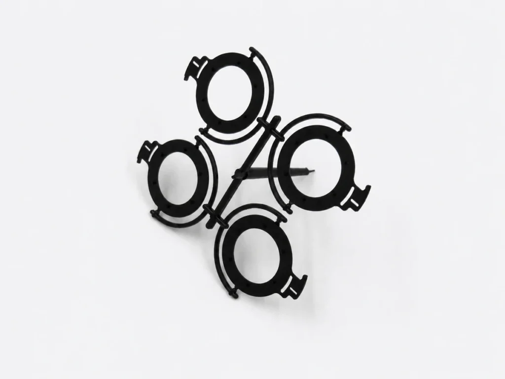
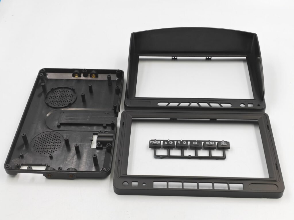
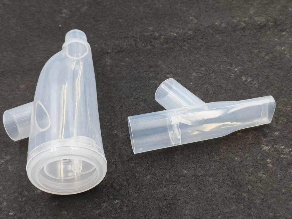
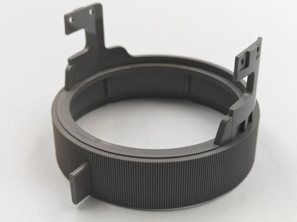
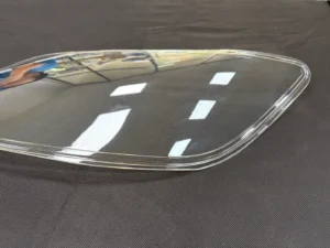
Injection Molding — From Prototype Tooling to Mass Production
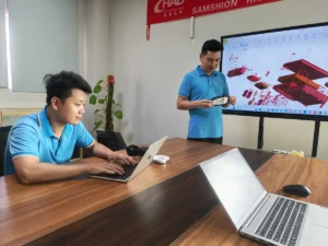
Whether you need 50 functional prototypes in 2 weeks, or 500,000 production parts per month, our team of 20+ mold engineers and quality specialists ensures every part meets your dimensional, cosmetic, and functional requirements.
ISO 9001:2015 Certified
Full quality documentation including FAI reports, PPAP, dimensional inspection reports, and material certifications provided with every order.
7-14 Days
Mold Fabrication Lead Time
50% Savings
vs. US/EU Tooling Cost
±0.05mm
Standard Part Tolerance
No MOQ
Order From 1 to 1M+ Parts
- Accepts STEP, IGES, SolidWorks, Parasolid, AutoCAD · Free DFM Analysis Included
| Process Specifications at a Glance | |
| Mold Steel | P20, H13, S136, NAK80 |
| Mold Hardness | 28–52 HRC (depending on grade) |
| Cavity Count | 1 to 32 cavities |
| Shot Weight | 1g – 5,000g per shot |
| Clamping Force | 80 – 1,600 tons |
| Max Mold Size | 1,500 × 1,200 × 800 mm |
| Part Tolerance | ±0.05mm (standard) / ±0.02mm (tight) |
| Surface Roughness | Ra 0.4 – 3.2 μm |
| Mold Life (steel) | 500,000 – 1,000,000+ shots |
| Mold Life (aluminum) | 5,000 – 20,000 shots |
What Is Plastic Injection Molding?
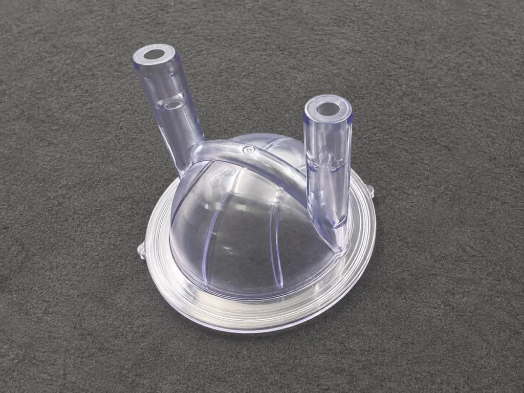
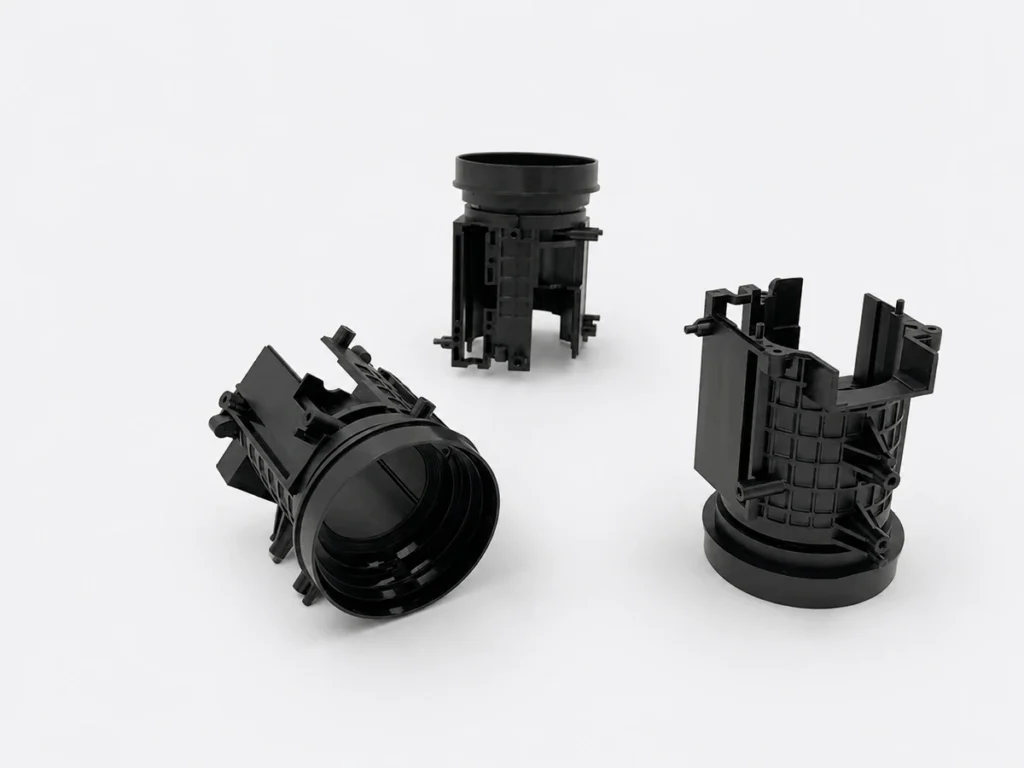
Injection molding is a molding method that uses pressure to fill in the mold with plastic liquid that is heated and melted, and then cools and solidifies inside the mold.The mold can be single cavity or multiple cavities with short cycle time.It can form the plastic products with complex shape and precise dimension.It has high production efficiency and is easy to achieve automatic operation.Injection molding is suitable for mass production and complex shape products and other molding processing fields.
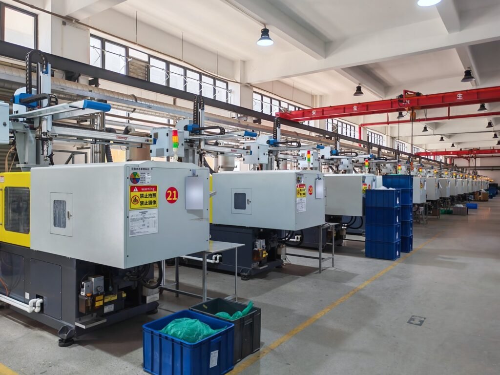
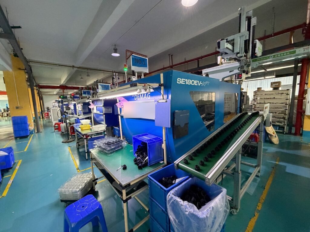
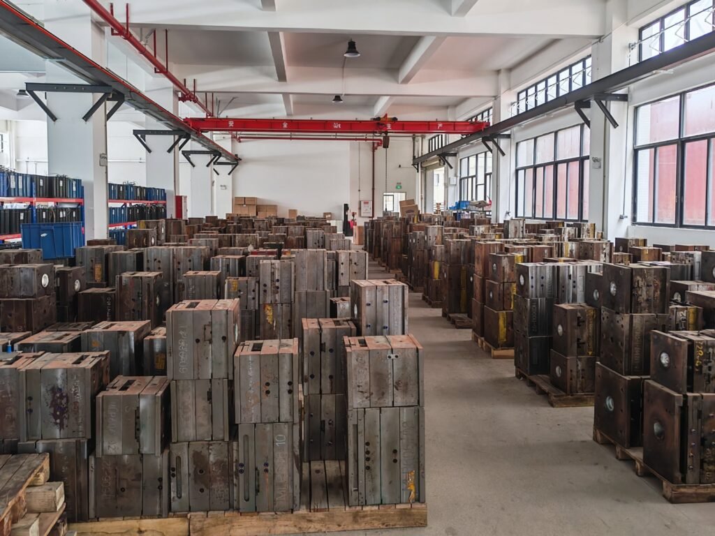
Samshion Rapid is a high quality rapid tooling and injection molding service supplier that can provide complete manufacturing solutions and no MOQ request.Our mold workshop and injection molding workshop are managed by experienced engineers.We can also provide you with a high level of professional technical support by our professional technical team so as to ensure that your parts are correctly completed at the first time.No matter for the sake of shortening the lauching time,saving the tooling cost,part price and extending the tooling life or for all these sakes,we can cooperate with you to meet your demands.Just upload your cad to get the quote and DFM freely.
What’s overmolding?
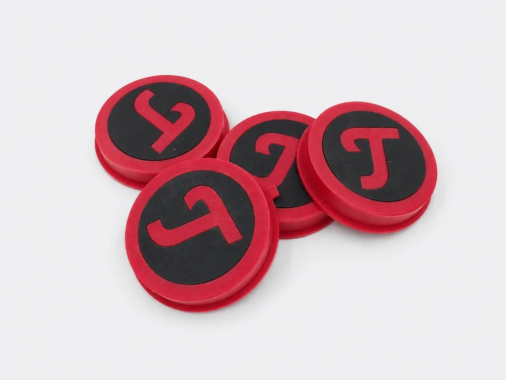
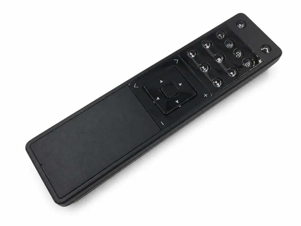
Overmolding is a kind of injection molding process, it is formed with a variety of materials stacked together to get a composite product.It is a composite part formed by placing a prefabricated part into another mold cavity for injection molding again, and stacking two kinds of materials together.
The advantages of overmolding is that it can achieve diversity of materials, diversity of colors and flexibility of design.It can also provide additional protection, appearance improvement or additional functions for the product.It is widely used in electronic products, tool handles and household goods and other fields, with good appearance and touch.
What’s insert overmolding?
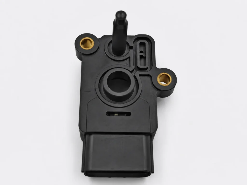
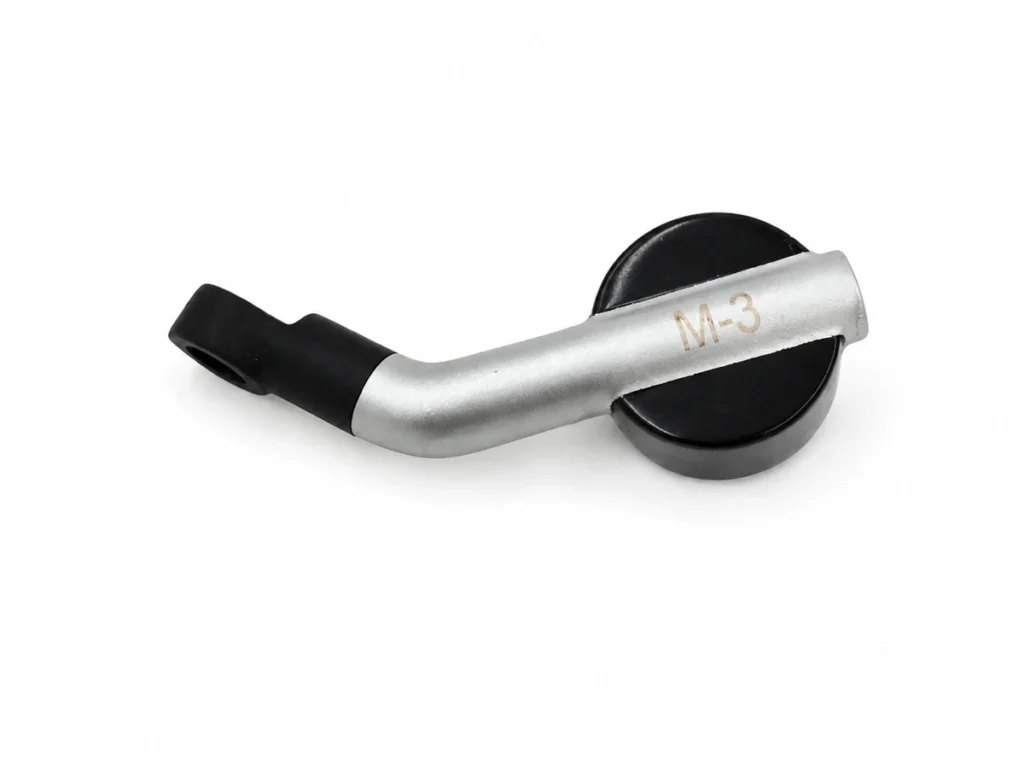
Insert overmolding is an injection molding process that metal inserts or other material parts are over molded into plastic products.It is molded by placing the metal insert into the mold cavity. This process is to inject the melted plastic into the mold cavity, so that the insert and the plastic are combined into a whole part.
The advantage of overmolding is that it can realize to get complex structural parts and functional parts with strong mechanical properties, functionality and good appearance.It is widely used in automotive, medical equipment, industrial machinery and electronic equipment and other fields.
Why Choose Injection Molding?
The most cost-effective manufacturing process for medium to high-volume plastic parts — delivering consistent quality at scale
Lowest Per-Part Cost at Volume
Once the mold is made, per-piece costs drop dramatically. For 10,000+ parts, injection molding delivers the lowest cost-per-part of any manufacturing method — often 70–90% cheaper than CNC machining at volume.
Best for: 500+ parts per run
Exceptional Repeatability
Every part is produced from the same steel mold cavity under controlled temperature and pressure. Dimensional variation between parts is typically less than ±0.05mm — critical for assemblies requiring tight fit.
Cp/Cpk process capability available
Wide Material & Color Flexibility
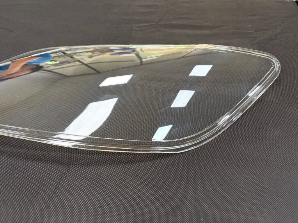
Choose from 100+ engineering-grade resins — rigid, flexible, transparent, flame-retardant, glass-filled, UV-stable, and more. Any Pantone or RAL color can be matched by our compounding team.
100+ resins · Any color · Overmolding
Superior Surface Finish
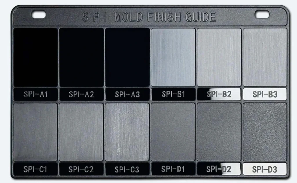
Mold cavities can be polished to optical clarity (SPI A1), textured with VDI or Mold-Tech patterns, or left with a standard machine finish. No post-processing needed for most cosmetic requirements.
SPI A1–D3 finishes available
Complex Geometry Support
Side actions, lifters, collapsible cores, and hot-runner systems allow you to mold complex undercuts and internal features that would require expensive multi-step machining operations.
Undercuts, threads, snap-fits
Sustainable & Efficient
Injection molding generates minimal material waste — up to 95% of sprues and runners can be re-ground and reused. Process optimization also reduces energy consumption versus alternative forming methods.
Low waste · Regrind-compatible
Which Mold Type Is Right for You?
We help you select the most cost-effective tooling path based on your volume, timeline, and budget
Prototype / Soft Tooling
Aluminum molds for fast, low-cost validation of part design, fit, and function before investing in steel tooling. Ideal for design iterations and pre-launch samples.
Mold Material
Aluminum (7075-T6)
Quantity
1-1,000 pcs
Mold Life
5,000 – 20,000 shots
Lead Time
7 – 10 days
Advantages
- Fastest mold delivery: 7–10 days
- Lowest upfront tooling investment
- Easy cavity modifications if design changes
- Real injection-molded material (not 3D printed)
- Perfect for investor demos and market testing
Limitations
- Limited mold life (up to 20K shots)
- Not suitable for abrasive glass-filled materials
Best for: Startups, design validation, pre-launch samples
Bridge / Pilot Tooling
Semi-hardened steel molds for production-quality parts while your production tooling is being built, or for products with uncertain long-term volumes.
Mold Material
P20 Steel (pre-hardened)
Quantity
1,000 – 50,000 pcs
Mold Life
100,000 – 500,000 shots
Lead Time
10 – 18 days
Advantages
- Production-quality surface finish
- Handles most engineering resins
- Good for market launch with real demand data
- Can be upgraded to full production spec
- Suitable for low to mid-volume production
Limitations
- Higher upfront cost than aluminum
- Not optimal for very high volumes
Best for: Market launch, bridge production, mid-volume
Production / Hard Tooling
Fully hardened, precision-machined steel molds built for millions of cycles with hot-runner systems, automated ejection, and full surface treatment.
Mold Material
H13 / S136 Hardened Steel
Quantity
50,000 – 10M+ pcs
Mold Life
500,000 – 2,000,000+ shots
Lead Time
18 – 35 days
Advantages
- Lowest per-part cost at high volumes
- Multi-cavity (4, 8, 16, 32 cavity options)
- Hot-runner systems eliminate sprue waste
- Automated ejection for lights-out production
- Compatible with all engineering resins incl. glass-filled
Limitations
- Higher upfront investment
- Longer lead time for mold build
Best for: Mass production, consumer goods, automotive
| Comparison Factor | Prototype Tooling | Bridge Tooling | Production Tooling |
| Upfront Tooling Cost | Low | Medium | High |
| Per-Part Cost (10K+) | Highest | Medium | Lowest |
| Mold Lead Time | 7–10 days | 10–18 days | 18–35 days |
| Part Quality | Good | Production Grade | Production Grade |
| Design Change Ease | Easy | Moderate | Difficult / Costly |
| Max Part Volume | ~20K pcs | ~500K pcs | Unlimited |
| Glass-Filled Resins | Limited | Yes | Yes |
| Multi-Cavity Support | No | 1–2 cavities | Up to 32 cavities |
Material of plastic injection molding
Injection molding is the most common method of producing plastic parts, and there are many kinds of plastic materials used for injection molding.When selecting injection molding materials, it is necessary to consider the physical properties, chemical properties, environmental protection and production costs and other factors.Different materials have different properties and need to be selected according to actual needs.
| Material | Density | Heat Resistance | Shrinkage Rate | Typical Applications |
|---|---|---|---|---|
| ABS | 1.05 g/cm³ | 80–100°C | 0.4–0.7% | Consumer electronics housings, automotive interior, appliances |
| PP (Polypropylene) | 0.90–0.91 g/cm³ | 100–120°C | 1.0–2.5% | Packaging, automotive, living hinges, medical containers |
| PE (Polyethylene) | 0.94–0.96 g/cm³ | 80–90°C | 1.5–3.0% | Bottles, containers, pipes, consumer goods |
| PS (Polystyrene) | 1.05 g/cm³ | 60–80°C | 0.3–0.6% | Disposable packaging, toys, CD cases, medical disposables |
| Material | Density | Heat Resistance | Shrinkage Rate | Typical Applications |
|---|---|---|---|---|
| PC (Polycarbonate) | 1.20 g/cm³ | 120–130°C | 0.5–0.7% | Optical lenses, safety equipment, electronics, lighting |
| Nylon 6 / PA6 | 1.14 g/cm³ | 80–120°C | 0.6–1.4% | Gears, bearings, structural components, cable ties |
| Nylon 66 / PA66 | 1.14 g/cm³ | 90–120°C | 0.8–1.5% | Automotive under-hood, high-load mechanical parts |
| POM / Delrin | 1.41 g/cm³ | 90–100°C | 1.8–2.0% | Precision gears, pump parts, bearings, valve bodies |
| PC/ABS Blend | 1.14 g/cm³ | 90–110°C | 0.4–0.6% | Automotive dashboards, laptop shells, power tools |
| PBT | 1.30 g/cm³ | 120–150°C | 1.5–2.2% | Electrical connectors, automotive sensors, switches |
| Material | Density | Heat Resistance | Shrinkage Rate | Typical Applications |
|---|---|---|---|---|
| PEEK | 1.32 g/cm³ | 250°C continuous | 1.0–1.3% | Medical implants, aerospace brackets, semiconductor parts |
| PPS | 1.35 g/cm³ | 200–220°C | 0.6–1.4% | Chemical pumps, automotive fuel systems, electrical parts |
| LCP | 1.40 g/cm³ | 240–280°C | 0.1–0.3% | Ultra-thin connectors, 5G antenna parts, micro-components |
| PSU / PPSU | 1.24 g/cm³ | 150–190°C | 0.6–0.8% | Medical sterilizable parts, plumbing, aerospace |
| Material | Density | Heat Resistance | Shrinkage Rate | Typical Applications |
|---|---|---|---|---|
| TPU (Thermoplastic PU) | 1.12 g/cm³ | -40 to 80°C | 1.0–2.0% | Phone cases, footwear, cables, seals, medical tubing |
| TPE / SEBS | 0.90 g/cm³ | -50 to 120°C | 1.5–2.5% | Soft-touch grips, overmolding, baby products |
| Silicone (LSR) | 1.12 g/cm³ | -60 to 200°C | 2.5–3.5% | Medical seals, baby nipples, keypads, wearable gaskets |
Don’t see your material? Contact our material engineers → We source specialty resins on request.
Mold Surface Finish Standards
Choose the right finish for your application — from optical-grade polish to industrial texture
SPI Finish Standards
Society of the Plastics Industry standards for mold cavity finish
| SPI Grade | Method | Surface Roughness | Typical Application |
| SPI A-1 | Grade #3, 6000 Grit Diamond | Ra ≤0.025 μm | Optical lenses, mirrors, clear parts requiring maximum clarity |
| SPI A-2 | Grade #6, 3000 Grit Diamond | Ra ≤0.05 μm | High-gloss cosmetic parts, premium consumer products |
| SPI A-3 | Grade #15, 1200 Grit Diamond | Ra ≤0.1 μm | Semi-gloss, most cosmetic-grade consumer plastic parts |
| SPI B-1 | 600 Grit Paper | Ra 0.05–0.10 μm | General cosmetic surfaces, automotive interior trim |
| SPI B-2 | 400 Grit Paper | Ra 0.10–0.15 μm | Low-sheen surfaces, non-critical cosmetic parts |
| SPI B-3 | 320 Grit Paper | Ra 0.20–0.30 μm | Medium smooth finishes |
| SPI C-1 | 600 Stone | Ra 0.30–0.35 μm | Functional non-cosmetic parts, industrial components |
| SPI C-2 | 400 Stone | Ra 0.35–0.40 μm | Utility parts |
| SPI D-1 | Dry Blast Glass Bead | Ra 0.8–1.0 μm | Matte/textured appearance, hides surface defects |
| SPI D-3 | Dry Blast #24 Oxide | Ra 3.2 μm | Heavy matte, anti-glare, industrial use |
Mold Texture Options
EDM and chemical texturing for branded surface appearances
VDI 3400 Texture
EDM spark erosion texture scale 0–45
Mold-Tech Texture
Industry-standard leather & fine grain patterns
Custom Logo / Text
Molded-in branding on A-surface
Lifter Line Minimization
Precision alignment to hide parting lines
Post-Processing Options
- Painting & Coating
- Insert Threading (heat-set)
- Pad Printing
- Chrome / Metallic Plating
- Hot Stamping / Foiling
- Ultrasonic Welding
- Assembly & Packaging
- Full Dimensional Inspection
From CAD File to Production Parts
A proven, transparent process with clear milestones at every stage
Submit CAD Files & Requirements
Upload your 3D CAD files (STEP, IGES, Parasolid, SolidWorks, or AutoCAD format) along with your material preference, quantity, tolerance requirements, and surface finish specification. Our engineers begin review immediately upon receipt.
DFM Analysis & Quotation
Our mold engineers perform a full Design for Manufacturability (DFM) review — checking for moldability issues including draft angles, wall thickness, undercuts, and gate locations. You receive a detailed DFM report highlighting any concerns and recommended design changes, plus a complete quote covering tooling cost and per-part pricing.
Design Approval & PO Confirmation
Review the DFM report and quotation. Our engineers are available to discuss any design modifications that could improve quality or reduce cost. Once you approve the DFM and confirm the purchase order, mold fabrication begins immediately.
Mold Design & Engineering
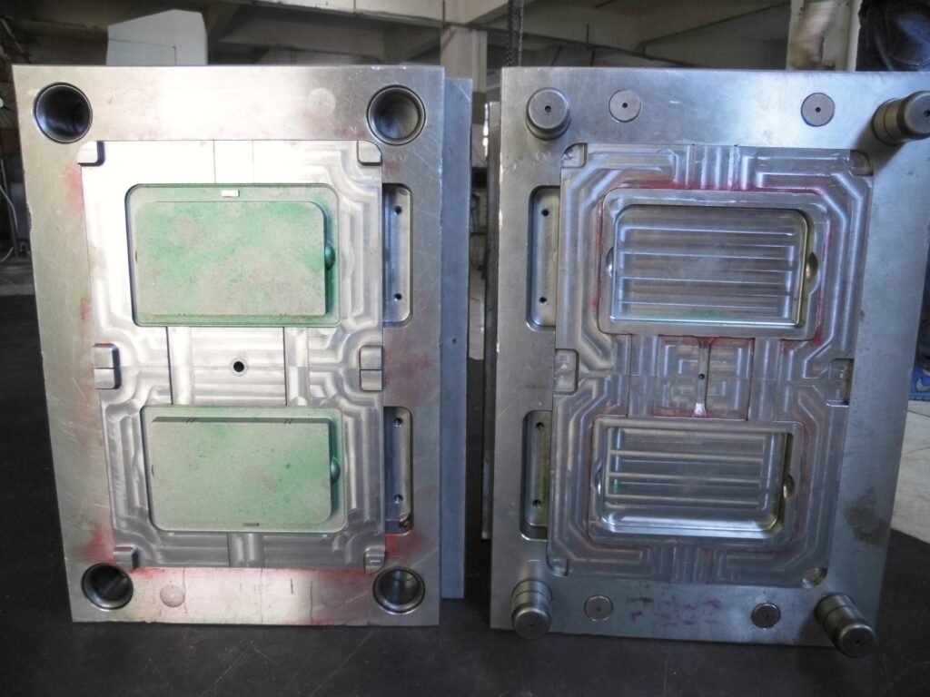
Our mold design team creates detailed 3D mold designs including cavity & core layout, parting line definition, runner system, gate design, cooling channel layout, ejection system, and side action design. All designs undergo internal review before machining begins.
Mold Fabrication
CNC machining, EDM (sinker and wire), high-speed milling, and grinding operations produce the mold components. Critical dimensions are verified with CMM inspection at each manufacturing stage. Surface finish operations (polishing, texturing, coating) are completed to specification.
T1 Trial Shot & Inspection
First article trial shots (T1) are produced and subjected to a comprehensive dimensional inspection. A full First Article Inspection (FAI) report is generated documenting all critical dimensions against the nominal drawing. Any required adjustments are made to the mold before production approval.
Production & Quality Control
Approved production runs proceed with in-process SPC monitoring for critical dimensions. Finished parts receive visual inspection, dimensional sampling, and function testing as specified. All parts are cleaned, packaged, and labeled per your requirements before shipment.
Plastic Injection Molding Process
Preparation before injection molding
- Raw material preparation: including plastic particle , plastic drying, pigment mixing.
- Tooling preparation: set up the tooling on the machine and do the inspection and maintainence to ensure the tooling quality and performance so as to meet the production requirements.
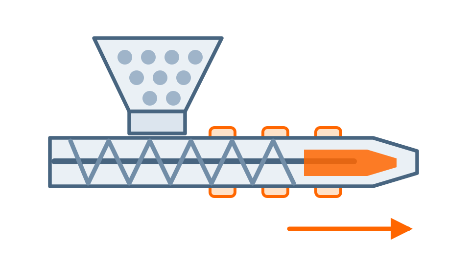
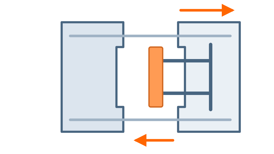
- The dry particles are poured into the hopper of the injection molding machine,when the particles are fed into the barrel,they are heated and melted at the same time.
The injection molding process is divided into six cycle steps
mold closing, injection, pressure holding, cooling, mold opening and ejection. These six stages directly determine the molding quality of the product, and these six stages are a complete continuous process.
Step 1 - Mold closing
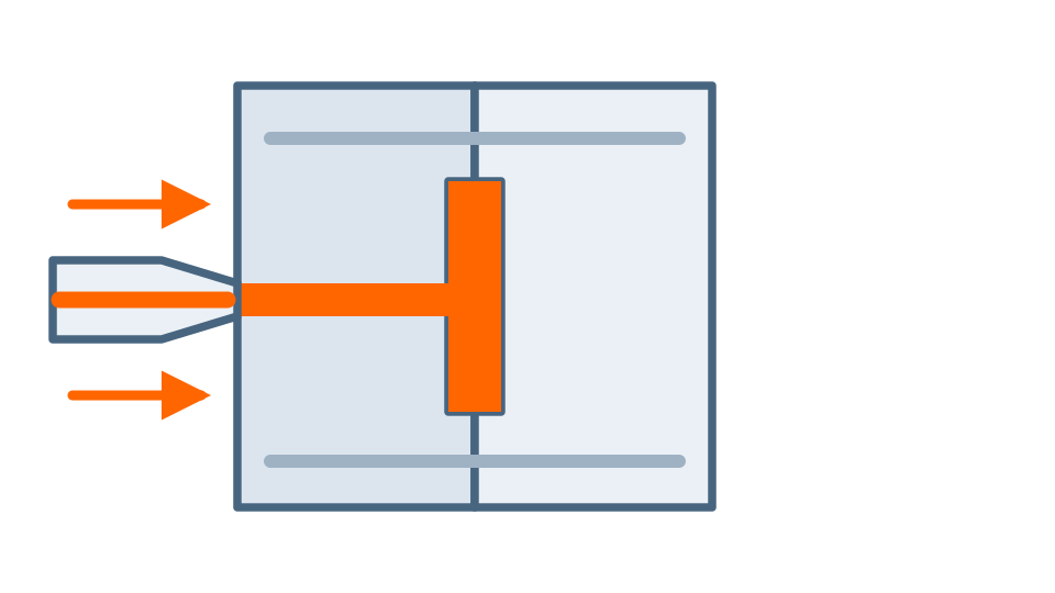
Supply the mold with enough clamping force to resist the cavity pressure caused by melting plastic entering the cavity.It can prevent the mold from opening, resulting in bad products.
Step 2 - Injection
The melted plastic is injected into the cavity . The injection molding machine controls the plastic flow speed and pressure in the injection process by controlling the screw rod speed and the injection pressure.
Step 3 - Holding Pressure
The function of the pressure holding stage is to continuously apply pressure to the mold cavity, compacts the melted plastic and increases the plastic density to compensate for the plastic’s shrinkage, so as to ensure the part’s dimensional accuracy and consistency.
Step 4 - Cooling
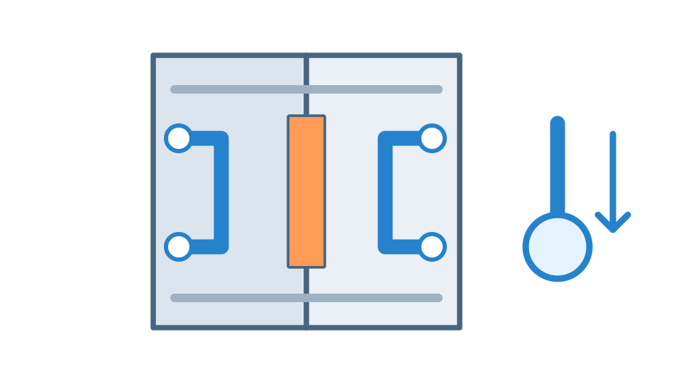
After the plastic is injected into the cavity,the cooling system in the mold reduces the mold temperature by cooling water or cooling oil, which helps the plastic solidify quickly.
Step 5 - Mold opening
After the plastic is solidified,the injection molding machine will open the mold by hydraulic or mechanical system.
Step 6 - Ejection
After the mold is opened, the ejector system is activated and the parts are ejected.
Quality Assurance
Our quality management system covers incoming material, in-process monitoring, and final inspection — with full documentation for every order
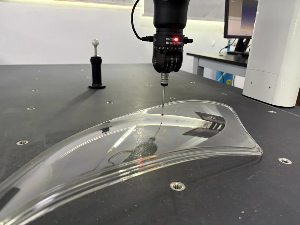
CMM Inspection
Renishaw coordinate measuring machines for 100% first-article dimensional verification
XRF Analysis
Fluorescence spectroscopy verifies resin composition and ensures RoHS/REACH compliance
SPC Monitoring
Statistical Process Control tracks key dimensions in real-time across production runs
Full Documentation
FAI reports, material certs, PPAP packages, inspection reports — all digitally archived
Documents We Provide
- First Article Inspection (FAI) Report
- Production Part Approval (PPAP)
- Material Certificates / Mill Certs
- Dimensional Inspection Report
- Process Capability Study (Cp/Cpk)
- RoHS / REACH Compliance
- Packing List & COC
- MSDS / SDS Sheets
Quality Certifications
ISO 9001:2015
Quality Management System — full facility and all processes
RoHS 3 Compliant
Verified via XRF spectroscopy for all plastics and metal inserts
REACH Compliant
SVHCs screened in all materials per EU regulation
PPAP Capable
Level 1–3 PPAP packages available for automotive customers
Injection Molding Design Guidelines
Following these guidelines reduces tooling cost, improves part quality, and avoids the most common DFM issues we see in submitted designs
Wall Thickness
Recommended: 1.5 – 4.0mm (uniform throughout part)
- Uniform walls reduce warpage, sink marks, and cycle time. Design ribs to 50–60% of wall thickness.
- Thick sections cause sink marks, warpage, and extended cycle time. Thin sections cause incomplete fill and surface defects.
If you need structural rigidity, use ribs instead of thicker walls. Ribs should be 50–60% of nominal wall thickness.
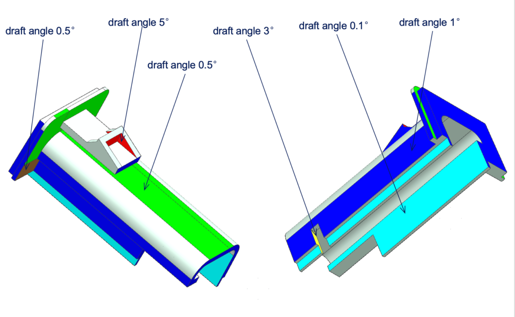
Draft Angles
Minimum: 0.5° · Recommended: 1–3° per side
- Adequate draft allows clean ejection, preserves surface finish, and extends mold life significantly.
- Zero-draft walls cause drag marks, galling, and part sticking — leading to ejection damage and shortened tool life.
Textured surfaces require additional draft — typically 1° per 0.025mm (0.001″) of texture depth.
Undercuts & Side Actions
Design undercuts only where functionally necessary
- External undercuts can often be handled with side actions. Internal undercuts may require lifters or collapsible cores.
- Excessive or deep undercuts increase mold complexity, cost, and cycle time significantly.
Share your design intent early — our DFM team can often redesign features to eliminate costly side actions.
Gate Location
Gates should be placed at thickest section of part
- Proper gate placement ensures complete fill, minimizes weld lines, and puts gate witness marks in non-cosmetic areas.
- Poor gate location causes short shots, weld lines in visible areas, and jetting defects on cosmetic surfaces.
For transparent parts, gate location is critical to avoid visible flow marks. Our engineers will advise during DFM review.
Radii & Sharp Corners
Minimum inside radius: 50% of wall thickness
- Generous radii distribute stress, improve material flow, and reduce stress concentration in finished parts.
- Sharp internal corners create stress risers, poor flow, and mold wear — leading to cracks in service.
Standard recommendation: R = 0.5T for inside radii and R = 1.5T for outside radii (T = wall thickness).
Sink Marks & Ribs
Rib thickness: 50–60% of nominal wall · Rib height: max 3x wall thickness
- Correctly proportioned ribs add rigidity without causing sink marks on the opposite surface.
- Ribs that are too thick create visible sink marks on the A-surface (cosmetic side) of parts.
For high-gloss cosmetic surfaces, reduce rib thickness to 40% of wall and polish the A-side cavity to SPI A2.
Why choose us?
Injection molding is usually suitable for small batch or high volume production with more materials choices and color flexibility.Injection molding has a wide range of applications and is suitable for various shapes and sizes which can produce a variety of plastic products.
All-round services
We not only provide you the rapid tooling service,but also provide prototyping,CNC and traditional mold manufacturing and injection molding as well as the complete product manufacturing solutions
Competitive price
We are the source factory, every manufacturing process is completed in our own factory, both manufacturing costs and production time are within our control.
DFM feedback
Upload your 3D CAD data for a quote, do a full Design for Manufacturing (DFM) analysis for free, and you'll get better feedback while saving more money and time.
Strict quality control
Certified to ISO 9001:2015, our laboratory has deployed powerful measuring instruments and an excellent team of quality engineers, combined with a strict quality control process to ensure that every piece is of high quality before it can be shipped.
No MOQ
You can order according to your inventory, no minimum order requirement.
Rapid quotation
A rapid and accurate and transparent quote can be achieved within 24 hours.
Injection Molding Applications by Industry
Plastic injection molding is a common processing method and widely used in various fields. injection molding technology provide important support for product manufacturing in different fields with the advantages of its molding speed, high production efficiency, high product precision.
Automotive
- Dashboard panels & trim
- Door handle mechanisms
- HVAC duct components
- Sensor housings & brackets
- Fluid reservoir caps
Common Materials: ABS, PP, PA66, POM, PC/ABS
Medical & Healthcare
- Syringe bodies & plungers
- Diagnostic device housings
- Surgical instrument handles
- Drug delivery device components
- Laboratory consumables
Common Materials: PP, PC, ABS, Ultem, PEEK, LSR
Consumer Electronics
- Phone cases & bezels
- Laptop keyboard frames
- Remote control housings
- USB/charging port covers
- Wearable device enclosures
Common Materials: ABS, PC/ABS, PP, TPU
Industrial Equipment
- Valve bodies & actuators
- Pump housings
- Cable management components
- Safety guard panels
- Machine operator interfaces
Common Materials: POM, PA, PBT, GF-PA, PPS
Aerospace & Defense
- Interior cabin components
- Connector housings
- Environmental seals
- Structural brackets (non-load bearing)
- Ground support equipment
Common Materials: PEEK, PSU, PPSU, Ultem, LCP
Consumer Goods
- Appliance housings & knobs
- Toy components & assemblies
- Sports equipment parts
- Personal care device bodies
- Storage & organization products
Common Materials: PP, ABS, PE, TPE, Nylon
Frequently Asked Questions
What is the minimum order quantity (MOQ) for injection molding?
There is no minimum order quantity. We can produce as few as 1 part from a prototype mold. However, injection molding becomes most cost-competitive at volumes of 500+ parts, where the tooling cost is amortized across enough parts. For very small quantities (1–50 pcs), we often recommend vacuum casting or CNC machining instead — our engineers will advise you on the most cost-effective process for your volume.
How much does injection mold tooling cost?
Tooling cost depends on part size, complexity, and mold type. As a rough guide: simple prototype aluminum molds start around $300–$1,500; bridge steel molds range from $2,000–$15,000; production hardened steel molds typically run $8,000–$80,000+. All quotes include a detailed DFM analysis at no charge. We’re typically 40–60% less expensive than US/EU mold shops for equivalent quality.
How long does it take from CAD file to first parts?
For prototype/aluminum tooling: 7–10 days from PO to T1 samples. For bridge steel tooling: 10–18 days. For production hardened steel tooling: 18–35 days. After T1 approval, production runs can begin within 1–3 business days. Expedited tooling is available on request — contact us to discuss your deadline.
Can you match a specific color (Pantone or RAL)?
Yes. We can color-match to any Pantone, RAL, or customer-supplied color chip. Colors are achieved through master-batch color concentrate blending. For critical color matches, we produce color-match trial shots and send samples for approval before full production begins. Note that some resins have limited color options (e.g., natural-colored PEEK and PPS).
Do you offer overmolding and insert molding?
Yes, both processes are available. Overmolding allows us to mold a second material (often TPE/TPU) over a rigid substrate — commonly used for soft-grip handles, waterproof seals, and aesthetic accents. Insert molding involves placing metal inserts (threaded brass, stainless, or aluminum) into the mold before injection, producing parts with permanently integrated fasteners. Please mention overmolding or insert molding requirements in your initial inquiry.
What CAD file formats do you accept?
We accept STEP (.stp, .step), IGES (.igs, .iges), Parasolid (.x_t, .x_b), SolidWorks (.sldprt, .sldasm), AutoCAD (.dwg, .dxf), Catia V5 (.CATPart), and STL (.stl). STEP format is recommended for best geometric accuracy. We can also work from 2D engineering drawings (PDF or DWG) if you don’t have 3D CAD files available.
Do you provide design assistance if my part has DFM issues?
Absolutely. Our DFM review is not just a pass/fail check — we provide specific recommendations to improve moldability, reduce tooling cost, and enhance part quality. For complex projects, we offer Engineering Change Order (ECO) support to revise your design before tooling commences. This service is included free of charge with every project.