
Customized CNC Bending Service
Speed up your development cycle with our on-demand metal bending services. Simply upload your 3D models to get started. Our engineering team will quickly analyze your geometric shape, offer free DFM audits along with competitive pricing, and efficiently provide services. From individual prototypes to large-scale OEM production, we can provide precise solutions according to your schedule.
- From Rapid Prototype to Mass Production
- High Precision with Intelligent Angle Compensation
- Accelerated Lead Times via Digitized Manufacturing Workflows
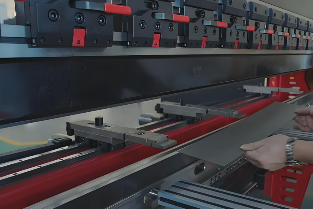
What is CNC Bending?
CNC (Computer Numerical Control) bending is the core process of modern precision sheet metal processing. Through high-precision CNC bending machines, we convert digital drawings into precise geometric shapes. Unlike traditional manual or semi-automatic bending, CNC systems can accurately control pressure, speed, and rear material displacement, ensuring that even the most complex parts can maintain amazing consistency and strict tolerance standards in multiple processes.
At Samshion, it is not only a manifestation of power, but also the art of algorithms. We adopt a multi axis linkage CNC system, combined with real-time angle detection and rebound compensation technology for sheet metal, to automatically correct physical differences between different materials. This means that from the first prototype to mass production on a scale of 10000 pieces, every corner is precise and error free. For high demand industrial applications, this represents lower scrap rates, more perfect assembly coordination, and shorter delivery cycles.
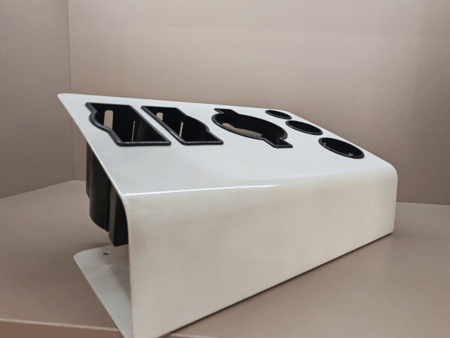
Precision
CNC back-gauge positioning ±0.1mm. Laser angle sensor verifies every bend in real-time, compensating for springback automatically.
Repeatability
Once programmed, every part in a batch is identical. No operator-to-operator variation. Critical for assemblies requiring consistent fit.
Speed
A simple 4-bend bracket takes under 2 minutes from flat blank to finished part. Complex enclosures with 12+ bends in under 8 minutes.
Versatility
7 bending methods available — air bending, coining, U-channel, roll, step, rotary, and bottom bending — covering any geometry.
Why Choose Samshion for Metal Bending?
All bending in-house, same-day quoting, free DFM review — and 30–40% cheaper than US or European suppliers.
Cost-Effective with No Tooling Investment
Eliminate expensive mold costs and long lead times with our universal CNC setups. Our agile tooling system adapts instantly to your specific geometry, enabling custom components with zero upfront investment—optimizing your budget from initial concept to final market delivery.
Flexible Customization & Complex Geometries
Handle intricate designs, multiple bends, various materials (aluminum, stainless, steel, copper), and thicknesses – from single prototypes to large-scale OEM production without redesigns.
Free Expert Support & Instant Feedback
Accelerate your development cycle with our dedicated engineering team and automated DFM analysis. We will offer feedback on every file to optimize bend sequences, reduce material waste, and ensure structural integrity—giving you the confidence to move from digital design to physical part within one day.
CNC Sheet Metal Bending Methodologies
This technology represents the core technology used to transform flat metals into complex 3D structures. The following is a professional overview of the main technologies used in our company’s high-precision CNC equipment. Detailed disassembly of each process of CNC bending.
CNC Air Bending
Most common method. The punch drives the sheet partially into the die, leaving a controlled gap. Bend angle is determined by punch travel depth, not die geometry.
- Any angle from a single die set
- Fast tooling changeover
- Works for most sheet metals
Slight springback — compensated automatically by CNC sensor.
CNC Bottoming
The sheet is pressed fully onto the bottom of the die, producing a sharp, well-defined bend angle. Less springback than air bending, more forgiving than coining.
- Reduced springback vs. air bending
- Good angle consistency
- Lower force than coining
Die angle must match desired bend angle. Less flexible than air bending.
CNC Coining
Extreme pressure forces the metal to fully conform to the punch and die profile. No springback because the material is plastically deformed through its full thickness.
- Highest angle accuracy ±0.25°
- No springback — no compensation needed
- Excellent for small intricate parts
Requires 5–8× more tonnage than air bending. Best for small flanges.
CNC U-Channel Bending
Parallel punches form both flanges simultaneously, creating a U-shaped channel or box profile in a single stroke. Maintains consistent channel width throughout the part length.
- Single-stroke channel forming
- Consistent width along full length
- Ideal for rack profiles and enclosures
Channel width is fixed by the tooling — requires custom tooling for non-standard widths.
Roll Bending
Three powered rollers gradually curve a flat sheet into a cylindrical or conical form. The radius is adjusted by repositioning the rollers — no fixed tooling required.
- Any radius from tight coil to gentle curve
- No tooling cost — rollers adjust continuously
- Tubes, cones, and curved panels
Not suitable for sharp corners or angular bends.
Step Bending
A series of closely spaced small-angle bends create an approximation of a large-radius curve. Effective where roll bending would require extremely wide rollers.
- Achieves large radii using standard V-dies
- No special tooling needed
- Good for panels and long parts
Step marks visible on part surface — may require finishing if cosmetic.
Rotary Bending
A rotating die head grips and bends the sheet around a mandrel in a continuous rotating motion. Produces smooth compound curves and avoids marring polished surfaces.
- No surface marking — ideal for polished SS
- Compound curve capability
- Good for large-radius architectural parts
Slower cycle time than press brake. Best for specialty cosmetic parts.
Materials We Bend
Material selection affects bend radius, minimum flange height, and springback. Our engineers select the optimal V-die opening and punch radius for each material and thickness combination.
| Material | Grades | Thickness Range | Min Bend Radius | Springback | Bending Notes |
| Carbon / Mild Steel | Q235B, SPCC, DC01 | 0.5–12mm | 1.0×T | Low | Easiest to bend — ideal starting material. Consistent springback, air bending works well. |
| Stainless Steel 304 | 304, 304L | 0.5–10mm | 1.5×T | Medium | Higher springback than carbon steel. CNC sensor compensation essential for angular accuracy. |
| Stainless Steel 316L | 316, 316L | 0.5–8mm | 1.5×T | Medium | Similar to 304 but slightly more ductile. Preferred for medical and marine applications. |
| Aluminum 5052 | 5052-H32 | 0.5–10mm | 1.0×T | Low | Most bendable aluminum alloy — excellent for enclosures, panels, and general sheet work. |
| Aluminum 6061 | 6061-T6 | 0.5–6mm | 2.0×T | Medium | Harder than 5052 — requires larger bend radius to avoid cracking. Anneal if <1.5mm radius needed. |
| Galvanized Steel | DX51D, SGCC | 0.5–4mm | 1.0×T | Low | Zinc coating can crack on tight bends — keep radius ≥1.5×T for cosmetic zinc integrity. |
| Copper | C11000, C10100 | 0.3–6mm | 0.5×T | Very low | Highly ductile — very easy to bend. Work-hardens after repeated bends; anneal if needed. |
| Brass | C26000, C36000 | 0.3–4mm | 1.0×T | Low | Brittle at low temper — use half-hard or annealed brass for tight bends. Cosmetically excellent. |
| Titanium Gr2 | Grade 2 | 0.5–3mm | 2.5×T | High | High springback — requires significant overbend and laser correction. Specialist fixture recommended. |
T = Material Thickness. Min bend radius = inside bend radius at the punch tip.
Our bending Technical Capabilities & Specifications
Specification | Capability |
Bending Method | High-Precision Multi-Axis CNC Press Braking |
Standard Tolerances | ±0.1mm (Linear) / ±0.5° (Angular) |
Max Press Force | 50 Tons – 800 Tons |
Max Bending Length | Up to 6,000 mm (236″) |
Thickness Range | 0.5 mm – 20 mm (Material dependent) |
Materials Supported | Aluminum, Stainless Steel, Carbon Steel, Copper, Brass,acrylic |
Backgauge System | 6-Axis High-Speed CNC Synchronization |
Surface Finishes | No-Mar Bending, Brushed, Mirror-Finish Protection and so on |
Production Volume | Rapid Prototyping to High-Volume OEM Runs |
Metal Bending Design Guidelines
Follow these rules to get dimensionally accurate bent parts and avoid re-work. Our DFM review checks all of these before production starts.
Bend Radius Rules
Min inside radius ≥ 1× material thickness
Bending tighter than 1×T cracks the outer fiber of the sheet. For stainless steel, use 1.5×T minimum. For 6061-T6 aluminum, use 2×T. Always specify inside radius on your drawing — not outside radius.
Larger radius = easier bending = less cracking risk
When tolerance allows, specify the largest acceptable inside radius. This reduces bending force, die wear, and the risk of outer-fiber cracking — especially on work-hardened or heat-treated materials.
Specify grain direction on aluminum
Aluminum bends more easily perpendicular to the rolling direction. Bending parallel to the grain (same direction as rolling marks) on 5052 or 6061 increases crack risk on the outer surface.
Flange Height Rules
Min flange height = 3× material thickness + inside radius
Flanges shorter than this cannot be positioned against the back-gauge repeatably. The back-gauge finger cannot register the sheet edge accurately on very short flanges, causing angle error.
Standard minimum flange: 6mm or 3×T, whichever is larger
For 2mm steel, the minimum is 6mm. For 4mm steel, the minimum is 12mm. If your design requires a shorter flange, please consult our engineers — in some cases a relief cut allows shorter forming.
Equal flanges simplify fixturing and reduce error
Where possible, design bent parts with equal or near-equal flange lengths on both sides of a bend. Asymmetric parts with very short flanges on one side are harder to hold and more prone to angular deviation.
Feature-to-Bend Clearances
Keep holes ≥ (2×T + inside radius) from bend lines
Holes or slots within the bend zone distort into ovals during forming. The minimum safe distance from hole edge to bend line is twice the material thickness plus the inside bend radius.
Keep slots and cutouts clear of bend zone
Slots that run across or near a bend line act as stress risers. Material tears at the slot end during bending. Extend the slot end at least 3×T beyond the bend line, or add a relief hole at the slot terminus.
Add bend relief notches at intersecting bends
Where two bends meet at a corner (e.g. a box corner), add a small relief notch or hole at the intersection point. Without it, material stacks up at the corner during bending and causes dimensional distortion.
Bend Sequence & Tolerancing
Think in bend sequences — inner bends first
On multi-bend parts, bends that would be blocked by previously formed flanges must be sequenced correctly. Our engineers always verify the bending sequence before production — note any sequence constraints on your drawing.
Tolerances stack: call out critical assembled dimensions
Each bend introduces a small tolerance. On a part with 6 bends, tolerances accumulate. Call out the dimension that matters most (e.g. overall box width, not individual flange length) and our engineers will tune the bend sequence to hit it.
Use flat-pattern DXF + STEP together for verification
Submit both a flat-pattern DXF (for the laser cut blank) and a folded 3D STEP file (for bend verification). The STEP allows us to verify each angle and flange dimension before the DXF is cut, catching conflicts before metal is touched.
FAQ
What is your standard bending tolerance?
At Samshion, Our standard linear tolerance is ±0.1mm, and the angular tolerance is ±0.5°. For critical prototypes requiring extreme precision, we utilize real-time laser angle measurement systems to ensure zero-defect consistency across every part.
How do you manage material springback?
Our intelligent CNC systems calculate Springback Compensation automatically based on material type and grain direction. For high-precision jobs, we perform physical test bends to calibrate the system before running the full production batch.
How do you handle "Small Flange" bending?
Standard dies require a minimum flange length to span the V-opening. For designs with extra-short flanges, we utilize rotating wing dies or custom offset tooling to achieve precise bends without deforming the edge or the hole nearby.
Do you consider "Grain Direction" during fabrication?
Yes, especially for high-strength alloys and aluminum. We optimize the nesting layout to ensure bends are made perpendicular to the grain direction whenever possible, significantly reducing the risk of cracking and ensuring structural integrity.
What is your approach to "Closed-Loop" or 4-sided box bending with interference?
At prototype stage, when bending the final side of a deep box, the previous bends often interfere with the machine ram. We solve this using segmented gooseneck punches and high-clearance tooling. Our 3D simulation software identifies these “collision zones” during the design phase, allowing us to adjust the bend sequence or tool setup before production begins.