Dowel pin holes help establish where mating parts sit relative to each other. Their performance depends on the fit between the hole and pin, the location of the hole pattern, and the direction and usable length of each bore. A pin entering one hole does not establish that a complete assembly will align.
At SAMSHION, we machine and inspect these features to the customer’s drawing. We select the machining method according to the hole diameter and tolerance requirements. Pin gauges are used for suitable bore size checks, while CMM inspection addresses specified hole positions and relationships to other features. The drawing determines the acceptance requirements for the job.
This guide explains how to specify and review locating holes for CNC machined components, from choosing the mating fit to evaluating a pattern of holes. It also explains what information is needed when the customer requires assembly verification in addition to component inspection.
Identify the locating function before choosing a tolerance
A locating dowel usually establishes alignment between components. A bolt often supplies the clamping force that holds their mating faces together. The same assembly can therefore contain both close-fitting locating holes and larger fastener clearance holes, with different requirements for each.
Begin with the intended contact. Does the pin stay in a base plate while a removable component slides over it? Is it retained in both pieces? Does the assembly need frequent removal, or will it remain together? These questions affect the required clearance, retention, engagement and access for removal.
The drawing should identify which holes locate the assembly. A hole that looks similar to a dowel hole in a photograph may have another purpose. Likewise, a hole pattern in a CAD model does not, by itself, define a fit or an inspection tolerance. The nominal geometry and the controlled requirements need to agree.
Where a pin transfers load as well as establishing position, the designer also needs to consider the pin, surrounding wall, engagement and loading arrangement. Selecting a tighter diameter tolerance alone does not establish the load capacity of the joint.
Our CNC hole tolerance guide explains the broader choice between drilling, reaming and boring. For a dowel hole, that choice begins with the locating function and the complete drawing requirement.
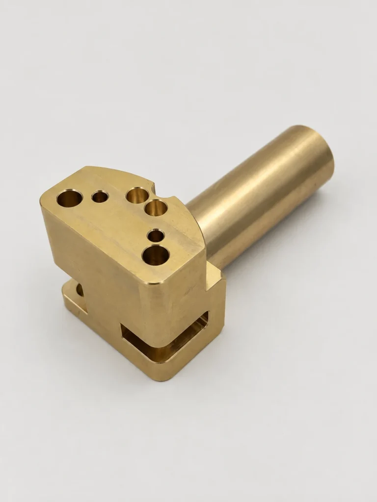
Compare press fit and slip fit dowel pins using both tolerance ranges
A press fit provides retention through interference between the pin and receiving hole. A slip fit provides clearance for insertion and removal. In an assembly with a pin retained in one component and a removable mating component, the two receiving holes can require different fits even though they share the same nominal pin diameter.
Review the permitted limits of the pin as well as the hole. Nominal diameter alone cannot establish whether the result will be clearance, interference or a transition between the two. A hole tolerance designation such as H7 must be interpreted at the stated nominal size and considered together with the mating pin tolerance.
For guaranteed clearance across the specified size ranges, the smallest permitted hole must remain larger than the largest permitted pin. For guaranteed interference, the smallest permitted pin must remain larger than the largest permitted hole. When the ranges overlap, some permitted combinations may have clearance and others interference.
The following hypothetical limits illustrate the comparison. All values are in millimetres and serve only to explain the arithmetic; the customer’s design establishes the actual limits.
In the clearance example, comparing the smallest hole with the largest pin gives the minimum clearance. Comparing the largest hole with the smallest pin gives the maximum. Both ends matter: sufficient clearance helps insertion, while excessive clearance can reduce locating repeatability.
For an interference fit, retention and installation force also depend on the host material, wall thickness, engagement, surface condition and pin design. SPIROL’s straight pin application guidance explains why recommended press-fit hole size depends on the host material for its straight pins. A recommendation for one pin product is not a general interference allowance for every ground dowel or machined component.
Keep hole diameter and hole position as separate requirements
Dowel pin hole tolerance includes more than diameter. The hole must be located relative to the surfaces and features that establish the assembly. A correctly sized hole can be displaced, tilted or inconsistent with the mating pattern.
Define the datum references around the actual seating and locating arrangement. If a plate rests against a mounting face, that face influences how the component sits when the pin enters. If an edge, bore or second locating feature establishes orientation, the drawing should communicate that relationship as well.
A center-to-center distance between two holes answers one question about the pattern. It does not necessarily define where the complete pattern sits relative to a mounting edge or another functional feature. Two holes can have the correct separation while the whole pattern is shifted.
Where the drawing uses a position tolerance, interpret its datum references, tolerance-zone form and any material condition modifiers under the applicable drawing standard. A coordinate result for an individual hole is not automatically the same as a position result evaluated from the required datum system.
If the intended assembly relationship is unclear, resolve it before choosing a machining or inspection setup. SAMSHION’s GD&T guide for CNC machining discusses the information needed to connect feature tolerances with the manufacturing review.
Understand why two dowels can bind even when each hole passes a size check
A single hole may accept its intended pin, yet a second hole may fail to engage when both pins must enter together. The available clearance has to accommodate the relative location and orientation of the complete pattern. Checking the two diameters separately leaves that relationship untested.
Consider one ideal circular receiving hole around one fixed circular pin, with parallel axes and no other assembly constraints. A diametral clearance of 0.020 mm gives a radial gap of 0.010 mm. In this simplified case, the receiving hole can move only 0.010 mm away from the pin center before contact occurs. Treating the full diametral clearance as permissible center displacement would overstate the available movement.
A real two-pin assembly adds the second pin, the mating faces, manufacturing variation and possible axis tilt. An error at one hole may consume clearance needed at the other. Longer engagement can also make angular misalignment more significant. The simplified single-hole example therefore explains a limit rather than predicting a complete assembly’s acceptance.
Some locating designs use one round pin and one relieved diamond pin to control position and orientation while avoiding redundant constraint in one direction. Carr Lane explains this arrangement in its diamond pin locating principles. The relief direction and mating geometry belong in the approved design; a supplier should not replace a specified round pin or enlarge a locating hole to make an assembly fit without a drawing change.
Review the two components together when assembly alignment matters. The related prototype tolerance stack-up guide explains why acceptable individual dimensions can still leave a problem at the interface.
Select the machining route for the diameter and tolerance
At SAMSHION, the hole diameter and specified tolerance guide process selection. The usable depth, material, accessibility and relationship to the locating datums also affect the practical route. A blanket instruction to ream every dowel hole can add an operation without resolving the requirement that actually controls the part.
Drilling creates the initial opening efficiently. Its suitability as the final operation depends on the required size, geometry and surface condition. Tool runout, entry conditions and the prepared surface can affect where the hole forms, so the initial hole needs to support any subsequent finishing operation.
Reaming can finish a prepared hole to the required size and surface condition on suitable geometry. The pre-hole must leave appropriate stock for the chosen tool. Too little allowance can produce rubbing, while excessive allowance changes the cutting load. Select the allowance for the tool, diameter and material rather than applying one fixed value to all locating holes.
A reamer generally follows the prepared hole and should not be treated as a reliable way to relocate a significantly misplaced axis. If location needs correction, review the remaining stock and access for a suitable boring or milling operation. Material removal cannot restore a hole that is already too large.
Boring and circular interpolation can be considered where their tool access and process capability suit the feature. For a small hole, available tooling can restrict the choice. For a deeper bore, tool reach and stiffness can become important. For interpolation, cutter condition and machine motion need to support the required size and form.
The route should be judged by the finished requirement. Specifying a familiar operation name does not establish that the hole meets the drawing. The process plan and final inspection need to address the same controlled characteristics.
Preserve the datum relationship through successive setups
Locating holes and their mating face may be produced in different operations. Each setup must carry the drawing’s reference relationships into the next operation. A hole made accurately relative to one temporary gripping surface may still be wrong relative to the final assembly datum.
Where practical, machining related features from a common stable setup can reduce transfers. Other geometries require turning the component over or machining several sides. In those cases, the locating surfaces, support and transfer method need to preserve the required relationships.
Check that clamps do not distort a flexible section or prevent the part from seating as intended. A thin plate can behave differently while clamped and after release. The condition used for acceptance should follow the drawing, including any specified restraint or support.
SAMSHION’s datum transfer guide provides the corresponding setup considerations. For locating holes, the important connection is between the final bore axis, the mating face and the features used to position the component in service.
Specify usable hole depth and a controlled entry
Blind dowel holes need a clear definition of usable full-diameter depth. The total depth reached by a drill tip is different from the cylindrical length available for pin engagement. A tapered drill bottom or tool lead can reduce that usable length.
Review the intended insertion depth and any shoulder, stop or protrusion requirement. A pin bottoming before the mating faces seat can resemble a fit problem even when the diameter is correct. The drawing should establish the relevant depth reference and the intended assembled condition.
A controlled hole-mouth chamfer can help entry and remove a sharp edge. An excessive chamfer can shorten effective engagement or remove more material than the design allows. Define its size where it matters and keep it distinct from a general instruction to deburr.
For blind press-fit arrangements, the design may also need to account for trapped air, residual liquid and installation access. The appropriate solution depends on the pin and host geometry. These details should be reviewed with the assembly design rather than addressed by an unapproved change during machining.
Cross holes and interrupted surfaces can introduce burrs inside a locating bore. Deburring must remove the obstruction while preserving the required diameter and edge geometry. Our deburring and edge inspection guide covers the related controls.
Check the final material and surface treatment condition
Hole size and position should be specified for the condition in which the component will be accepted. Heat treatment or a subsequent surface process can affect the dimensions or surface condition of an already machined bore. The required final state belongs in the process review.
For treated aluminum parts, establish whether the locating bore is coated, masked or finished afterward. Coating inside a precision bore can affect the available clearance. The amount depends on the specified process and its behavior, so a supplier needs a defined finishing requirement rather than a generic instruction to add allowance.
If the customer requires a masked hole, the masking boundary and adjacent appearance or corrosion requirements may also matter. If machining after finishing is specified, the exposed surface and subsequent inspection condition need to be understood. SAMSHION’s aluminum anodizing allowance guide provides the relevant finishing context.
Material selection also affects an interference-fit design. A thin aluminum wall, a steel block and an engineering plastic can respond differently to installation loading. The designer establishes the required joint behavior; machining to a tighter hole does not automatically solve retention, deformation or removal concerns.
Use pin gauges for the size question they can answer
Pin gauges are useful for checking whether a suitable cylindrical gauge enters a hole under the defined inspection conditions. At SAMSHION, we use them for applicable bore size checks. Starrett describes this use in its pin gauge overview.
Select the gauge sizes and procedure to match the hole limits and inspection plan. Gauge tolerance, condition and the accessible length affect the interpretation. A pin set with coarse increments may not resolve a very narrow hole tolerance adequately.
Clean the gauge and hole, and remove the specified burrs before evaluating entry. Forcing a gauge through resistance can obscure the condition or damage the surface. If entry changes with depth, investigate the hole and its access instead of recording only the first point of entry.
A single pin that enters does not establish both diameter limits. Nor does it independently report taper, roundness, roughness, position or axis direction. Depending on the requirement, limit gauging or another suitable measurement may be needed to characterize the bore more fully.
Keep the size result distinct from the assembly fit. A gauge tests the feature for which it was selected. A production dowel has its own diameter limits, surface condition and engagement, and a mating pattern introduces additional geometric requirements.
Use CMM inspection for the specified hole relationships
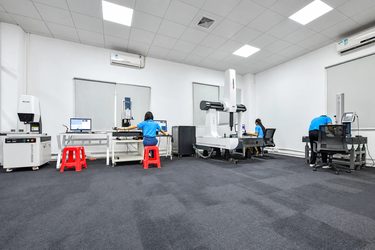
CMM inspection can evaluate locating hole positions relative to the drawing’s datum references when access, probing strategy and measurement capability suit the requirement. The alignment used for the report must represent the required datum system.
Plan how the hole axis will be established. Points near the mouth alone may not adequately describe the direction of a longer bore. Appropriate sampling at accessible depths helps evaluate the characteristic in question. Small diameters or restricted blind holes can require another suitable method or an agreed inspection arrangement.
Report the relevant hole relationships alongside the size results. Depending on the drawing, these can include position, separation, orientation to a mating face or another specified geometric requirement. Do not treat a center distance as a substitute for every other pattern requirement.
The report should identify the component revision and the characteristics actually checked. SAMSHION’s CNC inspection reporting guide explains the distinction between measurement results and other conformity documents.
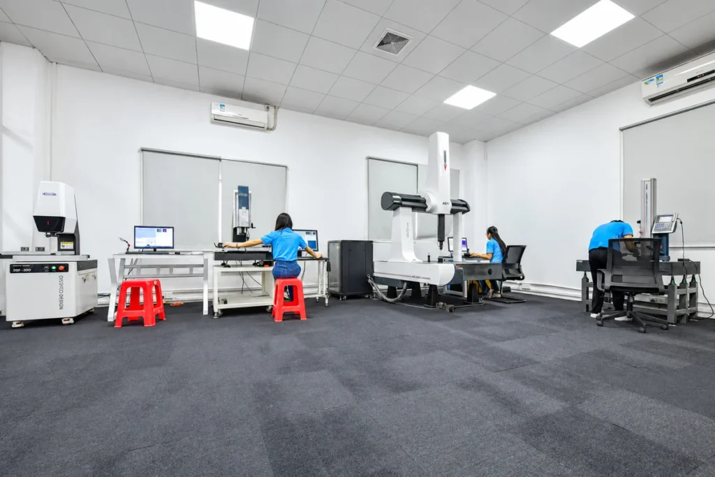
Define assembly verification when it is required
Component inspection and assembly verification answer related questions. A component report evaluates the specified drawing characteristics. A trial with a particular mating part evaluates that combination under the trial conditions. Neither result should silently change the acceptance basis for the other.
If the customer requires a pin insertion or mating-part trial, identify the pin specification, mating component revision, engagement and acceptance criteria before production. Clarify whether the trial must demonstrate insertion, seating, removal or repeatable location. An undefined instruction to check fit leaves those decisions unresolved.
A successful trial with one selected mating part does not establish interchangeability across every permitted size combination. Conversely, an assembly that binds may contain a nonconforming mating part, a burr, an incorrect pin or a geometric mismatch. Review the actual conditions before changing the machined hole.
Our prototype assembly checks guide addresses the broader coordination of mating components. For dowel holes, specify any trial as an additional agreed task alongside the component drawing inspection.
Include the locating hole requirements in the RFQ
Send the controlled drawing and CAD model with the assembly information needed to review the locating function. Useful inputs include the following where applicable.
- The locating holes and the mating pin specification, including permitted pin diameter limits.
- Hole size, usable depth, entry chamfer and required surface condition.
- Datum references, hole pattern requirements and specified geometric tolerances.
- Material grade and the required condition after heat treatment or surface finishing.
- Whether a pin is retained permanently or a mating component must be removable.
- Required inspection characteristics and whether numerical results or limit-gauge records are needed.
- Any specified mating-part trial, installation or removal requirement.
Identify the controlling documents if the assembly information and component drawing differ. A photograph can help show the intended arrangement, while the dimensions, tolerances and acceptance requirements need a controlled definition.
Frequently asked questions about dowel pin holes
Are all dowel pin holes made by reaming
The route depends on the hole diameter and tolerance, along with depth, access and material. Reaming is one possible finishing method. Boring or interpolation may suit other requirements. The finished feature must meet the drawing regardless of the selected operation.
Does an H7 hole guarantee a slip fit
The hole designation must be considered with nominal diameter and the mating pin’s permitted size. The clearance or interference depends on both tolerance ranges. Hole form, position and surface condition also affect the practical result.
Can a pin gauge confirm hole position
A pin gauge used for an individual bore size check does not establish its location relative to the drawing datums. Position needs an appropriate geometric inspection. A designed functional gauge is a different inspection arrangement with its own requirements.
Why do two correctly sized dowel holes fail to align
The pattern may be misplaced, have an incorrect separation or contain tilted axes. The mating component or pins may also differ from the intended specification. Inspect the pattern and mating conditions rather than increasing the hole diameter immediately.
Is drilled depth the same as usable dowel engagement
For a blind hole, the drill point and any unfinished lead can reduce the full-diameter length. Specify and check the usable depth required by the pin. The assembly must also be able to seat without unintended bottom contact.
Does a successful trial establish interchangeability
A trial confirms the tested combination under its defined conditions. Interchangeability requires evaluation of the permitted component and pin variation. The drawing requirements and any agreed assembly verification should reflect that objective.
Send the drawing and mating pin requirements for review
Dowel pin holes work as part of a locating arrangement. Reviewing the pin limits, bore size, hole pattern and final material condition together gives manufacturing and inspection a common basis. At SAMSHION, the customer’s drawing guides acceptance, and the hole diameter and tolerance guide the choice of machining method.
Send your drawing, CAD model, quantity and mating pin details to SAMSHION for a manufacturing review. Include any required assembly verification so the quotation can address the component inspection and additional trial on a defined basis.