Introduction
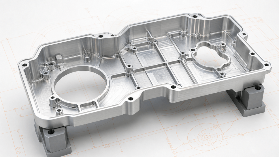
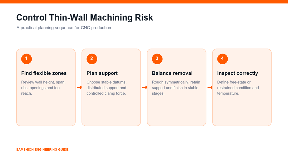
Thin-wall parts reduce mass and package components efficiently, but they are not simply ordinary machined parts with less material. As a wall becomes more flexible, cutting force, clamping pressure, heat and residual stress can move it during or after machining. A wall may measure correctly while clamped and change after release.
Successful thin-wall CNC machining therefore requires a connected plan covering geometry, stock, process sequence, tool access, workholding and inspection. This guide explains the main failure mechanisms and the questions a designer should answer before requesting a quote. For general process capabilities, see our CNC machining services.
What Counts as a Thin Wall?
There is no single wall-thickness number that separates easy and difficult parts. Risk depends on the ratio between wall height, unsupported span and thickness, plus material stiffness, pocket depth, tool reach, tolerance, surface finish and clamping strategy. A short supported rib can be stable at a thickness that would be risky for a tall open wall.
Instead of asking only “How thin can this be?”, evaluate:
- How far is the wall from a rib, corner or boss?
- Can both sides be machined with balanced material removal?
- Is the wall accessible with a short, rigid cutter?
- Which surfaces can support or locate the part without distortion?
- Must the tolerance apply in the free state or assembled state?
- Will anodizing, heat treatment or temperature change affect the result?
Why Thin Walls Move During CNC Machining
Elastic Deflection Under Cutting Force
The cutter pushes on the workpiece. A rigid section moves very little, while a slender wall bends away from the tool and may spring back after the edge passes. The result can be taper, waviness, oversize or undersize conditions and inconsistent surface finish. Tool deflection can occur at the same time, so the final error is the interaction of tool, wall, spindle, holder and fixture stiffness.
Distortion From Residual Stress
Rolled plate, extruded stock, forgings and heat-treated material can contain residual stress. Removing material changes the balance of that stress and the part may bow or twist. Symmetrical stock removal, stress-relieved material, intermediate unclamping or a rough-and-rest sequence may reduce risk, but the correct plan depends on geometry and material history.
For aluminum applications, our 6061 aluminum CNC machining guide explains why temper and stock condition matter alongside nominal alloy chemistry.
Clamping Distortion
Clamps can force a flexible part flat against the fixture. If inspection is performed before release, the part may appear correct even though it returns to a different shape afterward. Locating and clamping should constrain the required degrees of freedom without imposing unnecessary bending.
Heat and Thermal Expansion
Cutting heat, coolant temperature and room conditions can change dimensions. Thin sections respond quickly because they have little thermal mass. Inspection temperature and stabilization time become more important as tolerance tightens. NIST identifies 20 degrees Celsius as the reference temperature for industrial dimensional measurements; actual acceptance still depends on the drawing, material and agreed procedure.
Geometry Changes That Improve Stability
Use Ribs, Returns and Closed Sections
A rib, flange or return can increase stiffness without making the entire part heavy. Closed or partially closed sections usually resist bending better than long unsupported plates. Place reinforcement along load paths and around interfaces rather than adding decorative material that creates difficult pockets.
Make Transitions Gradual
Abrupt changes between thick bosses and thin panels concentrate stress and complicate material removal. Use manufacturable fillets and gradual transitions where function permits. Internal corner radii should accommodate available end mills. Our CNC milling services page explains why cutter diameter and access shape internal geometry.
Preserve Support Until Late in the Process
Temporary tabs, sacrificial webs or extra stock can support flexible regions during roughing and semi-finishing. These supports are removed after the main geometry becomes stable. This approach adds operations, so it should be planned rather than improvised after chatter begins.
Do Not Apply Tight Tolerance Everywhere
Use critical tolerances only on surfaces that control fit, sealing, motion or alignment. A broad profile or flatness requirement across a flexible cover may demand special fixturing and free-state inspection. Connect datums and tolerances to assembly function through the design for manufacturability guide.
Workholding Strategies for Thin Parts
Strategy | Useful when | Watch for |
Machinable soft jaws | The part has repeatable external support surfaces | Jaw pressure and local marking |
Vacuum fixture | A broad, reasonably sealed surface is available | Seal integrity, holding force and cutting direction |
Adhesive or wax support | Very thin plates need distributed backing | Removal method, cleanliness and temperature |
Sacrificial carrier | The part can remain attached to a rigid frame | Extra material and separation operation |
Custom nests and supports | Complex housings require local support | Access for cutters, chips and inspection |
Support should be close to the cutting zone when possible, but it must not block the toolpath or trap chips. Clamping force should be repeatable and no greater than necessary. If the fixture establishes an artificial shape, the drawing should state whether dimensions apply while restrained or after release.
Tool and Toolpath Decisions
Prefer a Short, Rigid Tool
Long reach magnifies tool deflection and vibration. Increase internal corner radii or open access where possible so a larger, shorter cutter can be used. Toolholders, runout and spindle condition also matter; replacing geometry alone cannot compensate for an unstable setup.
Rough With Balanced Stock
Removing most material from one side first can unbalance stress. A staged process may alternate sides or leave uniform finishing stock. Some parts benefit from roughing, unclamping, stabilization and a separate finishing setup. The manufacturing engineer should decide the sequence from the actual stock and geometry.
Control Radial Engagement and Cutting Direction
Low-force toolpaths and consistent engagement can reduce shock on flexible walls. Climb or conventional direction, step-down, radial engagement, flute count and feed per tooth must suit the specific tool and material. Avoid copying generic cutting parameters without considering wall support and machine dynamics.
Finish in Controlled Passes
Very light rubbing passes can produce heat and unstable size, while an excessive finishing cut can push the wall away. The finishing allowance must be large enough for the cutter to work properly but small enough to limit load. Trial cuts and in-process measurement may be required for demanding geometries.
Chatter, Squeal and Poor Surface Finish
Chatter is a system-level instability, not simply a spindle-speed problem. Check tool overhang, wall support, fixture contact, cutter engagement, runout, holder condition and toolpath transitions. A visible repeating pattern may come from vibration, while smeared or torn material can indicate rubbing, built-up edge or chip recutting.
Corrective actions can include changing spindle speed away from a resonant zone, shortening the tool, adding support, changing flute engagement, improving chip evacuation or revising the sequence. Surface requirements should be specified with function in mind; our CNC machining surface finish guide separates measured roughness from visual appearance and coating preparation.
Inspection Planning for Flexible Parts
Thin parts need a defined inspection state. A flexible cover measured on a granite plate, in a fixture and in its final assembly can produce different results. The drawing or quality plan should state free-state versus restrained inspection, datum simulation, stabilization conditions and any assembly torque used for verification.
A CMM can evaluate profile, position and relationships, but probe force and fixturing still matter. Optical or scanning methods may help with delicate surfaces. The article CNC machining inspection: CMM, FAI and dimensional reports explains how to choose evidence for each characteristic.
Practical Risk Review Before Quoting
Question | Why it matters |
What is the unsupported wall height and span? | Stiffness depends on geometry, not thickness alone |
Which surfaces are functional? | Directs tolerance, support and inspection effort |
What stock form and temper are required? | Influences residual stress and material response |
Can the part stay on a sacrificial frame? | May simplify support during machining |
Is cosmetic finish required? | Changes handling, toolpath and secondary operations |
What quantity is planned? | Determines whether dedicated fixtures are economical |
DFM Checklist for Thin-Wall Parts
- Identify functional surfaces and relax noncritical tolerances.
- Add ribs, returns or closed sections where the load path allows.
- Increase internal radii to permit shorter, stronger tools.
- Provide stable locating and clamping surfaces.
- Consider stock condition and balanced material removal.
- Define free-state or restrained inspection.
- Review finishing and thermal effects.
- Share annual volume so prototype and production fixtures can be compared.
Request a Thin-Wall DFM Review
Send the 3D CAD model, 2D drawing, material and temper, quantity, finish and assembly conditions. Mark the surfaces that control sealing, alignment or appearance. Samshion can review wall risk, access, stock, workholding, sequence and inspection before machining. Upload your CAD files for a quote.
Frequently Asked Questions
What is the minimum wall thickness for CNC machining?
There is no universal value. Material, wall height, unsupported span, tool reach, tolerance, surface finish and fixture support must be evaluated together.
Why does a part change shape after it leaves the fixture?
Clamping may elastically flatten the part, or material removal may release residual stress. When the clamp is removed, the part reaches a new equilibrium shape.
Can more clamps prevent thin-wall vibration?
Not automatically. More contact can improve support, but excessive or poorly located force can distort the part. Distributed, repeatable support is more important than clamp count.
Is aluminum always easy to machine in thin sections?
Aluminum cuts efficiently, but thin aluminum walls can still deflect or distort. Alloy, temper, stock history, geometry and process sequence remain important.
Should thin parts be inspected while clamped?
Only when the specification or functional condition calls for restrained inspection. Otherwise, free-state results may be the relevant acceptance condition.