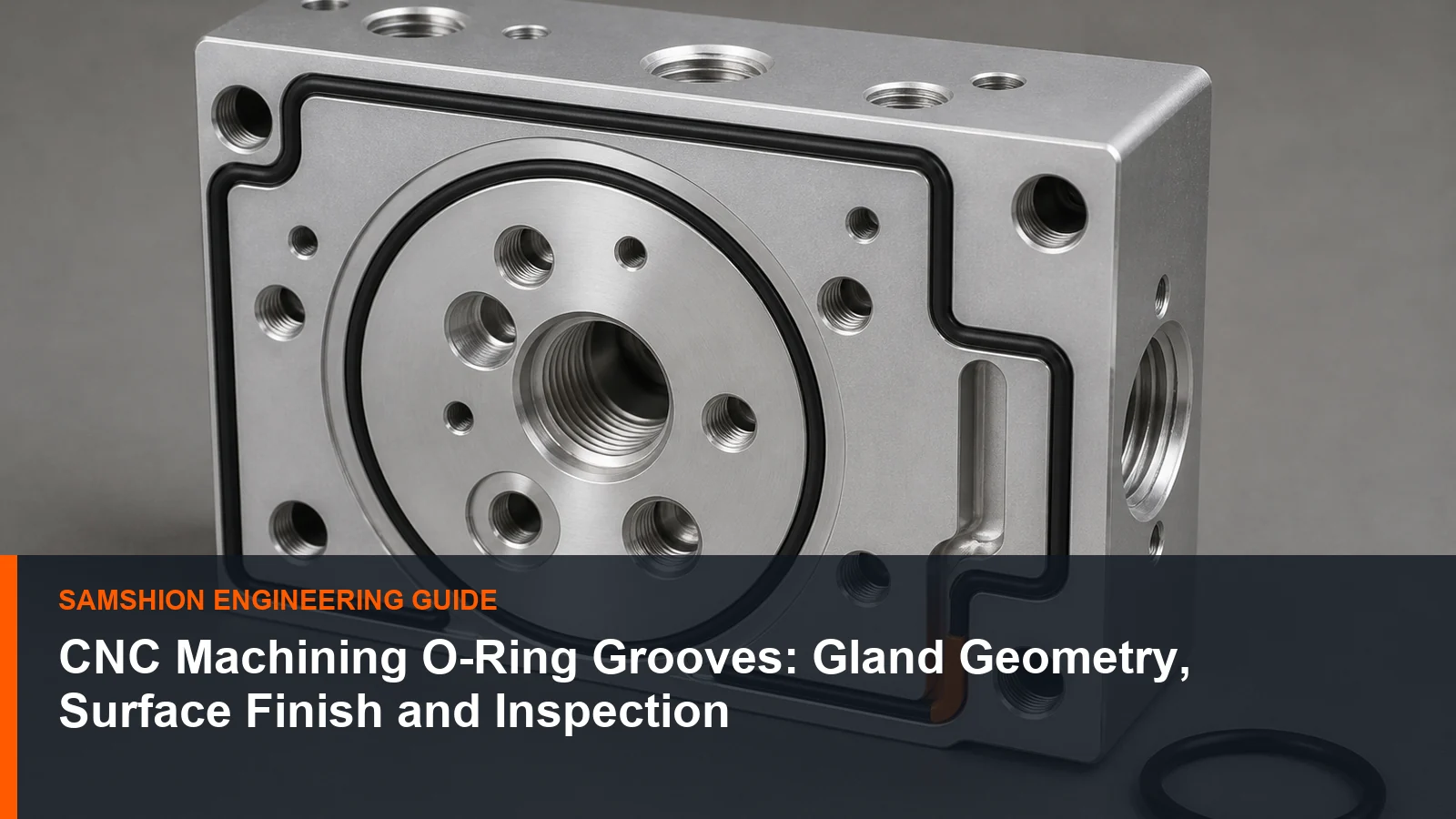
An O-ring does not seal because a groove merely exists. The gland must provide the intended compression while leaving appropriate volume for deformation, pressure and material behavior. Static face seals, radial seals and dynamic applications do not share one universal geometry.
Machining begins only after the seal application and gland calculation are defined. The supplier’s job is then to preserve width, depth, position, edge condition and surface texture through machining, coating and inspection.
Scope, Search Intent and Technical Boundary
This article focuses on machining and inspecting O-ring glands after the seal design has been selected. It does not attempt to replace a seal manufacturer’s application design handbook.
Apply the guidance to quotation and first-article planning for CNC machining O-ring grooves; do not treat illustrative values as guaranteed tolerances. For broader geometry and specification guidance, use the design for manufacturability guide alongside this feature-level discussion.
Key Takeaways
- Identify the seal application before selecting gland dimensions.
- Dimension width and depth from stable functional datums.
- Protect the O-ring with suitable entry edges.
- Control toolpath witness marks and surface lay in the sealing path.
- Account for anodize, plating or other finish in final groove geometry.
Start with the Seal Application
Static face, piston, rod, reciprocating and rotary seals need different design considerations. Use the seal manufacturer’s handbook. Select the gland from a recognized seal-design source such as the Parker O-Ring Handbook ORD 5700 and then translate the chosen application requirements into the controlled part drawing.
Translate Gland Requirements into a Drawing
State width, depth, diameter or path, corner condition, finish and datums clearly.
Machine Continuous and Complex Grooves
Stable interpolation, cutter reach and entry strategy control width and witness marks. For the corresponding manufacturing decision and capability context, consult SAMSHION’s CNC milling services.
Allow for Coatings and Surface Treatments
Coating changes groove dimensions and edge condition. Inspect after the final specified finish. For the corresponding manufacturing decision and capability context, consult SAMSHION’s surface finishing services.
Verify the Finished Gland
Measure width, depth, path position, texture and local defects at more than one location. For the corresponding manufacturing decision and capability context, consult SAMSHION’s CNC machining surface finish options.
Engineering Variables to Confirm Before Quotation
Static face, radial piston, rod, reciprocating or rotary application
For CNC machining O-ring grooves, static face, radial piston, rod, reciprocating or rotary application requires an explicit engineering decision. Use this requirement to frame the first technical review. Ask which function depends on it, which datum or material state establishes it, and at what production stage it will be accepted. The decision can move a feature from a routine check to a controlled first-article characteristic. Record the agreed interpretation beside the revision so later orders do not reopen the same ambiguity.
O-ring cross-section and allowable compression
For CNC machining O-ring grooves, O-ring cross-section and allowable compression requires an explicit engineering decision. Use this requirement to frame the first technical review. Ask which function depends on it, which datum or material state establishes it, and at what production stage it will be accepted. It influences whether the feature is produced and accepted before or after secondary finishing. Where two documents disagree, obtain a controlled clarification before releasing material. Available grades, stock forms and supplied conditions can be cross-checked against the CNC machining materials before quotation.
Gland width for volume swell and pressure
For CNC machining O-ring grooves, gland width for volume swell and pressure requires an explicit engineering decision. Use this requirement to frame the first technical review. Ask which function depends on it, which datum or material state establishes it, and at what production stage it will be accepted. The result governs how much process evidence is needed to support the quotation. Tie any relaxation to the actual function rather than to a generic shop capability statement.
Corner radius and entry-edge protection
For CNC machining O-ring grooves, corner radius and entry-edge protection requires an explicit engineering decision. Do not allow a default title-block tolerance to answer this question indirectly. Ask which function depends on it, which datum or material state establishes it, and at what production stage it will be accepted. The result governs how much process evidence is needed to support the quotation. Record the agreed interpretation beside the revision so later orders do not reopen the same ambiguity.
Surface texture and lay on the sealing path
For CNC machining O-ring grooves, surface texture and lay on the sealing path requires an explicit engineering decision. Treat this as an RFQ input, not a shop-floor surprise. Ask which function depends on it, which datum or material state establishes it, and at what production stage it will be accepted. It may determine whether a flexible prototype route remains suitable for repeat production. A written assumption lets the buyer compare suppliers on an equivalent technical basis.
Coating or anodize thickness after machining
For CNC machining O-ring grooves, coating or anodize thickness after machining requires an explicit engineering decision. Use this requirement to frame the first technical review. Ask which function depends on it, which datum or material state establishes it, and at what production stage it will be accepted. Its interpretation changes datum selection, setup count and verification effort. A written assumption lets the buyer compare suppliers on an equivalent technical basis.
Failure Modes and Root-Cause Diagnosis
The groove depth is measured from the wrong reference surface
A characteristic failure for CNC machining O-ring grooves occurs when the groove depth is measured from the wrong reference surface. The observation is evidence, not yet a root cause. Evaluate material behavior, support, cutter condition, programmed sequence and the measurement alignment as separate hypotheses. Use a controlled trial that changes one suspected mechanism while holding the remaining variables constant. Do not hide the symptom with manual blending unless the drawing explicitly permits that edge condition.
A coating reduces gland volume more than the design allowed
A characteristic failure for CNC machining O-ring grooves occurs when a coating reduces gland volume more than the design allowed. The observation is evidence, not yet a root cause. Evaluate material behavior, support, cutter condition, programmed sequence and the measurement alignment as separate hypotheses. Check whether the indication follows the cutter, the setup, the material lot or the inspection alignment. Document the evidence that ruled each competing cause in or out.
A sharp entry edge cuts the seal during assembly
A characteristic failure for CNC machining O-ring grooves occurs when a sharp entry edge cuts the seal during assembly. The observation is evidence, not yet a root cause. Evaluate material behavior, support, cutter condition, programmed sequence and the measurement alignment as separate hypotheses. Use a controlled trial that changes one suspected mechanism while holding the remaining variables constant. Do not hide the symptom with manual blending unless the drawing explicitly permits that edge condition.
Circular interpolation leaves a witness mark across the sealing path
A characteristic failure for CNC machining O-ring grooves occurs when circular interpolation leaves a witness mark across the sealing path. The observation is evidence, not yet a root cause. Evaluate material behavior, support, cutter condition, programmed sequence and the measurement alignment as separate hypotheses. Map the symptom by feature location, tool life and operation sequence instead of averaging it into one result. If the cause remains uncertain, contain the lot and expand the trial before releasing more material.
Process Controls for a Repeatable Result
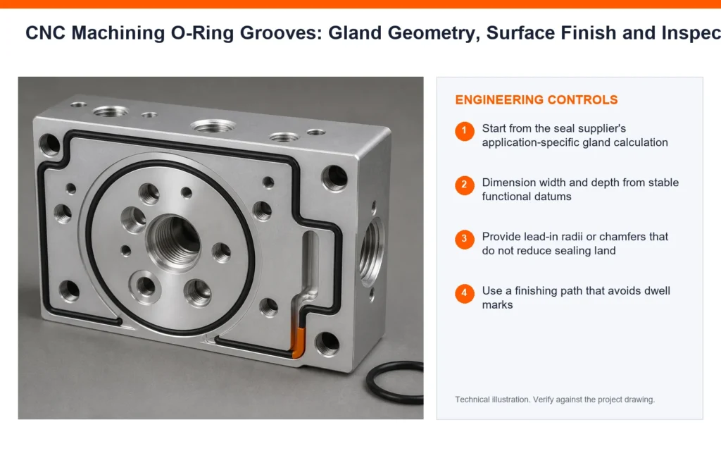
Start from the seal supplier's application-specific gland calculation
A process plan for CNC machining O-ring grooves can control this risk by choosing to start from the seal supplier’s application-specific gland calculation. The action is useful only when it targets a named source of variation. Before release, consider access, local stiffness, heat flow and the acceptance condition of neighboring features. Use a short prototype trial first; formalize fixture, sampling and tool-life rules for repeat orders. If it changes a controlled requirement, customer approval comes before production release. The applicable production route and process controls are outlined in SAMSHION’s CNC production machining.
Dimension width and depth from stable functional datums
A process plan for CNC machining O-ring grooves can control this risk by choosing to dimension width and depth from stable functional datums. The action is useful only when it targets a named source of variation. Before release, consider access, local stiffness, heat flow and the acceptance condition of neighboring features. Link the method to the part revision, program revision and inspection revision. If it changes a controlled requirement, customer approval comes before production release.
Provide lead-in radii or chamfers that do not reduce sealing land
A process plan for CNC machining O-ring grooves can control this risk by choosing to provide lead-in radii or chamfers that do not reduce sealing land. The action is useful only when it targets a named source of variation. Before release, consider access, local stiffness, heat flow and the acceptance condition of neighboring features. Use a short prototype trial first; formalize fixture, sampling and tool-life rules for repeat orders. The inspector must evaluate the same condition the operator is controlling.
Use a finishing path that avoids dwell marks
A process plan for CNC machining O-ring grooves can control this risk by choosing to use a finishing path that avoids dwell marks. The action is useful only when it targets a named source of variation. Before release, consider access, local stiffness, heat flow and the acceptance condition of neighboring features. Review adjacent walls, threads, sealing lands and datums for unintended consequences. The inspector must evaluate the same condition the operator is controlling.
Account for plating or anodize on all groove surfaces
A process plan for CNC machining O-ring grooves can control this risk by choosing to account for plating or anodize on all groove surfaces. The action is useful only when it targets a named source of variation. Before release, consider access, local stiffness, heat flow and the acceptance condition of neighboring features. Link the method to the part revision, program revision and inspection revision. Repeat production should not depend on an operator remembering an undocumented exception.
Inspect the actual gland rather than relying on tool diameter alone
A process plan for CNC machining O-ring grooves can control this risk by choosing to inspect the actual gland rather than relying on tool diameter alone. The action is useful only when it targets a named source of variation. Before release, consider access, local stiffness, heat flow and the acceptance condition of neighboring features. Verify that the method remains stable after tool change, unclamping or finishing. If it changes a controlled requirement, customer approval comes before production release.
Inspection Strategy and Acceptance Evidence
Groove width and depth at several locations
Inspection of CNC machining O-ring grooves should explicitly address groove width and depth at several locations. First define the characteristic, datum reference and part condition represented by the result. Build the datum alignment exactly as defined on the controlled drawing. When results disagree, compare alignment, force, temperature and feature definition before averaging values.
Diameter or perimeter position relative to ports
Inspection of CNC machining O-ring grooves should explicitly address diameter or perimeter position relative to ports. First define the characteristic, datum reference and part condition represented by the result. Build the datum alignment exactly as defined on the controlled drawing. Identify whether each result is measured, visually verified or supported only by material documentation.
Surface texture and localized tool marks
Inspection of CNC machining O-ring grooves should explicitly address surface texture and localized tool marks. First define the characteristic, datum reference and part condition represented by the result. Sample the locations and depths where process behavior can genuinely change. Identify whether each result is measured, visually verified or supported only by material documentation.
Corner radii and entry-edge condition
Inspection of CNC machining O-ring grooves should explicitly address corner radii and entry-edge condition. First define the characteristic, datum reference and part condition represented by the result. Build the datum alignment exactly as defined on the controlled drawing. Agree the acceptance method before machining when a supplier and customer could reasonably measure differently. The available verification and reporting workflow is summarized in SAMSHION’s quality assurance.
Coating thickness contribution to final gland geometry
Inspection of CNC machining O-ring grooves should explicitly address coating thickness contribution to final gland geometry. First define the characteristic, datum reference and part condition represented by the result. Correlate shop-floor and final-inspection methods before using either for acceptance. Report nominal, limits and actual result; do not substitute a certificate statement for measured data.
Cost, Lead Time and Quotation Transparency
Continuous versus complex perimeter groove
In a quotation for CNC machining O-ring grooves, continuous versus complex perimeter groove can influence both lead time and total manufacturing cost. Secondary finishing and final-state inspection can make this more influential than raw cycle time. Compare flexible and dedicated production routes when order volume could justify either.
Small cutter reach
In a quotation for CNC machining O-ring grooves, small cutter reach can influence both lead time and total manufacturing cost. Secondary finishing and final-state inspection can make this more influential than raw cycle time. Do not reduce price by silently omitting the requested acceptance evidence.
Surface-finish requirement
In a quotation for CNC machining O-ring grooves, surface-finish requirement can influence both lead time and total manufacturing cost. A prototype route may be economical once but unsuitable for a repeating order. State the assumed interpretation, included records and conditions that would trigger requotation.
Special inspection access and coating reinspection
In a quotation for CNC machining O-ring grooves, special inspection access and coating reinspection can influence both lead time and total manufacturing cost. It can add material preparation, a dedicated cutter or a separate verification step. Compare flexible and dedicated production routes when order volume could justify either.
A Practical Engineering Review Sequence
Start with the function protected by static face, radial piston, rod, reciprocating or rotary application. Mark the related datums, interfaces and delivered-state requirements on the controlled drawing. The manufacturing review can then choose stock, setups and cutting access around that function instead of treating every dimension as equally critical.
Walk through the likely failure mechanism represented by this project: the groove depth is measured from the wrong reference surface. Decide which evidence can reveal the problem earliest and which operation can still correct it. This ordering avoids discovering a predictable condition only after finishing or final inspection.
Use the first article to validate the proposed control, including the instruction to start from the seal supplier’s application-specific gland calculation. The approval part must represent the intended material, fixture, program, secondary operations and measurement alignment. Feed the result back into the process record before releasing the balance of the order.
RFQ and DFM Checklist
- Native 3D CAD model plus a controlled 2D drawing for tolerances and notes
- Exact material grade, condition, stock preference and certification requirement
- Functional datums, mating components and genuinely critical characteristics
- Quantity, prototype or production intent, and expected repeat-order status
- Surface finish, coating, heat treatment, cleaning and marking requirements
- Inspection report, certificate, gauge or sampling requirements
- Any approved alternative geometry or process constraints
Additional Engineering Review Notes
A useful design-review exercise is to trace one requirement through the complete production route. For CNC machining O-ring grooves, examine static face, radial piston, rod, reciprocating or rotary application and ask how it could contribute to a condition in which a coating reduces gland volume more than the design allowed. One candidate action is to provide lead-in radii or chamfers that do not reduce sealing land; however, its value must be demonstrated through corner radii and entry-edge condition. Preserve enough traceability to connect the observation to material lot, setup and program revision. Also consider the commercial effect of continuous versus complex perimeter groove, because a technically sound route must be quoted with transparent assumptions. If the trial confirms the control, apply it to the remaining quantity and monitor the first repeat batch.
Use a short preproduction review to separate necessary controls from inherited drawing habits. For CNC machining O-ring grooves, examine O-ring cross-section and allowable compression and ask how it could contribute to a condition in which a sharp entry edge cuts the seal during assembly. One candidate action is to use a finishing path that avoids dwell marks; however, its value must be demonstrated through coating thickness contribution to final gland geometry. Preserve enough traceability to connect the observation to material lot, setup and program revision. Also consider the commercial effect of small cutter reach, because a technically sound route must be quoted with transparent assumptions. If the trial confirms the control, apply it to the remaining quantity and monitor the first repeat batch.
Use a short preproduction review to separate necessary controls from inherited drawing habits. For CNC machining O-ring grooves, examine gland width for volume swell and pressure and ask how it could contribute to a condition in which circular interpolation leaves a witness mark across the sealing path. One candidate action is to account for plating or anodize on all groove surfaces; however, its value must be demonstrated through groove width and depth at several locations. Check whether unclamping, cleaning or finishing changes the apparent mechanism. Also consider the commercial effect of surface-finish requirement, because a technically sound route must be quoted with transparent assumptions. Keep the approved method connected to the fixture, program and inspection revision.
The project team should test whether its acceptance rule still makes sense after all secondary operations. For CNC machining O-ring grooves, examine corner radius and entry-edge protection and ask how it could contribute to a condition in which the groove depth is measured from the wrong reference surface. One candidate action is to inspect the actual gland rather than relying on tool diameter alone; however, its value must be demonstrated through diameter or perimeter position relative to ports. Preserve enough traceability to connect the observation to material lot, setup and program revision. Also consider the commercial effect of special inspection access and coating reinspection, because a technically sound route must be quoted with transparent assumptions. Use the first article to demonstrate the relationship between the action and the protected function.
For repeat orders, convert the first-article lesson into a revision-controlled production instruction. For CNC machining O-ring grooves, examine surface texture and lay on the sealing path and ask how it could contribute to a condition in which a coating reduces gland volume more than the design allowed. One candidate action is to start from the seal supplier’s application-specific gland calculation; however, its value must be demonstrated through surface texture and localized tool marks. Record the part state and operation where the observation first becomes visible. Also consider the commercial effect of continuous versus complex perimeter groove, because a technically sound route must be quoted with transparent assumptions. The resulting instruction should name the operation, responsible role, limit and retained record.
An additional risk review should connect the drawing statement to the evidence available at final acceptance. For CNC machining O-ring grooves, examine coating or anodize thickness after machining and ask how it could contribute to a condition in which a sharp entry edge cuts the seal during assembly. One candidate action is to dimension width and depth from stable functional datums; however, its value must be demonstrated through corner radii and entry-edge condition. Identify which proposed cause would produce the observed direction and distribution of error. Also consider the commercial effect of small cutter reach, because a technically sound route must be quoted with transparent assumptions. A control that cannot be checked objectively should be rewritten before it enters the setup sheet.
Frequently Asked Questions
Can one groove size work for static and dynamic seals?
Not automatically. Application, pressure, speed, compound and lubrication change the design basis. Final acceptance depends on the stated datum, delivered state and inspection approach.
Should an O-ring groove have sharp corners?
Follow the selected gland standard and assembly requirements; entry edges generally need protection against seal damage. Confirm the project-specific answer from the controlled drawing and the actual material condition.
Does anodizing affect groove size?
Yes. The final geometry depends on coating build and whether the drawing controls pre- or post-finish dimensions. Final acceptance depends on the stated datum, delivered state and inspection approach.
Is Ra alone enough to approve a groove?
No. Local scratches, lay, waviness, width, depth and edge condition can also matter. The general rule does not replace a feasibility review of the complete geometry and acceptance method.
Get an Engineering Review
Upload the CAD model and controlled drawing for an engineering review before production. When the model and drawing are ready, use upload your seal-housing drawing and include the material, quantity, finish and inspection requirements.
For a review of CNC machining O-ring grooves, send the native CAD model, controlled drawing, material specification, quantity, finishing route and required acceptance records. SAMSHION’s engineering team can return project-specific DFM questions and documented quotation assumptions before production begins.