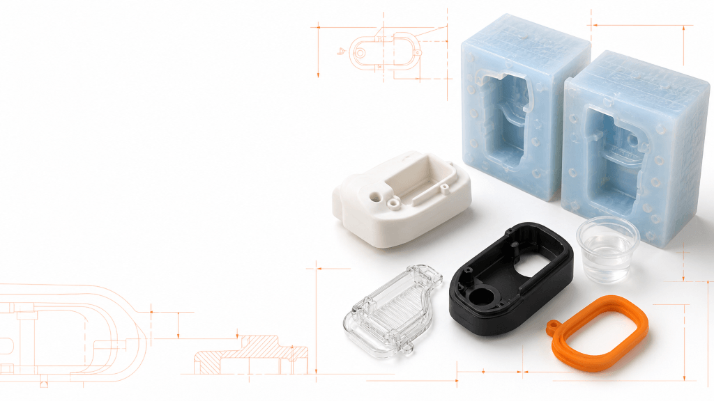
Vacuum casting, also called urethane casting or polyurethane casting, produces small batches of plastic-like parts from a silicone mold. It is often selected when a project needs more copies than direct prototyping can efficiently provide, but the quantity or design maturity does not yet justify an injection mold.
The process can reproduce fine surface detail, color, texture, transparent features and flexible components. Its main limitation is equally important: cast polyurethane is a simulation material. It does not automatically reproduce the long-term behavior of a specified injection-molding resin.
Quick answer: Vacuum casting is best suited to low-volume prototypes, appearance models, functional evaluation and early market batches when the design is reasonably stable and production-grade appearance matters more than using the final thermoplastic.
What Is Vacuum Casting?
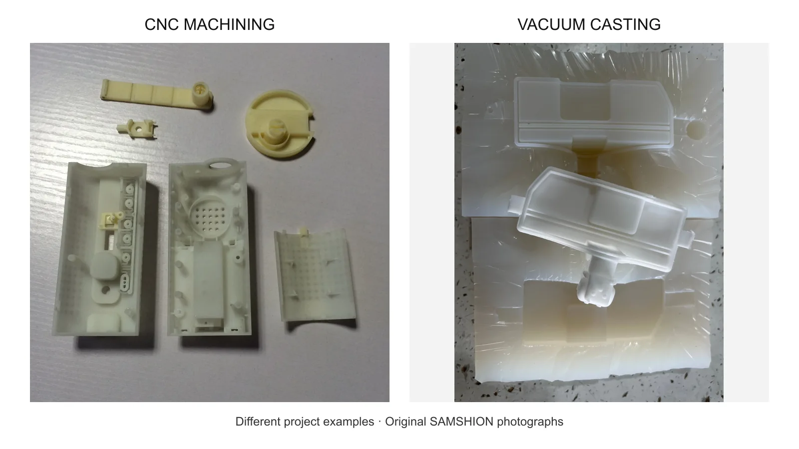
Vacuum casting begins with an accurate master pattern, normally produced by SLA 3D printing or CNC machining. Liquid silicone is poured around the prepared master and cured. The mold is opened or carefully cut, the master is removed, and gates and vents are prepared. A two-component polyurethane resin is then mixed, degassed and introduced into the silicone cavity under controlled vacuum. After curing, the part is removed, trimmed and finished.
The silicone mold is flexible, so it can release moderate undercuts and complex surfaces that would require slides or lifters in a rigid injection mold. The flexibility also means that the mold can deform, wear and change over repeated casting cycles. Dimensional capability must therefore be agreed for the actual geometry instead of presented as one universal tolerance.
Our vacuum casting services support appearance prototypes, functional evaluation and controlled low-volume production.
How the Vacuum Casting Process Works
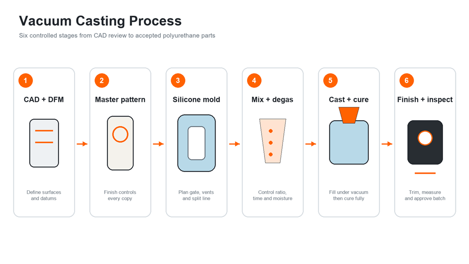
1. Review the CAD model and production requirements
The manufacturing review should identify cosmetic surfaces, critical dimensions, color, gloss, texture, material behavior, inserts, assembly interfaces and the required quantity. The team also plans the split line, gate, vents and likely trimming areas.
This review is essential because the silicone mold copies both intended detail and unintended defects. A visible layer line, sanding wave or surface pit on the master can appear on every cast part.
2. Produce and finish the master pattern
SLA is commonly used for smooth, detailed master patterns. CNC machining may be preferred for simple geometry, controlled datums or surfaces that require very high finishing quality. The master is sanded, primed, polished or textured to represent the desired finished part.
Allowances may be required for master-pattern error, silicone behavior and resin shrinkage. These allowances should be based on the selected material system and supplier experience. Applying a generic percentage to every dimension can create new errors, especially on assemblies with multiple datums.
3. Build the silicone mold
The master is positioned in a mold box with a planned feed and vent arrangement. Mixed silicone is degassed and poured around the pattern. After curing, the mold maker opens the mold along a controlled split path and removes the master without damaging the cavity.
Registration features help the mold close consistently. Gates carry resin into the cavity, vents let air escape, and risers indicate fill condition or provide a small reservoir. The placement of each feature affects bubbles, knit lines, trimming marks and surface quality.
4. Measure, mix and degas the resin
Polyurethane casting systems normally contain two reactive components. The specified mix ratio, material temperature, working time and moisture controls must be followed. Poor measurement or incomplete mixing can cause soft areas, streaks, bubbles or incomplete cure.
Vacuum removes entrained air before and during filling. It does not correct a blocked vent, resin that has already begun to gel, or a mold layout that traps air at the highest point.
5. Fill, cure and demold
The resin is introduced through the planned gate while air exits through vents. The filled mold is cured under controlled conditions according to the resin data sheet and part size. Removing a part too early can distort walls, bosses and sealing faces.
After demolding, the operator trims gates and vents. Parts may receive post-cure, sanding, polishing, painting, printing or protective coating. Transparent components require particularly careful control of the master surface, mold cleanliness, resin, cure and finishing sequence.
6. Inspect and document the batch
Inspection should start with the first acceptable casting, not after the full batch is complete. Critical dimensions, color, surface, assembly and functional requirements are checked against the approved sample or drawing. Later castings should be monitored for mold wear, flash, surface loss and dimensional drift.
Vacuum Casting Materials
Vacuum casting uses material systems designed for casting rather than pellets intended for injection molding. Suppliers often describe these resins by the production material they approximate, such as ABS-like, PP-like or rubber-like. That wording describes a target behavior, not chemical equivalence.
|
Material group |
Typical characteristics |
Common uses |
Important limitation |
|
Rigid polyurethane |
Stiff, paintable and available in several colors |
Housings, covers, brackets and appearance models |
Creep, impact and heat aging vary by resin grade |
|
Tough or impact-modified polyurethane |
Improved ductility and impact response |
Clips, protective covers and functional evaluation |
Must be tested at the intended temperature |
|
Flexible polyurethane |
Elastomer-like response in selectable hardness ranges |
Grips, seals, boots, pads and soft-touch components |
Compression set and chemical resistance are grade dependent |
|
Clear polyurethane |
Transparent or tintable after suitable finishing |
Lenses, light guides, covers and fluid-visualization models |
UV exposure, heat and moisture may change clarity over time |
|
Filled or specialty systems |
Modified stiffness, temperature response or appearance |
Technical prototypes and special demonstrations |
Processing and mold life may differ from standard resins |
Use actual technical data for tensile strength, elongation, hardness, heat resistance, color stability and cure requirements. If the final product must meet a regulatory, flammability, electrical or biocompatibility requirement, confirm whether the casting resin itself carries the required documentation.
Compare available process families in our manufacturing materials guide.
Design Guidelines for Vacuum-Cast Parts
Use practical, consistent wall thickness
Consistent walls support predictable filling, cure and dimensional control. Very thin walls can fill incompletely or tear during demolding. Thick masses can generate more reaction heat, cure unevenly and show sink or internal stress.
A starting wall range is only a discussion point. The achievable minimum depends on flow length, resin viscosity, venting, part area and mold support. Identify the thinnest local section on the drawing so the supplier can evaluate it directly.
Add radii at corners and section changes
Sharp internal corners concentrate stress and can be difficult to reproduce cleanly. Add suitable radii at wall intersections, boss roots and rib transitions. Rounded transitions also help silicone survive repeated demolding.
Plan the split line, gate and vents
Do not leave cosmetic requirements implicit. Mark Class A surfaces and areas where a gate, vent or split line is unacceptable. A hidden edge, assembly interface or noncosmetic underside is usually a better trimming location.
Vents should reach local high points and thin extremities. The gate must allow resin to fill the cavity within its working time without washing bubbles or debris onto a cosmetic surface.
Design bosses, ribs and holes deliberately
Use ribs to support walls without creating unnecessary solid sections. Bosses should have radiused roots and enough surrounding material for the expected assembly load. Deep blind holes may trap air or become difficult to demold. Some holes are more reliable when cast with a removable core, drilled after casting or represented by a pilot feature.
Use undercuts carefully
Flexible silicone allows more undercut freedom than a rigid metal mold, but every demolding action strains the cavity. A deep reverse feature, thin lip or sharp hook may shorten mold life or tear the part. For a future injection-molded product, retaining production-intent draft and split logic makes the prototype more representative.
Control text and surface detail
Raised and recessed lettering can be copied from the master, but small characters may lose clarity after primer, paint or repeated mold use. Provide vector artwork, minimum stroke requirements and the intended reading direction. Text on a separate label or printed after casting can be better for changing regulatory information.
Provide assembly datums and tolerance priorities
Dimension the features that control fit, sealing and alignment. Avoid applying a tight general tolerance to every surface. A flexible silicone mold cannot behave like a precision steel tool, especially over a large distance or through a soft unsupported section.
Tolerances, Shrinkage and Dimensional Expectations
Vacuum-cast accuracy is influenced by the CAD model, master pattern, master finishing, silicone mold, resin, cure schedule, geometry, measuring method and mold age. The dimensional chain can include:
- CAD-to-master manufacturing variation
- Master finishing and coating thickness
- Silicone cure and mold deformation
- Polyurethane reaction and cure shrinkage
- Part deformation during demolding or post-cure
- Measurement temperature and fixturing
For this reason, place realistic tolerances only on functional dimensions. Use an approved first article to establish appearance and fit. Large flat panels, long unsupported spans and flexible parts require a defined measurement fixture or free-state condition.
When the program requires the final thermoplastic and tighter repeatability across hundreds or thousands of parts, rapid tooling or production injection molding may be the more reliable path.
How Many Parts Can One Silicone Mold Produce?
Mold life is not a fixed number. It depends on part geometry, undercuts, resin chemistry, cure temperature, surface texture, mold material and the force needed for demolding. Simple parts in a compatible resin may produce more acceptable castings than a complex part with sharp undercuts or an abrasive filled system.
Plan quantity by acceptable parts, not by theoretical pours. For a larger order, the supplier may build multiple molds from the same master to protect schedule and consistency. Keep the approved master available until the complete order is accepted.
Formlabs describes vacuum casting as a small-batch process using a silicone mold and urethane resin, and emphasizes that master-pattern quality is directly reproduced in the castings. Its vacuum casting guide is a useful process reference.
Vacuum Casting Compared With Other Processes
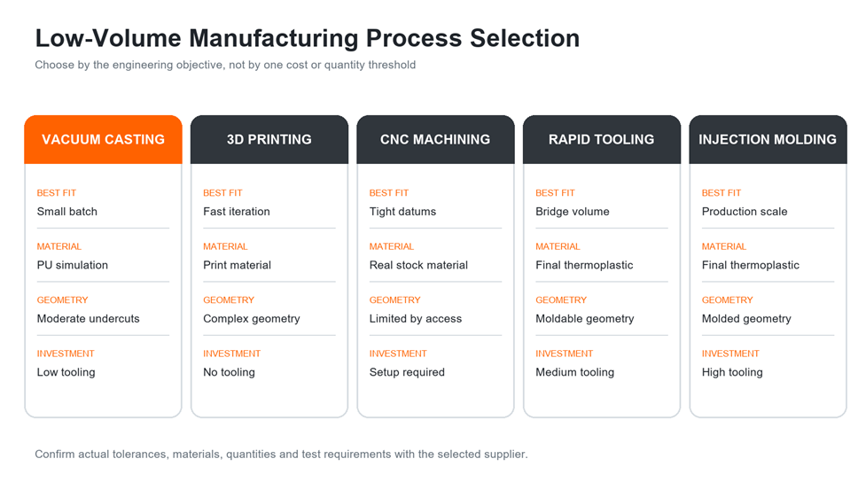
|
Process |
Strongest use case |
Material fidelity |
Tooling investment |
Repeatability at scale |
|
Vacuum casting |
Small batches with refined appearance and configurable polyurethane behavior |
Simulates selected plastics or elastomers |
Low |
Moderate and dependent on mold condition |
|
Direct 3D printing |
Fast design iterations and complex geometry |
Uses process-specific printing materials |
None |
Good for controlled print workflows, but surface and anisotropy vary |
|
CNC machining |
Precise prototypes in real engineering plastics or metals |
Uses actual stock material |
Low setup and fixturing |
High for machinable geometry |
|
Rapid tooling |
Bridge production in production-intent thermoplastic |
Uses injection-molding resin |
Medium |
Higher than silicone tooling |
|
Production injection molding |
Stable high-volume thermoplastic production |
Uses final specified resin |
High |
High after process validation |
Our rapid prototyping services combine these processes so each validation stage can use the appropriate material and manufacturing method.
Common Vacuum Casting Defects and Corrective Actions
|
Defect |
Likely causes |
Corrective direction |
|
Bubbles or voids |
Moisture, incomplete degassing, blocked vent or turbulent filling |
Control material storage, degas correctly, improve venting and fill from a stable location |
|
Incomplete fill |
Resin gels too early, thin section, long flow path or inadequate vent |
Review working time, material temperature, gate size, wall thickness and vent location |
|
Soft or sticky areas |
Incorrect mix ratio, poor mixing, contamination or incomplete cure |
Use controlled weighing and mixing; follow the resin cure schedule |
|
Distortion or warpage |
Early demolding, uneven section, unsupported geometry or post-cure movement |
Extend cure, improve support and review wall uniformity and fixture needs |
|
Excess flash |
Mold mismatch, poor closure, damaged split line or resin pressure |
Restore registration, improve closure and repair or replace the mold |
|
Surface pits or texture loss |
Defective master, contamination, mold damage or trapped air |
Refinish the master, clean the mold and improve local venting |
|
Color variation |
Inconsistent pigment ratio, incomplete mixing or cure variation |
Standardize weighing, masterbatch preparation and cure conditions |
|
Clear-part haze |
Master not polished, contaminated mold, moisture or unsuitable resin/cure |
Define a polishing standard and control resin, mold and post-cure conditions |
Quality Control for Vacuum-Cast Parts
A useful inspection plan focuses on the purpose of the prototypes. Typical controls include:
- verification of the master against CAD and critical dimensions;
- approval of split-line, gate and vent locations before mold production;
- first-article dimensional and cosmetic approval;
- color, gloss and texture comparison under controlled lighting;
- assembly checks with mating components;
- hardness testing for flexible parts;
- functional testing at relevant temperature and load;
- visual monitoring of mold wear across the batch;
- final quantity and traceability records.
Stratasys notes that flexible silicone tools can accommodate undercuts and that problematic features may be machined or drilled after casting when this improves reliability. See its silicone molding technical application guide.
What to Include in a Vacuum Casting RFQ
Send enough information for the supplier to plan the master, mold and inspection method:
- 3D CAD in STEP format;
- 2D drawing with functional dimensions and datums;
- required quantity, including any spare approval samples;
- target rigidity, flexibility, hardness or transparency;
- color reference, gloss and texture requirements;
- marked cosmetic surfaces and acceptable gate/vent locations;
- insert, thread or assembly requirements;
- operating temperature, chemical exposure and test conditions;
- mating components or assembly CAD;
- required inspection documents and delivery schedule.
Vacuum Casting DFM Checklist
Before releasing the order, confirm that:
- The design is stable enough to justify a silicone mold.
- The master-pattern finish matches the intended cast surface.
- Critical surfaces, datums and dimensions are identified.
- Wall thickness is practical for resin flow and demolding.
- Corners and boss roots use suitable radii.
- Split line, gate, vent and trimming locations are acceptable.
- Undercuts will not tear the part or shorten mold life excessively.
- Holes, inserts and threads have a documented manufacturing plan.
- The selected polyurethane properties match the actual test objective.
- Quantity planning accounts for mold wear and approval samples.
Request a Vacuum Casting DFM Review
Send your CAD files, quantity, material behavior, color, cosmetic requirements and test objectives. Samshion can review the master strategy, silicone mold layout, casting material and inspection plan before quotation.
Frequently Asked Questions
Is vacuum casting the same as urethane casting?
The terms are often used interchangeably for producing polyurethane parts in a silicone mold under controlled vacuum. Some suppliers use “urethane casting” more commonly in North America.
Does vacuum casting use the same plastic as injection molding?
Usually not. It uses two-component casting resins formulated to approximate selected properties of ABS, PP, rubber or other production materials. If testing requires the exact final thermoplastic, consider machining, direct printing in a qualified material or injection molding with rapid tooling.
Is vacuum casting suitable for end-use parts?
It can be suitable for controlled low-volume applications when the selected resin meets the service requirements. Long-term heat, UV, chemical exposure, creep, impact and regulatory requirements must be verified for the actual casting resin.
Can vacuum-cast parts include metal inserts?
Yes. Threaded inserts, pins and other hardware can be positioned in the mold when their location, sealing and retention are planned. Inserts can also be installed after casting when that provides better dimensional control.
Can vacuum casting make transparent parts?
Yes, but transparency depends on master polishing, silicone condition, mold cleanliness, resin selection, degassing, cure and post-processing. Define whether the requirement is general transparency, display quality or an optical function.
When should I switch from vacuum casting to injection molding?
Consider switching when quantities increase, the final thermoplastic is required, unit consistency becomes more important, or repeated silicone molds cost more than an appropriate bridge or production tool.