Let’s take a closer look at plastic shrinkage in injection molding and figure out how it occurs. All thermoplastics expand when melted at high temperatures and contract as they cool and solidify inside the mold. This dimensional reduction is called shrinkage, an unavoidable physical property of plastic materials. Uncontrolled shrinkage leads to sink marks, dimensional deviations, warpage and loose snap fit assembly.
What Is Injection Molding Shrinkage?
Plastic shrinkage refers to the volume and dimensional reduction of molded parts during the cooling and solidification stage. When plastic transitions from a high-temperature molten state to a solid state, polymer molecular chains tighten and contract, leading to size reduction.
Shrinkage rates vary drastically by material: semi-crystalline plastics feature high shrinkage, while amorphous plastics have low and stable shrinkage. Normal industrial shrinkage ranges from 0.1% to 3.0% based on resin types.
What Causes the Shrinkage of Injection Molding
Shrinkage issues are never caused by a single factor. They stem from three core dimensions: material properties, mold design defects, and improper injection process parameters.
Material Property Differences (Fundamental Cause)
Material molecular structure determines the inherent shrinkage rate of plastic parts. Semi-crystalline resins form tight, ordered molecular structures after cooling, resulting in large volume contraction. In contrast, amorphous resins maintain disordered molecular arrangements with minimal shrinkage.
High shrinkage materials (1.0%–3.0%):
PP, PE, PA6, PA66, POM
These materials are prone to severe sink marks, shrinkage dents, and long-term creep deformation.
Low shrinkage materials (0.3%–0.8%):
ABS, PC, PS, PMMA
These materials deliver stable dimensions and are widely used for precision structural parts.
Additionally, recycled materials with unstable molecular weight and uneven mixing will cause inconsistent shrinkage across production batches.
Unreasonable Mold Design (Structural Cause)
Poor mold design is the leading cause of local shrinkage and uneven shrinkage defects, even with standard process parameters.
Uneven wall thickness: Thick wall sections cool slower than thin areas, leading to concentrated shrinkage and obvious sink marks on part surfaces.
Improper gate and runner design: Undersized gates or misplaced runners freeze prematurely, cutting off the feeding channel before thick areas are fully compensated.
Poor cooling system layout: Unbalanced mold cooling causes inconsistent cooling speed, resulting in differential shrinkage and part warpage.
Insufficient mold shrinkage compensation: Failure to reserve standard shrinkage margins during mold cavity machining leads to undersized final parts.
Improper Injection Process Parameters (Controllable Cause)
Most on-site shrinkage problems come from unreasonable process settings, which can be quickly optimized for improvement.
Insufficient packing pressure & short packing time: The core cause of shrinkage. Not enough molten plastic is fed to compensate for volume contraction during cooling.
Excessively high melt temperature & mold temperature: Higher temperatures increase plastic fluidity but expand the molten volume, leading to larger shrinkage after cooling.
Unreasonable injection speed: Overly fast injection causes unstable filling and uneven internal density; overly slow speed leads to premature material cooling and insufficient feeding.
Short cooling time: Parts are ejected before full solidification, resulting in secondary shrinkage and dimensional deformation.
Practical Solutions to Eliminate & Reduce Shrinkage Defects
We summarize targeted solutions corresponding to the above three causes, covering material adjustment, mold optimization, and process tuning for full-scene improvement.
Material Optimization Solutions
Select Low-Shrinkage Base Resins
Prioritize amorphous plastics for precision parts with strict dimensional requirements, as they feature low and stable shrinkage rates:
- Recommended materials: ABS, PC, PC/ABS alloy, PS, PMMA
- Advantage: Shrinkage range only 0.3%~0.8%, rarely causes severe sink marks or dimensional deviation
- Avoid pure crystalline polymers (PP, POM, PA6, PE) for high-precision assemblies such as snap fits
Add Fillers & Reinforcements to Reduce Shrinkage
Fillers break up regular molecular crystallization and cut overall shrinkage effectively, the most widely used improvement method:
Glass Fiber (GF) Modified Materials
- 10%~30% glass fiber filled PP / PA6 / PA66 / POM
- Effect: Shrinkage reduced by 40%~70%, greatly improves dimensional stability and creep resistance
- Suitable for long-term locking snap structures to prevent looseness from shrinkage deformation
Mineral Filler (Talc, Calcium Carbonate)
- Talc-filled PP is the mainstream low-cost option for housings
- Balances shrinkage while reducing warpage caused by uneven fiber orientation
- Disadvantage: Slightly lowers material toughness and fatigue performance
Control Recycled Material Ratio
- Excess regrind leads to unstable molecular weight, inconsistent batch shrinkage and random sink marks
- Standard limit: Keep recycled material proportion below 20%
Mix virgin and recycled pellets evenly before feeding to avoid local shrinkage difference
Use Low-Crystallinity Modified Grades
Choose copolymerized crystalline plastics instead of homopolymer: e.g., PP copolymer vs homopolymer PP
Copolymer resins slow down crystallization speed, lower total shrinkage and reduce sink mark tendency on thick bosses/ribs
Add Shrinkage-Reducing Additives
- Crystallization retardants: Slow molecular crystallization to cut volume contraction.
- Internal lubricants: Improve melt filling, ensure full packing compensation for thick-wall areas.
- Anti-creep additives: Minimize long-term secondary shrinkage of PP/ABS snap fits.
Material Matching for Over molded Parts
For dual material overmolding products:
- Match shrinkage rates of hard substrate and soft TPU as closely as possible
- Large shrinkage mismatch will trigger differential shrinkage, surface indentation and part delamination.
Mold Design Optimization Solutions
Optimize part wall thickness: Keep wall thickness uniform; avoid thick bosses and rib structures. For unavoidable thick areas, set hollow structures to reduce shrinkage space.
Upgrade gating system: Enlarge gate size, adjust gate position to face thick-wall areas, and extend runner freezing time for sufficient feeding compensation.
Balance cooling system: Optimize cooling water channel layout to ensure synchronous cooling of thick and thin areas, eliminating differential shrinkage.
Reserve accurate shrinkage tolerance: Set mold cavity compensation values according to material shrinkage rate to offset cooling shrinkage.
Injection Process Parameter Tuning (Fast On-Site Fix)
These adjustments can solve 80% of temporary shrinkage issues in mass production:
Increase packing pressure and extend packing time: The most effective solution. Ensure continuous molten plastic filling to compensate for cooling volume loss.
Properly lower melt and mold temperature: Reduce molten plastic expansion volume and shrinkage amplitude after solidification.
Optimize injection speed: Adopt slow-fast-stable segmented injection to ensure uniform cavity filling and consistent internal density.
Extend cooling time: Ensure parts are fully solidified in the mold before ejection to avoid secondary deformation.
What’s the difference of Shrinkage vs. Warpage
Many engineers confuse shrinkage and warpage:
Shrinkage: Uniform or local volume reduction, causing small size errors and surface sink marks. There are two types of shrinkage.
Bulk shrinkage: The whole part gets smaller evenly. Mold makers add shrinkage compensation to cavity size to fix overall dimensional deviation.
Local shrinkage (sink marks): Thick sections (bosses, ribs) cool slower, surface dents inward due to insufficient packing feed.
Warpage: uneven shrinkage in different part areas, resulting in bending, twisting, and shape deformation. The overall size may still be within tolerance, but the geometry is distorted. Flat surfaces become bowed; rectangular parts twist.
Controlling uniform shrinkage is the fundamental way to eliminate warpage defects.
Shrinkage vs. Warpage Comparison Table
| Item | Shrinkage | Warpage |
| Core performance | Part becomes smaller in size | Part bends, twists or bows |
| Root mechanism | Volume contraction of plastic after cooling | Uneven shrinkage creates residual stress |
| Typical defects | Small dimension size, sink marks on thick areas | Curved surfaces, twisted frames, uneven flatness |
| Quick process fix | Increase packing pressure & packing time | Balance cooling, adjust injection speed, reduce uneven packing |
| Permanent solution | Add mold shrinkage compensation, unify wall thickness | Optimize cooling layout, symmetric part design, add stiffening ribs |
FAQ About Injection Molding Shrinkage
Q1: Is plastic shrinkage completely avoidable?
A1: No. All thermoplastics shrink after cooling. The goal of production control is to stabilize shrinkage within tolerance range rather than eliminate it completely.
Q2: Why do only thick areas have sink marks?
A2: Thick walls store more heat and cool slower than surface thin areas. After the surface solidifies, the internal material continues to shrink, causing surface denting and sink marks due to no feeding compensation.
Q3: Can process adjustment replace mold modification for shrinkage issues?
A3: Temporary shrinkage problems can be fixed by parameter tuning. However, severe structural shrinkage caused by uneven wall thickness or unreasonable gate design must rely on mold optimization for fundamental resolution.
Q4: How to improve shrinkage of PP and PA parts?
A4: Add glass fiber fillers, increase packing pressure, optimize wall thickness uniformity, and avoid independent thick boss structures.
Q5: What are the main negative impacts of excessive shrinkage?
A5:
- Appearance defects: Obvious sink marks and surface depressions;
- Dimensional failure: Overall part size out of tolerance, causing loose assembly;
- Warpage & distortion: Differential shrinkage between thick and thin areas bends or twists the finished part.
Q6: Can shrinkage be completely avoided during production?
A6: No. All thermoplastics will shrink after cooling. The target of manufacturing control is to stabilize shrinkage within the drawing tolerance range, rather than eliminate shrinkage entirely. Reasonable material selection, mold design and process control can minimize shrinkage-related defects.
Injection molding shrinkage is a systematic defect affected by materials, molds, and processing technologies.
For manufacturers, the best shrinkage control strategy is material selection first, mold optimization as the foundation, and process tuning as the fine adjustment. By standardizing each link, you can effectively avoid sink marks, dimensional errors, and warpage, and achieve stable high-precision injection molding production.
Injection molding shrinkage is the dimensional change that occurs as a polymer cools, solidifies and continues to reach equilibrium after molding. It is unavoidable, but it is not a single fixed percentage that can be copied from a generic material chart and applied to every feature of a part.
The actual result depends on the exact resin grade, filler content, moisture condition, part geometry, wall thickness, gate location, cavity-pressure history, cooling balance, fiber or molecular orientation and the time and environment in which the part is measured. A mold can therefore be built with a reasonable initial shrinkage allowance and still require sampling, measurement and controlled steel adjustment before critical dimensions are released.
This guide explains how molding shrinkage is defined and measured, why sink marks and warpage are related but different, how design and processing influence dimensional change, and how SAMSHION approaches shrinkage control in custom injection molding programs.
Key Takeaways
- Every thermoplastic shrinks, but the amount and direction are specific to the resin grade, geometry and molding conditions.
- A supplier datasheet value is a starting point for tool design, not a guaranteed result for every dimension on a real component.
- Packing can compensate for volumetric contraction only while pressure can still reach the region through an unfrozen flow path.
- Uniform shrinkage changes size; non-uniform shrinkage can create sink marks, voids, residual stress and warpage.
- Fiber-filled materials can shrink differently parallel and transverse to flow, so one isotropic scale factor may be inadequate.
- Critical dimensions require an agreed conditioning time, measurement temperature, datum system and acceptance method.
- Process changes should be made within the material supplier’s recommended window and validated against all quality requirements, not only one dimension.
What Is Injection Molding Shrinkage?
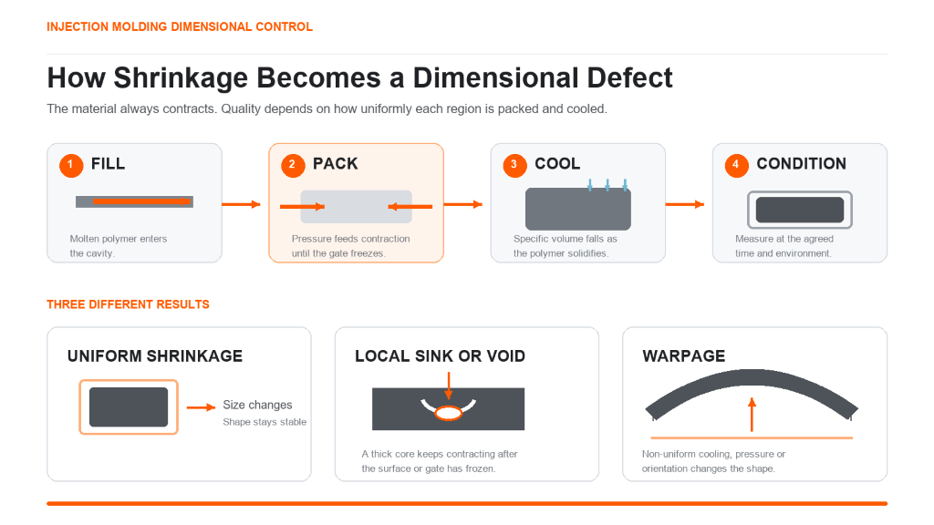
During filling, the polymer is hot and pressurized. As it cools, its specific volume decreases. While the gate remains open, packing pressure can feed additional material into the cavity and compensate for part of that contraction. After the gate freezes, no more material can enter through that gate. The polymer continues to cool and the molded part eventually separates from the cavity or core surfaces, is ejected and continues changing dimension outside the mold.
For engineering work, it is useful to distinguish three related terms.
Molding Shrinkage
Molding shrinkage compares the relevant mold dimension with the corresponding molded-part dimension after a defined initial conditioning period. The result is normally expressed as a percentage or as a length change per unit length.
Post-Molding Shrinkage
Post-molding shrinkage is the additional dimensional change that occurs after the initial measurement. It may result from continued crystallization, stress relaxation, thermal exposure or environmental conditioning. Moisture uptake can also change dimensions, particularly for hygroscopic materials, although moisture expansion should be identified separately when evaluating the final conditioned size.
Total Dimensional Change
The customer usually cares about the dimension at assembly, validation or use. That final result may include molding shrinkage, post-molding change, moisture conditioning, temperature effects and mechanical constraint in the assembly. The measurement plan must therefore state when and under what conditions the part is accepted.
The official ISO 294-4 method for molding shrinkage distinguishes molding and post-molding shrinkage and measures behavior parallel and normal to melt flow on standardized thermoplastic test specimens. Real components are more complex than test plaques, but the standard illustrates why direction and conditioning cannot be ignored.
How Is Injection Molding Shrinkage Calculated?
A basic linear shrinkage calculation is:
Shrinkage (%) = (mold dimension – molded-part dimension) / mold dimension x 100
For example, if a defined mold dimension is 100.00 mm and the corresponding conditioned part dimension is 98.80 mm, the calculated shrinkage is 1.20%. This arithmetic is simple; selecting the correct dimensions and measurement conditions is not.
The following details must be controlled:
- Whether the mold dimension is measured at room temperature or corrected for tool temperature.
- Whether the part dimension is measured immediately after molding, after 24 or 48 hours, after moisture conditioning, or after a specified thermal exposure.
- Whether the dimension is parallel, transverse or through-thickness relative to flow and reinforcement orientation.
- Whether the part is measured free-state, restrained in a fixture or assembled into another component.
- Which datum features and inspection method are used.
- Whether the result comes from one cavity, several cavities or a statistically representative production run.
Why Datasheet Shrinkage Is Only a Starting Point
Material datasheets usually report shrinkage from a standard specimen under defined test conditions. A production component may have different flow length, wall thickness, gate size, pressure distribution, cooling and fiber orientation. Even parts molded from the same grade can show different dimensions when the gate, tool temperature or packing history changes.
Celanese’s official Celcon POM processing guide explains that shrinkage is influenced by resin properties, filler, wall thickness, gate size, flow direction and molding conditions, and that exact shrinkage for a specific part is difficult to predict. The guide recommends using published values as an initial estimate and leaving appropriate adjustment strategy in the tool.
Flow-Direction and Transverse Shrinkage
An unfilled material may still exhibit orientation effects, while short fibers and other reinforcements can make the difference more pronounced. Fibers tend to align with melt flow and restrain shrinkage more strongly along their orientation than across it. A technical datasheet for one glass-filled grade may therefore publish separate parallel and normal values.
This anisotropy can turn a nominally flat or circular feature into a warped or oval result. Gate position, weld lines and local changes in flow direction alter the orientation field, so the shrinkage allowance may need feature-specific review rather than one scale factor applied to the entire CAD model.
What Causes Injection Molding Shrinkage?
Shrinkage is created by material thermodynamics and modified by the pressure, temperature and constraint history of each region of the part. A useful diagnosis separates the material, part, mold and process contributions instead of blaming one setting.
1. Polymer Structure and Crystallization
Amorphous polymers solidify without forming a large ordered crystalline fraction. Semi-crystalline polymers develop crystalline regions as they cool, which usually produces a larger and more condition-sensitive volume change. This general distinction is useful, but resin family alone is not enough for tool design.
Two grades with the same base polymer can behave differently because of molecular weight, copolymer composition, fillers, impact modifiers, flame retardants, colorants or supplier formulation. Always use data for the exact commercial grade and intended condition.
2. Filler Type, Content and Orientation
Glass fibers, mineral fillers and other reinforcements often reduce shrinkage in one or more directions, but they also introduce directional behavior. More reinforcement does not automatically mean a flatter part. The orientation pattern may increase the difference between the flow and transverse directions and create bending or twisting when the geometry or gate layout is unbalanced.
Changing from an unfilled to a glass-filled resin is therefore a material and structural decision, not a universal shrinkage remedy. It can affect impact performance, surface appearance, weld-line strength, wear on the mold, dimensional behavior and regulatory documentation.
3. Packing Pressure and Packing Time
Packing adds material after volumetric filling and compensates for contraction while the flow path remains open. Higher effective cavity pressure at solidification generally reduces local volumetric shrinkage, but the machine setting is not the same as pressure everywhere in the cavity.
Pressure falls along the flow path. Areas near the gate can be packed more strongly than regions near the end of fill. If the gate or a thin connecting section freezes before a thick region is sufficiently packed, increasing the programmed hold time alone may no longer change that region.
Autodesk’s official explanation of packing profiles and shrinkage distribution describes how non-uniform cavity pressure can create different shrinkage near the gate and end of fill. The practical objective is not simply maximum pressure; it is a stable and appropriate pressure history across the part without flash, over-packing, excessive residual stress or tool damage.
4. Gate Size, Gate Location and Gate Freeze
The gate is the pressure-transmission path during packing. A small gate may freeze early. A gate placed through a thin section may cut off feeding to a thicker downstream region. A large gate may improve packing but leave a larger vestige, extend cycle time or increase local orientation and stress.
Gate decisions should consider:
- Which regions are thick and need the longest feeding time.
- Cosmetic restrictions and vestige limits.
- Weld-line location and venting.
- Flow length and pressure loss.
- Fiber orientation and expected warpage.
- Whether the runner and gate can be removed automatically.
5. Wall Thickness and Local Mass
Thick areas cool and solidify more slowly than thin walls. The surface can freeze while the hotter core continues to contract. If the core cannot be replenished through an open flow path, the outside surface may pull inward and form a sink mark, or an internal void may form instead.
Common high-risk features include thick bosses, ribs that are too thick relative to the nominal wall, intersections of multiple ribs, abrupt wall transitions and heavy mounting pads. Coring out thick regions and using gradual transitions usually provides a more robust solution than trying to hide every defect with process settings.
6. Mold and Melt Temperature
Temperature effects are material- and geometry-dependent. Changing mold temperature affects frozen-layer formation, crystallization, pressure transmission, surface replication, residual stress and cooling balance. Changing melt temperature affects viscosity, fill pressure, orientation and the amount of heat that must be removed.
This is why the instruction “lower the mold and melt temperature to reduce shrinkage” is unsafe as a general rule. A colder mold can harm surface finish or increase post-molding change in some semi-crystalline materials. BASF’s technical guide to estimating injection-molding cooling time notes that cavity-wall temperature must remain suitable for quality and that an excessively cold mold can create poor surface or post-molding shrinkage in semi-crystalline polymers.
7. Cooling Balance
Different mold-surface temperatures cause different solidification histories. A hot core and cold cavity, a poorly cooled slide, a deep boss or a hot-runner nozzle area can create asymmetric shrinkage through the wall or across the part.
Cooling analysis should review channel distance, channel diameter, circuit flow, temperature rise, insert conductivity, contact resistance and local heat concentration. Process troubleshooting should confirm actual inlet and outlet temperatures and flow, not only the setpoint on the temperature-control unit.
8. Ejection and Residual Stress
A part that is ejected while too hot or too soft can deform under ejector load, core friction or its own weight. Residual stress can relax after ejection and change the measured shape. Increasing cooling time may help when the problem is insufficient rigidity at ejection, but it does not correct an unbalanced cooling layout or inappropriate draft.
9. Moisture and Environmental Conditioning
Hygroscopic polymers can change dimension as they absorb moisture. This is not the same mechanism as initial cooling shrinkage, but it affects final assembly dimensions. Dry-as-molded inspection and conditioned inspection can produce different results.
The drawing and control plan should state the conditioning requirement for critical dimensions. Material drying before molding must also follow the supplier’s recommendations because moisture can affect viscosity, hydrolysis, appearance and mechanical properties.
Amorphous, Semi-Crystalline and Filled Materials
Material-family comparisons are useful for early planning but should never replace grade-specific data.
Amorphous Thermoplastics
Examples include ABS, PC, PMMA and many PS grades. These materials often show lower and more uniform mold shrinkage than unfilled semi-crystalline polymers, but part dimensions can still change with packing, orientation, stress and temperature. Optical, cosmetic or stress-cracking requirements may be more important than the nominal shrinkage percentage.
Semi-Crystalline Thermoplastics
Examples include PP, PE, POM, PA, PBT and PPS. Their crystallization behavior can increase shrinkage and process sensitivity. This does not make them unsuitable for precision parts. Many high-performance gears, clips, connectors and structural components use these materials successfully when grade selection, tool compensation, conditioning and process control are planned correctly.
Reinforced and Mineral-Filled Grades
Reinforcement often improves stiffness and reduces shrinkage magnitude, but it can increase anisotropy. The finished part can be dimensionally stable in one direction and less stable in another. Moldflow simulation, controlled gate design and physical sampling are especially valuable for large flat parts, asymmetric housings and tolerance-critical assemblies.
Regrind and Recycled Content
There is no universal rule that every process must keep regrind below 20%. The permitted level depends on the resin, degradation risk, contamination control, cosmetic requirements, mechanical performance, color, regulatory obligations and customer specification.
If regrind or recycled content is allowed, define the source, maximum number of heat histories, blending method, drying, filtration, traceability and verification plan. Changes in viscosity or composition can change filling and pressure distribution even when the nominal base polymer remains the same.
Shrinkage, Sink Marks, Voids and Warpage: What Is the Difference?
These terms are related but should not be used interchangeably.
Uniform Shrinkage
Uniform shrinkage is primarily a size change. A rectangular part remains rectangular but becomes smaller. Tool dimensions can compensate for a stable and repeatable amount of uniform shrinkage.
Sink Marks
Sink marks are localized surface depressions. They commonly appear opposite thick ribs, bosses or intersections when the interior continues contracting after the surface has frozen and the region is not adequately packed.
Internal Voids
A void can form when the outer surface is sufficiently rigid to resist pulling inward while the interior contracts. The absence of a visible sink mark does not prove that a thick section is internally sound. Sectioning, computed tomography or other appropriate inspection may be required for critical components.
Warpage
Warpage is a change in shape caused by variations in shrinkage or residual stress. It can arise from region-to-region differences, through-thickness temperature differences and orientation effects. A part may meet several local size dimensions and still fail flatness, profile or assembly.
Autodesk’s shrinkage versus warpage explanation summarizes the distinction clearly: shrinkage changes size, while warpage changes shape; real molded parts often contain both.
Design Guidelines to Control Shrinkage
Keep Nominal Walls as Uniform as Function Allows
Uniform wall thickness supports more predictable filling, packing and cooling. When thickness must change, use a gradual transition. Avoid large local masses at corners or feature intersections.
Core Out Thick Features
Replace solid pads and thick bosses with cored geometry where strength and molding access permit. A boss should be designed as part of the surrounding rib and wall system rather than as an isolated cylinder of material.
Size Ribs and Bosses for the Material and Appearance Requirement
There is no one rib-to-wall ratio that works for every resin, finish and loading case. Start with supplier and molder guidance, then evaluate sink risk, stiffness, ejection and tooling access. Highly visible Class-A surfaces require more conservative geometry than hidden structural surfaces.
Provide Draft and Stable Ejection
Adequate draft reduces core friction and ejection stress. Textured surfaces generally need more draft than polished surfaces. Ejector locations should support the part without creating local distortion or witness marks outside the approved cosmetic zones.
Gate with Packing and Orientation in Mind
Where feasible, gate into a region that can maintain a molten path to thick sections during packing. Consider how the flow direction will orient fibers and how multiple flow fronts will meet. Gate location is a dimensional-control decision, not only a filling decision.
Design Cooling Around Heat Load
Cooling channels should address deep cores, thick pads, slides and hot spots, not simply follow a uniform pattern in the mold base. High-conductivity inserts, baffles, bubblers or conformal cooling may be justified when conventional drilling cannot reach the region effectively.
Define Functional Datums and Tolerances
Do not apply an unnecessarily tight blanket tolerance to every dimension. Identify assembly, sealing, optical and motion-critical features. Use a functional datum reference frame and geometric controls where they communicate the requirement more clearly.
For broader material selection, review SAMSHION’s manufacturing materials guide. For appearance-sensitive components, coordinate dimensional decisions with the selected injection mold surface finish.
Tooling Strategy for Dimensional Control
Begin with Grade-Specific Data
Request the current technical datasheet and processing guide for the exact resin grade, including filler and color where relevant. Record the data source and test method used for the initial allowance.
Leave a Controlled Adjustment Direction
When practical, design critical tooling dimensions so material can be removed from steel after the first trial rather than requiring weld repair. Mold builders often describe this as leaving the tool “steel safe.” The correct adjustment direction depends on whether the feature is formed by a cavity, core, insert, slide or shut-off.
Use Replaceable Inserts for High-Risk Features
Critical snap dimensions, sealing details, holes, bosses and locally uncertain geometry may be placed on replaceable inserts. This reduces the cost and risk of adjustment after measurement.
Sample at Stable Conditions
Do not approve dimensions from a few unstable start-up shots. Establish repeatable melt preparation, temperatures, fill, transfer, cushion, packing, cooling and cycle time. Record the actual conditions used for the samples.
Measure Before Final Steel Adjustment
Measure the correct cavities, features and conditioning state. Compare the result with the functional tolerance and expected process variation. A single part does not establish a reliable offset.
SAMSHION’s article on rapid tooling versus production tooling explains how insert strategy, validation and expected demand affect the appropriate mold construction.
Process Control: How to Reduce Variation
The goal is a repeatable process that produces acceptable dimensions and appearance, not the lowest possible shrinkage number.
1. Prepare the Material Correctly
Dry hygroscopic resins according to the supplier’s temperature, time, airflow and dew-point recommendations. Prevent contamination and excessive residence time. Control permitted regrind and lot blending.
2. Stabilize Filling and Transfer
Monitor shot size, cushion, screw recovery, injection time and transfer position. Velocity-to-pressure transfer should occur consistently. Machine or check-ring instability can appear as dimensional variation even when the programmed settings do not change.
3. Establish Effective Packing
Use a gate-seal study, part weight, dimensions and process data to determine whether additional hold time still changes the result. Adjust pressure and time within the safe mold and machine limits. Watch for flash, over-packing, high ejection force and residual stress.
4. Maintain the Approved Temperature Window
Control actual melt temperature and mold-surface temperature rather than relying only on machine setpoints. A temperature change can improve one symptom while worsening surface finish, crystallinity, weld-line strength or cycle stability.
5. Cool Until the Part Can Be Ejected Reliably
Cooling time should provide sufficient rigidity for ejection and handling. Confirm that the cooling circuits deliver the intended temperature and flow. If one region remains hot, extending the overall cycle may mask rather than solve the mold-design problem.
6. Lock the Validated Process Window
Record the acceptable ranges for material, temperatures, injection velocity, transfer, pressure, hold time, cooling and cycle. Monitor the variables that correlate with critical dimensions. First-piece approval alone is not a substitute for ongoing process control.
A Practical Shrinkage Troubleshooting Workflow
Step 1: Classify the Defect
Determine whether the problem is global undersize, local sink, internal void, ovality, bow, twist, flatness, feature position or post-conditioning movement. Photograph and map the affected region.
Step 2: Confirm the Measurement System
Verify datums, fixture, instrument, program, part temperature and conditioning time. Repeat measurements across operators or equipment if the result is close to the tolerance limit.
Step 3: Check Material and Machine Stability
Confirm resin grade, lot, drying, moisture, colorant, regrind, melt preparation, cushion, transfer and cycle consistency. Separate a material or equipment variation from a persistent geometric problem.
Step 4: Run a Gate-Seal and Packing Study
Increase hold time in controlled steps while tracking part weight and critical dimensions. Once additional time no longer changes the result, the gate is probably sealed under those conditions. Then evaluate the pressure level and distribution.
Step 5: Review Cooling and Ejection
Measure mold-surface temperatures, coolant flow and temperature rise. Check whether the part is soft or distorted at ejection and whether one side or local insert runs hotter.
Step 6: Review Geometry and Gate Access
Look for thick intersections, early-freezing thin connections, poor gate placement and orientation-driven asymmetry. If pressure or cooling cannot physically reach the region, continued parameter changes are unlikely to provide a robust solution.
Step 7: Decide Between Process, Tool and Part Changes
A process correction is appropriate when the mold and geometry can produce the requirement within a stable window. A tool correction is appropriate when cavity compensation, gate, cooling or insert geometry must change. A part-design change is appropriate when local mass, stiffness or tolerance structure makes the requirement physically or economically unstable.
Quick Diagnostic Matrix
|
Symptom |
Verify first |
Common contributing mechanisms |
Typical engineering response |
|
Part is uniformly undersize |
Conditioning time, resin grade, cavity dimension and stable process |
Initial allowance too low; higher-than-assumed shrinkage; insufficient effective packing |
Confirm data, establish process, then adjust tool steel in the planned direction |
|
Sink opposite a rib or boss |
Wall-to-feature relationship, gate freeze, part weight and cavity pressure |
Local mass; frozen feed path; inadequate packing; hot spot |
Core out or resize feature, improve feeding/cooling, then optimize packing |
|
Internal void in a thick section |
Sectioning or suitable non-destructive inspection |
Core contraction after surface freeze |
Reduce local mass, improve gate access and packing, review material/process |
|
Flat panel bows |
Temperature map, gate/orientation pattern and support at ejection |
Differential cooling; differential shrinkage; fiber orientation; residual stress |
Balance cooling and flow, review stiffness and gate location, validate ejection |
|
Dimension changes after 24-48 hours |
Measurement timing, storage temperature and humidity |
Post-crystallization, stress relaxation or moisture conditioning |
Define conditioning state, adjust process/tool for the accepted condition |
|
Cavities do not match |
Cavity pressure, cooling, venting and tool dimensions by cavity |
Runner imbalance, cooling variation, steel variation or vent condition |
Correct balance and cavity-specific causes before applying one global offset |
Dimensional Validation and Quality Control
An effective dimensional plan should be agreed before final tool approval.
Define the Acceptance Condition
State the time after molding, temperature, humidity and any preconditioning or annealing. For hygroscopic polymers, specify whether dimensions are accepted dry-as-molded or moisture-conditioned.
Identify Critical-to-Quality Features
Separate safety, assembly, sealing, appearance and process-critical characteristics from general reference dimensions. Define measurement frequency and reaction plans accordingly.
Use the Correct Inspection Method
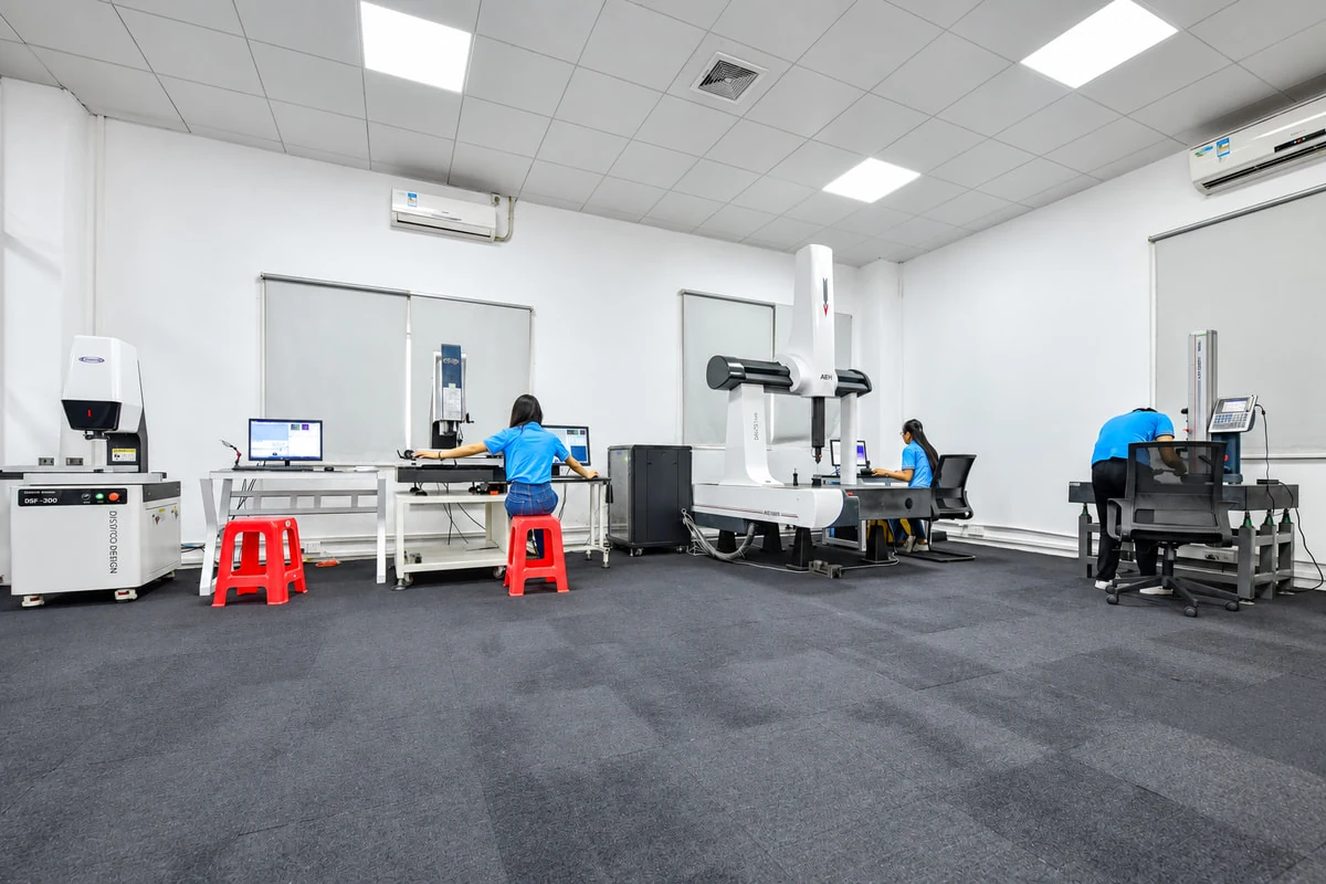
Calipers may be suitable for simple non-critical dimensions but can distort flexible parts. CMM, optical measurement, gauges, scanning or fixtures may be needed for profile, free-state warpage or complex datum relationships.
Compare Cavities and Time Points
Multi-cavity tools should be evaluated cavity by cavity. Measure initial samples and, when relevant, later conditioned samples. Track both the average and variation.
Control Changes
Resin-grade changes, colorants, filler changes, alternate suppliers, recycled content and large process-window changes can alter dimensional behavior. Use documented change control and revalidation appropriate to the part risk.
SAMSHION’s quality assurance and inspection systems support first-article inspection, dimensional reporting and production verification for molded components.
When Should You Use Moldflow Simulation?
Simulation can help compare gate locations, pressure distribution, cooling, fiber orientation, volumetric shrinkage and predicted warpage before steel is cut. It is especially valuable for large flat parts, glass-filled materials, multi-gate designs and tolerance-critical assemblies.
Simulation is not a dimensional guarantee. Results depend on the mesh, process assumptions, material characterization, cooling model, boundary conditions and actual tool construction. Autodesk notes that measured shrinkage data can substantially improve prediction compared with a model that lacks characterization. Use simulation to compare risks and guide decisions, then validate with molded parts.
Shrinkage in Overmolded and Multi-Material Parts
Overmolded parts combine materials, thermal histories and mechanical constraints. The substrate may restrain the overmold, while the overmold may pull on a thin substrate during cooling. Shrinkage mismatch can contribute to curl, local read-through, edge lift or interfacial stress.
Material compatibility remains essential, but matching two nominal datasheet percentages does not guarantee a flat assembly. Review substrate stiffness, insert temperature, overmold thickness, gate direction, adhesion, mechanical interlock and conditioning. See the overmolding design guide for a broader DFM and production framework.
Information to Provide for a Shrinkage Review
Send the following information with your RFQ or DFM request:
- Native 3D CAD model and a controlled 2D drawing.
- Exact resin manufacturer, grade, filler, color and regulatory requirements.
- Expected annual and lifetime quantity.
- Critical dimensions, datums, flatness, profile and assembly conditions.
- Cosmetic surfaces, texture and approved sample requirements.
- Conditioning and inspection requirements.
- Mating-part CAD and assembly constraints where relevant.
- Historical measurements or defects from an existing tool.
- Required documentation, capability or validation package.
From CAD to Dimensionally Stable Molded Parts
1. Review the Part and Material
SAMSHION reviews wall thickness, ribs, bosses, draft, gate options, surface requirements, resin data and critical dimensions.
2. Define the Tooling and Adjustment Strategy
The mold concept identifies cavities, inserts, gate, cooling, ejection and steel-safe features where adjustment may be required.
3. Manufacture and Sample the Tool
The tool is built, sampled under recorded conditions and reviewed for fill, appearance, dimensions, ejection and process stability.
4. Measure at the Agreed Condition
Parts are inspected using the defined datums, equipment and conditioning time. Results are separated by cavity when applicable.
5. Correct and Validate
Process, tool or part changes are selected according to the diagnosed cause. The agreed validation package is completed before production release.
Upload your CAD files and include the exact resin grade, critical dimensions and expected quantity. SAMSHION can review the likely shrinkage risks and propose an injection-molding and tooling strategy for your project.
Frequently Asked Questions
Can Injection Molding Shrinkage Be Eliminated?
No. Thermoplastics change volume as they cool and reach equilibrium. The engineering objective is to predict, compensate and control shrinkage so that the conditioned part meets its functional requirements.
What Is a Typical Plastic Shrinkage Rate?
There is no single reliable rate for “plastic.” Published values vary by resin family, exact grade, reinforcement, test direction and method. Use the exact supplier datasheet as an initial reference and confirm the real component through sampling.
Is a Semi-Crystalline Plastic Unsuitable for Precision Parts?
No. Semi-crystalline materials can be used successfully for precision components when the grade, geometry, conditioning, tool allowance and process are designed for their behavior. Avoiding an entire material family solely because of shrinkage can sacrifice wear, chemical resistance or mechanical performance.
Does More Packing Pressure Always Reduce Shrinkage?
Effective cavity pressure can reduce local volumetric shrinkage while the flow path is open, but excessive pressure can cause flash, over-packing, residual stress, difficult ejection or tool damage. Pressure also drops along the flow path. Use a validated process rather than maximizing one setting.
Why Does Hold Time Stop Affecting Part Weight?
Once the gate freezes, additional programmed hold time cannot transmit more material through that gate. A gate-seal study uses part weight and dimensions to identify this point under controlled conditions.
Why Does a Part Change Size the Day After Molding?
Post-molding crystallization, stress relaxation, temperature change or moisture conditioning may continue after ejection. Define the acceptance time and environment so supplier and customer measure the same condition.
What Is the Difference Between Shrinkage and Warpage?
Shrinkage is primarily a change in size. Warpage is a change in shape caused by non-uniform shrinkage or residual stress. A real molded part may show both.
Can Glass Fiber Solve a Shrinkage Problem?
Glass fiber often reduces shrinkage along the fiber direction and increases stiffness, but it can create directional differences and affect impact, surface and weld-line performance. Material changes require full design and validation review.
When Is a Tool Modification Necessary?
Modify the tool when a stable process cannot meet the requirement because the cavity allowance, gate, cooling or insert geometry is wrong. Do not cut steel until the material, process, measurement system and conditioning state are confirmed.
Request an Injection Molding DFM Review
Dimensional control begins before mold steel is cut. Send SAMSHION your CAD model, drawing, exact resin grade, quantity, cosmetic requirements and critical dimensions. Our engineering team can review wall thickness, gate and cooling risks, tooling adjustment strategy, sampling and inspection requirements before production.