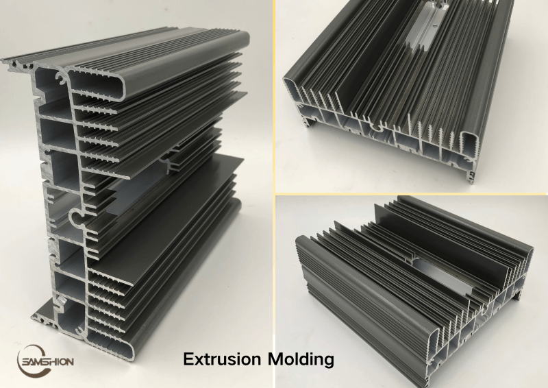
Extrusion molding is one of the most cost-effective, high-volume manufacturing processes for producing continuous cross-sectional profiles from plastics, aluminum, rubber, and composite materials. Widely used in construction profiles, automotive trim, industrial tubing, and consumer accessories, the quality, dimensional stability, and yield of extruded parts depend heavily on rational structural design and standardized process control. Poor part geometry or improper process settings often lead to persistent defects, increased scrap rates, and shortened die service life.
Structural Design Tips for Extrusion Molding Parts
Unlike injection molding, extrusion molding relies on continuous melt flow through a fixed die opening. All structural designs must comply with fluid flow rules, uniform cooling principles, and die processing limitations. Below are the mandatory structural requirements for qualified extruded parts.
Uniform Wall Thickness with Gradual Transition is The Top Priority of Extrusion Part Design
Uniform wall thickness is the top priority of extrusion part design. Consistent section thickness ensures balanced molten material flow velocity and uniform post-extrusion cooling, which is the foundation of dimensional stability and flatness. Abrupt thickness differences will cause inconsistent flow resistance, leading to uneven extrusion speed and asymmetric cooling shrinkage.
If functional requirements necessitate wall thickness changes, slow and smooth transitional sections are mandatory instead of step-like abrupt changes. The transition slope should be controlled within a reasonable range to avoid flow stagnation and residual stress concentration. For most plastic and aluminum extrusion profiles, the recommended wall thickness variation is controlled within ±0.15mm for precision parts and ±0.3mm for general industrial parts.
No Sharp Corners, Only Filleted Corners
Sharp internal and external corners are strictly prohibited in extrusion part structure design. Sharp corners create tiny flow dead zones during extrusion, where molten material accumulates, decomposes, or adheres to the die, resulting in surface streaks, material scorching, and frequent die cleaning downtime. Meanwhile, sharp corners form severe stress concentration points, making parts prone to cracking under external force or temperature cycling.
For metal extrusion (aluminum, steel), the minimum corner radius is 0.75mm; for plastic and rubber extrusion, a minimum radius of 0.5mm is required. Larger fillet radius further optimizes material flow, reduce die wear, and improve the overall structural strength of profiles.
What is The Reasonable Cavity and Undercut Structures of Extrusion Molding
Extrusion profiles can support multi-cavity and simple undercut structures to meet functional assembly needs, but overly complex internal cavities, deep narrow undercuts, or closed irregular grooves are unfeasible. These structures increase die processing difficulty, cause uneven melt distribution, and lead to local insufficient filling or residual material buildup.
Designers should ensure all cavity structures have smooth flow channels and avoid isolated narrow gaps. The width of internal grooves and cavities must match the extrusion ratio (the ratio of initial billet cross-sectional area to final product area) to prevent excessive die pressure and profile deformation.
How to Controll Aspect Ratio and Thin-Wall Limitation
Ultra-thin wall structures and excessive length-to-width aspect ratios are major design pitfalls for extrusion parts. Excessively thin walls lead to insufficient melt filling, easy warping and torsion during cooling, and poor structural rigidity. Overly large aspect ratios cause unbalanced radial force during extrusion, resulting in profile bending and dimensional deviation.
For conventional plastic extrusion, the minimum feasible wall thickness is 0.8–1.0mm; for precision micro-extrusion, the wall thickness should not be less than 0.5mm. Meanwhile, the circumscribed circle diameter of the profile must match the maximum pressure range of the extrusion equipment to avoid equipment overload and unstable molding.
Why Symmetrical and Balanced Cross-Section is So Important for Extrusion Molding
A symmetrical cross-section structure is highly recommended for extrusion parts. Symmetrical design balances material flow resistance in all directions, ensures consistent cooling shrinkage on both sides of the profile, and effectively avoids torsion, bending, and unilateral warping. For asymmetric profiles, designers must compensate for flow balance through structural optimization or die land length adjustment to offset natural flow deviation.
How to Avoid Problems and Defects in Extrusion Molding
Even with standardized structural design, extrusion molding is prone to various defects due to fluctuating process parameters, material quality issues, die wear, and equipment deviation. The following are the most frequent extrusion problems, with detailed causes and targeted solutions.
Avoid Uneven Wall Thickness & Dimensional Deviation
Symptoms: Local thick or thin sections of the profile, inconsistent outer diameter and inner hole size, out-of-tolerance overall dimensions.
Root Causes: Unreasonable part structural design with abrupt thickness transitions; die misalignment or uneven die gap; inconsistent melt temperature and screw speed; unbalanced material viscosity; worn die local areas leading to uneven flow.
Solutions: Optimize part structure to adopt uniform thickness and gradual transitions; calibrate die installation alignment regularly; stabilize extrusion temperature and speed parameters; filter and homogenize raw materials to ensure consistent viscosity; repair or replace worn dies in time.
Avoid Warping, Bending and Torsion
Symptoms: The extruded profile bends left and right, twists along the length direction, or warps upward/downward after cooling.
Root Causes: Asymmetrical cross-section leading to unbalanced flow and cooling; uneven wall thickness causing inconsistent shrinkage; uneven cooling water temperature or uneven wind cooling; unstable haul-off speed of the traction machine.
Solutions: Prioritize symmetrical structural design and optimize asymmetric profile flow balance; adjust cooling system to ensure uniform cooling on all surfaces; stabilize traction speed and match it with extrusion speed; set reasonable natural shrinkage compensation parameters.
Avoid Die Swell & Melt Fracture
Symptoms: The profile cross-section expands after exiting the die (die swell), resulting in oversized dimensions; irregular rough surface, sharkskin lines, and jagged edges (melt fracture).
Root Causes: Excessive extrusion pressure and fast melt flow speed; unreasonable die land length and unsmooth die inner wall; excessive melt temperature leading to polymer chain relaxation disorder; improper extrusion ratio setting.
Solutions: Reduce extrusion speed and pressure appropriately; polish die inner wall and optimize die land length; adjust melt temperature to the optimal process range; match a reasonable extrusion ratio according to material characteristics.
Avoid Surface Defects: Streaks, Scratches and Roughness
Symptoms: Longitudinal lines, surface scratches, matte roughness, or local bulges on the profile surface.
Root Causes: Die surface wear, rust or residue accumulation; raw material impurities or poor plasticization; inconsistent screw feeding; improper die entry angle leading to turbulent flow.
Solutions: Clean and polish the die regularly to remove residual materials and oxide layers; filter raw materials strictly and optimize plasticization parameters; stabilize feeding speed; streamline die entry structure to ensure laminar flow of melt.
Avoid Internal Voids, Bubbles and Porosity
Symptoms: Visible tiny bubbles or hollow voids inside and on the surface of the profile, reducing mechanical strength and airtightness.
Root Causes: Excessive moisture in raw materials; insufficient screw venting leading to trapped air; overhigh melt temperature causing material decomposition and gas generation; unstable extrusion pressure.
Solutions: Dry hygroscopic materials thoroughly with vacuum drying equipment before production; check and clean the vent system regularly; lower melt temperature properly to avoid material decomposition; maintain stable extrusion pressure to exhaust internal air completely.
Avoid Profile Cracking & Brittle Fracture
Symptoms: Transverse or longitudinal cracks on the profile during extrusion or after cooling, poor toughness and easy fracture.
Root Causes: Sharp corner structure leading to stress concentration; excessive residual stress from unbalanced cooling; degraded raw materials or improper material ratio; excessive extrusion tension during traction.
Solutions: Add fillet radius to all sharp corners; optimize cooling process to reduce residual stress; replace deteriorated raw materials and standardize batching parameters; adjust traction tension to avoid over-stretching the profile.
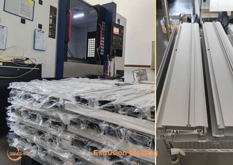
Key Takeaways for Extrusion Part Optimization
1. Structural design is the core of extrusion molding quality: adhere to uniform wall thickness, rounded corners, symmetrical cross-section, and reasonable aspect ratio to eliminate inherent molding risks from the source.
2. Most extrusion defects are caused by the combination of unreasonable design, unstable process parameters, and die wear. Optimizing part structure can reduce 60% of common molding problems.
3. Strict raw material pretreatment, real-time parameter stabilization, and regular die maintenance are essential to improve profile consistency and reduce scrap rates.
Frequently Asked Questions
Q1:What causes uneven wall thickness in extrusion profiles?
A:Main reasons include unbalanced die flow, misalignment of die parts, abrupt cross-section changes, unstable haul-off speed, and inconsistent melt plasticization.
Q2:Why do longitudinal lines and scratches appear on the profile surface?
A:It is caused by die surface wear, rust, residual material buildup, or turbulent flow due to improper die entry angle.
Q3:What leads to surface matte roughness and local bulges?
A:Poor plasticization, raw material impurities, unstable screw feeding, and unsmooth melt flow will cause surface roughness and local bulges.
Q4:How do internal voids, bubbles and porosity form in extrusion parts?
A:They are mainly caused by moisture in raw materials, trapped air, insufficient degassing, unstable extrusion pressure, and fast cooling shrinkage.
Q5:What is Die Swell in extrusion?
A:Die swell is the natural expansion of melt after exiting the die opening due to shear stress release. It will make the profile dimension larger than the die size.
Q6:Why should we avoid abrupt wall thickness changes?
A:Abrupt thickness changes cause unbalanced melt flow, shear rate fluctuation, uneven shrinkage, and finally lead to warpage, dimensional deviation and poor surface quality.
Q7:What is the best profile cross-section design for extrusion?
A:Symmetrical and balanced cross-section with uniform wall thickness, smooth transitions, and no sharp corners or abrupt changes.
Q8:How to reduce extrusion dimensional deviation?
A:Stabilize extrusion temperature and speed, balance die flow, ensure correct die alignment, maintain uniform wall thickness, and control cooling and haul-off consistency.
Q9:What is the difference between laminar flow and turbulent flow in extrusion?
A:Laminar flow is smooth, stable and uniform for high-quality extrusion. Turbulent flow is chaotic, causing scratches, streaks, roughness and internal defects.
Q10:What are the key takeaways for extrusion optimization?
A:
10.1. Keep symmetrical & balanced cross-section and uniform wall thickness.
10.2. Avoid abrupt transitions and sharp corners.
10.3. Ensure stable plasticization, feeding, temperature and haul-off.
10.4. Maintain clean, smooth and well-aligned die.
10.5. Avoid turbulent flow and control die swell.