Gears transfer motion and torque through tooth contact. That simple purpose hides a demanding manufacturing problem: the bore or shaft, locating faces, tooth flanks and mounting references must work as one system. A gear can have an acceptable outside diameter and still run poorly because pitch, profile, helix, tooth thickness, runout or datum relationships do not match the design intent.
For this reason, gear machining should never begin with a process name alone. A request for a “precision gear” is incomplete until the drawing defines the gear geometry, functional references, tolerance system, material condition, heat treatment, surface requirements and inspection method. The process route can then be selected from hobbing, shaping, power skiving, form milling, five-axis milling, broaching, grinding, honing or another justified operation.
This guide focuses on cylindrical spur and helical gears and on practical manufacturing decisions. Bevel, hypoid, worm, face and molded gears require their own geometry, tooling and standards. For surrounding capabilities, see Samshion’s CNC machining services.
Define the Gear Before Selecting a Process
A manufacturer needs enough information to reconstruct both the nominal tooth geometry and the acceptance criteria. A 3D model is useful for packaging and blank features, but it may not communicate the complete gear specification.
Essential Gear Data
The drawing or controlled specification should identify the gear type and the applicable system. Typical inputs include:
- Number of teeth
- Normal or transverse module, or diametral pitch
- Pressure angle and helix angle
- Hand of helix for helical gears
- Profile shift or addendum modification when applicable
- Reference diameter, outside diameter and root-related limits
- Face width and required tooth modifications
- Bore, keyway, spline, hub, shoulders and mounting faces
- Tooth thickness, measurement over pins or span measurement
- Backlash intent as an assembly requirement, not a vague gear-only promise
- Material, heat treatment, hardness and case-depth requirements
- Gear tolerance class and the exact referenced standard and edition
- Required inspection characteristics, sampling and report format
Do not mix values from metric module and diametral-pitch systems without a controlled conversion. Do not assume a standard pressure angle, helix hand or tooth modification from a model image. If the customer supplies a mating gear, center distance and contact requirement, those inputs should be reviewed together.
Tolerance Class Is Not a Performance Guarantee
ISO 1328-1 establishes a flank-tolerance classification system for individual cylindrical involute gears. It addresses deviations such as pitch, profile and helix within its stated scope. The standard also cautions against using the tolerance values of an unassembled gear as a direct prediction of assembly performance.
That distinction matters. Noise, load distribution, transmission error, durability and backlash also depend on housing geometry, bearings, shafts, center distance, alignment, lubrication, tooth modifications, load and operating temperature. Select the tolerance class through design analysis and application experience. Do not assign a class merely because a process is advertised as “high precision.”
Understand the Main Gear Machining Processes
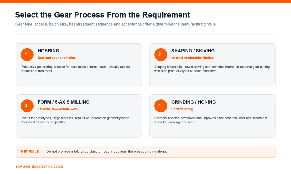
|
Process |
Typical fit |
Main strength |
Main limitation or control point |
|
Hobbing |
Accessible external spur and helical gears |
Continuous generating action and strong production capability |
Cannot normally cut an internal gear and needs axial or radial tool clearance |
|
Shaping |
Internal and external gears, teeth near shoulders |
Versatile pinion-cutter process with useful access |
Reciprocating action can be slower and requires careful cutter and stroke control |
|
Power skiving |
Internal or external cylindrical gears on capable machines |
Continuous process with high productivity and possible single-setup integration |
Requires synchronized machine motion, stiffness, accurate setup and application-specific tooling |
|
Form or five-axis milling |
Prototypes, repairs, large modules and low quantities |
Flexible use of general CNC equipment and programmable geometry |
Indexing, tool-path, cutter form and machine accuracy require careful validation |
|
Broaching |
Stable, higher-volume internal forms |
Fast cycle after tooling is established |
Dedicated tooling, access and economic volume are required |
|
Grinding |
Hardened gears requiring controlled flank correction |
Can improve selected profile, helix, pitch and surface characteristics |
Higher cost, thermal risk and a need for suitable grinding stock and datum control |
|
Honing |
Selected hard-finished production gears |
Can improve flank condition, noise behaviour and productivity |
Not a universal replacement for correcting large geometric errors |
Gear Hobbing
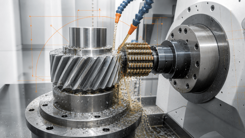
Hobbing is a generating process in which the hob and workpiece rotate in a synchronized relationship. It is widely used for external spur and helical gears because the cutting action is continuous and can be productive. Cutter design, workpiece data, machine synchronization, setup stiffness, feed direction and chip evacuation all influence the result.
Hobbing normally requires clearance for the cutter to travel across the tooth width. A nearby shoulder, flange or obstructing feature may prevent complete generation. The blank and fixture must also provide reliable rotational location and support. Hobbing by itself does not guarantee a particular tolerance class or roughness; the machine, hob quality, setup, material, wear state and inspection evidence define the demonstrated capability.
Gear Shaping
Gear shaping uses a reciprocating pinion-type or rack-type cutter with generating motion. It can produce external or internal teeth and is useful where a hob cannot pass a shoulder. Cutter runout, stroke position, relief, synchronization, rigidity and chip clearance must be controlled.
Shaping may be a strong choice for internal gears or mixed gear families, but the process route must consider cycle time, cutter life and the distance between the tooth end and nearby geometry. The designer should provide tool approach and overtravel whenever possible.
Power Skiving
Power skiving combines crossed tool and workpiece axes with synchronized rotation to create a continuous cutting action. It is used for internal and external cylindrical gears and splines. Sandvik Coromant describes power skiving as a continuous process whose axis intersection and rotational relationship are central to productivity, and notes its ability to machine close to shoulders in suitable applications.
The process can integrate turning, datum creation and gear cutting on a multi-task or dedicated machine, reducing handling and datum transfer. However, it is not automatically correct for every internal gear. Machine synchronization, spindle stiffness, tool overhang, cutter design, collision clearance and chip evacuation must be validated for the exact component.
Form Milling and Five-Axis Gear Milling
Form milling uses a cutter whose profile contributes directly to the tooth space. CNC indexing positions each space. Modern multi-axis strategies can generate or approximate complex flank geometry through programmed tool paths. These approaches are valuable for prototypes, repairs, large gears, low quantities or unusual geometries where dedicated hobs or shaper cutters are uneconomical.
Flexibility does not eliminate verification. The programmed geometry, tool radius, indexing accuracy, machine kinematics, datum transfer and flank scallop must be reviewed. A model-only tool path should be checked against the actual gear definition and measurement method.
Broaching
Broaching can manufacture selected internal gears or splines efficiently once a dedicated tool and stable blank are available. The tool passes progressively sized cutting sections through the bore. It can offer excellent cycle time in production but requires suitable through-access, strong tooling investment and controlled blank preparation. It is rarely the first choice for frequently changing prototypes.
Gear Grinding and Honing
Grinding is commonly used after hardening when the drawing requires correction of selected flank deviations, controlled tooth modifications or an improved surface condition. Threaded-wheel and profile-grinding methods have different application ranges. Grinding stock must be planned before heat treatment, and the locating datums used for hard finishing must remain functional.
Grinding can also create burn, tensile thermal damage, cracks or an altered surface layer if wheel condition, dressing, coolant and power are not controlled. Visual appearance alone cannot prove a sound ground surface. The inspection plan may need dimensional, surface and metallurgical checks based on risk.
Gear honing can improve selected hardened tooth surfaces and production performance. Gleason’s in-process gear inspection overview describes integrated systems that measure profile, lead and pitch and feed corrections back to hard-finishing equipment. This illustrates a broader principle: finishing results should be connected to measured deviations, not assumed from the machine name.
Where Wire EDM Fits
Wire EDM cuts conductive material with a traveling wire. It may be useful for prototypes, thin plates, special internal profiles, tooling, gauges or unusual features when access and geometry suit the process. It is not the normal universal solution for micro gears, non-involute gears or production gear teeth.
Wire path, start-hole access, taper capability, recast layer, surface integrity, corner behaviour, part thickness, wire diameter and cycle time all matter. A wire-cut tooth profile also needs the same dimensional definition and inspection plan as a cut or ground gear. Use EDM only after a process comparison, not as a shortcut around missing gear data.
Match the Process to External and Internal Gears
External gears provide more cutter access, so hobbing, milling, shaping, skiving and grinding may all be candidates. Internal gears remove that access. Hobbing is generally not available for a conventional internal tooth form, while shaping, power skiving, broaching and selected grinding methods may be appropriate.
Shoulder distance is often as important as whether the gear is internal or external. A cutter needs approach, working engagement and overtravel. The root fillet and cutter tip must also be compatible. If a gear is placed immediately beside a large flange, the designer may force a slower or more expensive process. A relief groove, increased spacing or separate gear-and-shaft assembly can open better manufacturing routes.
|
Geometry question |
Manufacturing consequence |
|
Is the gear external or internal? |
Determines whether hobbing is available and changes cutter access |
|
Is there a shoulder near the teeth? |
Limits tool diameter, approach, overtravel and process choice |
|
Is the gear integral with a shaft? |
Changes workholding, datum transfer and hard-finishing access |
|
Is the face width long relative to support? |
Increases deflection, helix control and fixture demands |
|
Are roots, tips or flanks modified? |
Requires explicit geometry and compatible tool or program data |
|
Is the bore finished before heat treatment? |
Runout may change after hardening and require a later datum operation |
Plan Material and Heat Treatment as One Route
Gear material selection belongs to the design engineer because tooth-root strength, contact fatigue, wear, impact, temperature, corrosion and lubrication must be rated. Common families include through-hardened steels, carburizing steels, nitriding steels, stainless steels, cast irons, bronzes, aluminium alloys and engineering plastics. Each family changes blank production, machining, heat treatment, distortion and finishing. Use the manufacturing materials guide to confirm available material families before the detailed gear review.
AGMA’s metallurgical specification overview identifies metallurgical quality characteristics important to steel and cast-iron gearing and connects them to heat-treatment method and quality level. The practical lesson is to specify more than a generic alloy name.
Soft Cutting Before Heat Treatment
The blank is commonly turned, bored and faced before teeth are generated in the soft condition. The process may leave controlled material on bores, faces or flanks for later finishing. Stock values must be based on size, geometry, heat-treatment experience and required correction. One fixed grinding allowance does not fit every gear.
Heat Treatment and Distortion
Carburizing, induction hardening, nitriding and through hardening produce different cases, hardness patterns and dimensional changes. Distortion may appear as bore movement, face runout, tooth-lead change, pitch variation or ovality. Fixture design, loading, material history, section balance and heat-treatment control all contribute.
Grinding is not the only response, and it cannot repair unlimited distortion. The route may include pre-heat-treatment control, press quenching, datum restoration, selective grinding, honing or a design change. Agree on which surfaces will be used to locate the gear after heat treatment and how much correction remains available.
Establish Functional Datums and Workholding
The teeth operate relative to the mounting bore, shaft or bearing journals and to the gear faces. Those relationships should drive the datum scheme. Locating the gear from an unrelated outside diameter may create an acceptable tooth form that runs eccentrically in assembly.
Prepare the Blank
Control the blank bore, faces, concentric diameters, chamfers and stock before tooth cutting. Remove burrs and contamination from locating surfaces. For thin-rimmed gears, chucking pressure can distort the blank during cutting and measurement. For shaft gears, support and overhang can affect runout and helix.
The CNC fixturing and datum-transfer guide explains the general relationship between locating, clamping and repeatability. Gear work adds the need to preserve the tooth-to-mounting-axis relationship through heat treatment and finishing.
Verify Setup Before Production
Check arbor or chuck runout, face seating, cutter runout, center distance, tool alignment and program data. Cut and inspect a first-off part before releasing a batch. If the machine supports compensation, base corrections on a stable measurement system and a documented method. Do not chase random measurement noise by continually changing offsets.
Control Tool Wear, Burrs and Surface Integrity
Gear cutters are form-critical tools. Wear or damage can change the tooth profile, root, pitch consistency and surface. Record cutter identity, sharpening history, coating, setup, machine, material lot and part count. Inspect the tool and workpiece at planned intervals. Samshion’s CNC cutting tool guide explains how tool material, coating and edge geometry should be matched to the workpiece and operation.
Common warning signs include increasing profile deviation, burr growth, rising spindle load, abnormal sound, chipped cutting edges, surface tearing and inconsistent tooth thickness. Tool-life limits should come from measured trends, not a universal number of gears.
Deburring is part of the gear process, not an optional cosmetic step. Burrs can interfere with inspection, assembly, contact and lubrication. Chamfering and edge-break geometry should be specified. Avoid hand blending that changes functional flanks or destroys traceability. When a drawing also controls appearance or protective treatment, coordinate the tooth requirements with the available surface finishing options.
Inspect the Gear Against the Drawing
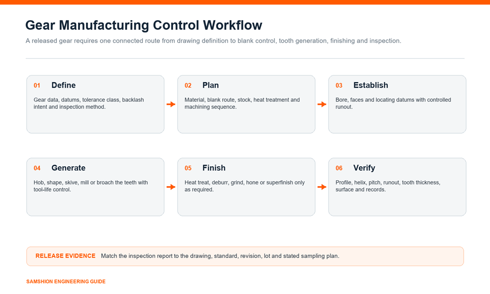
Gear inspection must match the standard, characteristic and functional risk. A caliper measurement of outside diameter cannot establish gear quality. Depending on the requirement, inspection may include:
- Tooth profile or involute deviation
- Helix or lead deviation
- Single pitch and cumulative pitch deviation
- Radial or axial runout relative to the defined datum
- Tooth thickness, span measurement or measurement over pins
- Bore, face, keyway and concentric feature geometry
- Surface texture at a defined location and direction
- Composite rolling or double-flank checks
- Contact pattern or functional rolling checks
- Hardness, case depth and metallurgical requirements
The current AGMA inspection-practice page describes tangential measurements including pitch, profile, helix and composite characteristics. Specify which report is required rather than asking for a generic “gear inspection report.”
Measurement Uncertainty and Calibration
The measurement system must be suitable for the tolerance. Equipment resolution alone does not establish capability. Artefacts, calibration, temperature, fixturing, probe condition, filtering, software settings and operator method contribute to uncertainty. A supplier and customer should agree on datum setup, evaluation length, filtering and acceptance rules before a dispute occurs.
Sampling and Traceability
Prototype gears may receive complete inspection, while stable production may use first-off, in-process and final sampling. Sampling does not remove the need for process control. Link each report to drawing revision, part number, material lot, heat-treatment lot, machine or route, inspection equipment and date. The CNC production machining guide provides the broader framework for first-off approval, process monitoring and repeat orders.
For Samshion’s broader inspection approach, see quality assurance and inspection systems.
Gear Machining DFM Guidelines
Provide Cutter Clearance
Keep shoulders, flanges and adjacent walls far enough from the teeth for the selected tool to enter and overtravel. If packaging prevents clearance, identify the restriction early so shaping, skiving, special tooling or a split assembly can be evaluated.
Use a Manufacturable Root and Relief
Root fillet and protuberance requirements must match the cutting and finishing tools. An unnecessarily small root radius can increase stress concentration and demand special tooling. Relief grooves should be designed with strength, grinding access and inspection in mind.
Avoid Unsupported Thin Rims
Thin rims can deflect during cutting, heat treatment and inspection. Review rim thickness, web symmetry, clamping location and heat-treatment distortion. If a lightweight gear is required, validate the blank and process through analysis and trials.
Separate Critical and Noncritical Requirements
Do not apply the tightest tolerance class, roughness or runout to every surface. Identify the tooth characteristics and mounting references that control function. Reasonable tolerances on noncritical blank features preserve machining options and inspection time.
Define Edge Condition and Cleanliness
Specify chamfers, burr limits, sharp-edge handling, cleanliness and corrosion protection. A tooth can pass dimensional inspection and still fail assembly because of an uncontrolled burr or debris.
The broader design for manufacturability guide explains how geometry, tolerances, materials and process access interact before production.
Troubleshooting Common Gear Manufacturing Problems
|
Symptom |
Possible contributors |
Evidence to collect |
Typical response direction |
|
Excessive runout |
Blank datum error, poor seating, heat-treatment movement or finish-datum mismatch |
Bore and face geometry, setup runout, pre/post heat data |
Restore datum control, improve seating or revise finishing sequence |
|
Profile deviation |
Cutter form or wear, alignment, program data, grinding condition |
Profile chart, tool record, setup verification |
Correct tool, alignment, dressing or program definition |
|
Helix or lead error |
Tool alignment, fixture deflection, thermal drift or machine kinematics |
Lead chart, temperature, fixture and axis checks |
Stabilize setup and correct the validated source |
|
Pitch variation |
Indexing or synchronization error, cutter damage, unstable mounting |
Pitch chart, encoder and cutter checks |
Correct machine synchronization, tool or workholding |
|
Burrs or edge breakout |
Dull tool, unsuitable edge geometry, exit condition or material behaviour |
Burr location, tool wear and path direction |
Improve cutter condition, chamfer process, support or path |
|
Grinding burn |
Excess heat, dull wheel, poor dressing or coolant delivery |
Power trend, etch or metallurgical evidence |
Correct wheel, dressing, stock, feed and coolant system |
|
Noisy assembly |
Gear deviations, center distance, alignment, backlash, bearing or lubrication issue |
Gear reports plus assembly geometry and contact data |
Diagnose the complete system rather than one tooth metric |
Quote-to-Parts Workflow
- Submit controlled data. Send STEP or another suitable CAD file plus a 2D gear drawing, quantity, material, heat treatment, tolerance standard, inspection needs and delivery target.
- Review the definition. Resolve missing module or DP data, pressure angle, helix, profile modifications, datums, backlash intent and report format.
- Select the route. Compare blank production, soft machining, tooth generation, heat treatment, hard finishing, deburring and inspection.
- Approve DFM and quotation. Confirm assumptions, tooling investment, first-article plan, lead time and commercial responsibility for special testing.
- Produce and inspect the first article. Verify the chosen datums and gear characteristics before releasing the remaining quantity.
- Control production and release. Monitor tool life and measurements, complete final inspection and package gears to protect the teeth.
To begin a project, upload your CAD files and gear drawing.
Information to Include With a Gear RFQ
|
RFQ item |
Why it matters |
|
3D model and controlled 2D drawing |
Connects blank geometry to gear-specific acceptance requirements |
|
Gear system and complete tooth data |
Prevents assumptions about module, DP, pressure angle, helix and modification |
|
Datum scheme |
Defines how tooth accuracy relates to the mounting axis and faces |
|
Material and supplied condition |
Controls blank route, machinability, heat treatment and distortion risk |
|
Heat treatment and hardness |
Determines sequence, stock and hard-finishing requirements |
|
Standard, tolerance class and edition |
Establishes a common acceptance language |
|
Inspection characteristics and report |
Ensures the supplier quotes the correct measurement method |
|
Quantity and forecast |
Determines whether flexible CNC cutting or dedicated tooling is economical |
|
Mating information and functional risks |
Supports review of backlash, contact and assembly behaviour |
|
Packaging and preservation |
Protects teeth, finished surfaces and traceability during shipment |
Frequently Asked Questions
What is the best process for machining gears?
There is no single best process. Hobbing is often productive for accessible external gears; shaping and power skiving can address internal gears; milling offers flexibility for prototypes and uncommon work; grinding or honing may be used after heat treatment. Select from the drawing, access, material, quantity, heat-treatment route and inspection requirement.
Does gear hobbing automatically achieve a certain ISO class?
No. Hobbing capability depends on machine condition, hob quality, setup, blank, material, tool wear, thermal stability and measurement. A supplier should demonstrate the required characteristics on the actual process rather than promise a class from the process name.
Can a five-axis machining center make a gear?
It can machine selected gears through form or programmed flank milling, especially for prototypes, low quantities and large or unusual geometry. The tooth definition, indexing, cutter geometry, machine kinematics and inspection still require validation. Dedicated generating processes may be more productive for repeat production.
When is power skiving useful?
Power skiving is useful for suitable internal and external cylindrical gears when synchronized machine capability, cutter access, stiffness and quantity justify it. It can reduce handling by combining operations, but the exact component must be checked for collision, shoulder clearance and tool overhang.
Is gear grinding always required after heat treatment?
No. The need depends on the heat-treatment distortion, required flank tolerances, surface condition and application. Some gears are used after controlled heat treatment and finishing by another method. Others require grinding or honing. The route should be defined before the blank is machined so appropriate stock and datums remain.
What should a gear inspection report contain?
It should identify the part and drawing revision, standard and class, measured characteristics, datum setup, equipment, results, lot or serial traceability and stated sampling. Required charts may include profile, helix, pitch and runout. Agree on the report before quotation.
Conclusion
Reliable gear machining is a controlled system, not a contest between process names. Start with complete gear data and functional datums. Select a route that fits tooth access, material, quantity and heat treatment. Preserve the mounting relationship through each setup, manage cutter condition, and verify the gear with an agreed measurement method.
This approach avoids unsupported promises about ISO class, micrometre error or surface roughness. More importantly, it produces evidence that the manufactured gear matches the drawing and is ready for evaluation in the complete transmission.