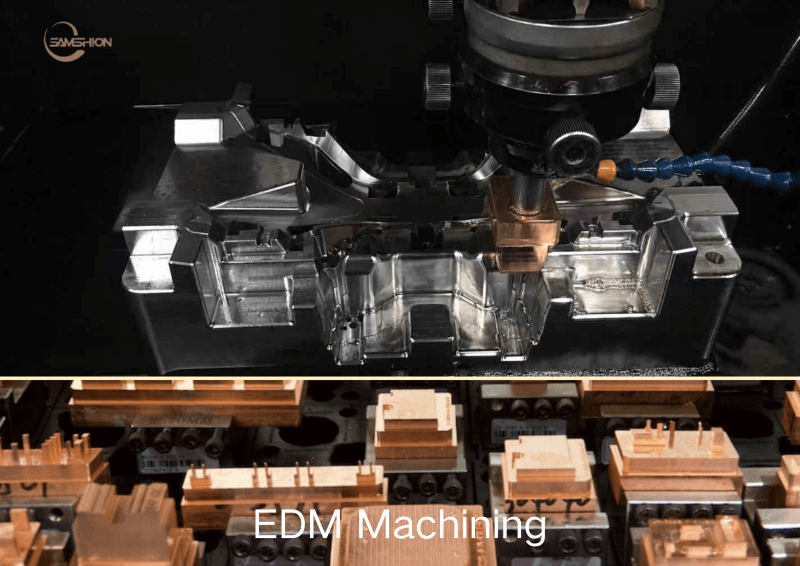
Electrical discharge machining removes electrically conductive material through a controlled series of electrical discharges across a small working gap. Because the tool and workpiece do not cut each other through a conventional mechanical edge, EDM can produce hardened-metal features, narrow slots, fine holes and detailed cavities that may be inefficient or inaccessible to milling, turning or grinding.
That advantage does not make EDM a universal precision shortcut. Wire EDM, sinker EDM and hole-drilling EDM create different forms. Each requires its own access, tooling, dielectric system, control strategy and inspection plan. The achievable geometry, tolerance, roughness and surface integrity depend on the machine, workpiece, setup, feature size, thickness or depth, discharge conditions, flushing, temperature, consumables and number of finishing operations.
The best manufacturing route usually combines processes. Conventional CNC machining services remove accessible stock efficiently and establish datums. EDM is then reserved for features that justify its slower, specialized cycle. This guide explains how to select and control that route without relying on a fixed setting, guaranteed micrometre value or unsupported cost-saving percentage.
What Is EDM Machining?
In an EDM system, the machine controls the relative position of an electrode and a conductive workpiece while a dielectric medium occupies the working gap. The generator applies pulsed electrical energy. When conditions in the gap permit a discharge, localized energy removes a very small amount of material. The dielectric and flushing system help cool the zone, restore insulation between pulses and carry debris away.
EDM is often described as non-contact machining. This means it does not use a conventional cutting edge pressing into the workpiece. It does not mean that setup forces and process disturbances disappear. Wire tension, fluid pressure, electrode motion, clamping, thermal change, released residual stress, debris and unstable discharges can still influence the result.
The Makino overview of EDM applications distinguishes sinker EDM, wire EDM and EDM hole drilling. Mitsubishi Electric also separates wire-cut and die-sinking EDM systems. These distinctions are the first decision in process planning.
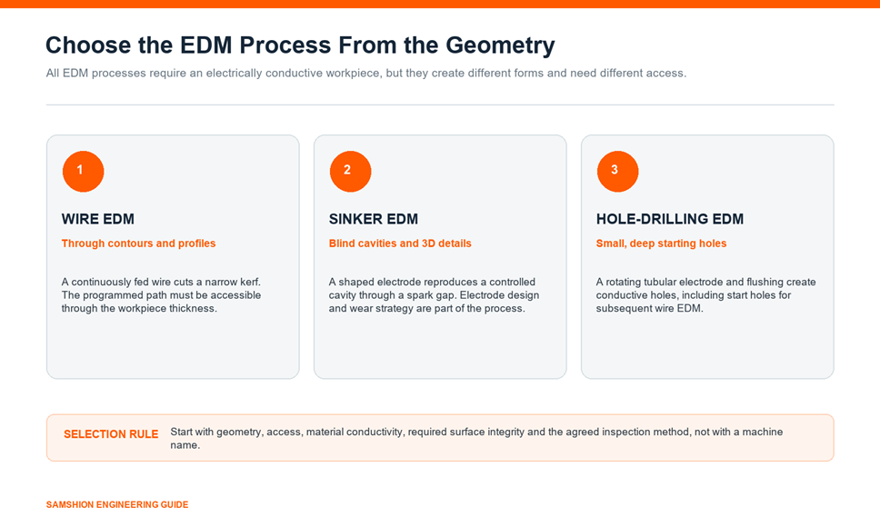
Choose Wire, Sinker or Hole-Drilling EDM
|
EDM process |
How it creates geometry |
Strong application fit |
Essential access or tooling |
Important control point |
|
Wire EDM |
A continuously fed wire follows a programmed path through a narrow kerf |
Through profiles, punches, dies, inserts, slots and selected tapers |
A through path or start hole, plus clearance for wire guides and flushing |
Wire path, offset, thickness, guide condition, tension, corner control and skim strategy |
|
Sinker EDM |
A shaped electrode advances into the workpiece and reproduces a cavity through a spark gap |
Blind cavities, ribs, text, mold details and shapes that cannot be reached by a rotating cutter |
A manufactured electrode, holder, reference system and an approach direction |
Electrode undersize, wear, orbit, flushing, polarity and rough-to-finish electrode plan |
|
Hole-drilling EDM |
A rotating tubular electrode uses internal flushing to erode a hole |
Small deep holes, turbine cooling holes, start holes and difficult conductive alloys |
Electrode approach, flushing path and a stable guide |
Breakthrough, taper, electrode wear, debris evacuation and exit condition |
When Should You Choose Wire EDM?
Wire EDM feeds a wire electrode from a spool through upper and lower guides. The wire does not act like a saw blade. The machine maintains a controlled gap while the programmed motion creates a kerf. This process is especially useful for through contours in hardened steels, carbides and other conductive materials.
Wire diameter is not the same as kerf width or minimum internal radius. The discharge gap and process offset contribute to the cut size, while corner control, thickness, wire behavior and finishing passes affect the practical feature. A designer should not specify an internal corner exactly equal to a nominal wire radius without confirming the supplier’s qualified capability.
The workpiece path must be accessible. A completely enclosed internal passage cannot normally be produced by wire EDM because the wire must enter and remain threaded between its guides. A start hole may be drilled by EDM or another process, but the complete contour and resulting slug still require a planned removal route. For defect diagnosis, use Samshion’s separate Wire EDM troubleshooting guide.
Sinker EDM Machining
Sinker EDM uses a formed electrode, commonly made from graphite, copper or another qualified material, to generate a blind cavity or detail. The electrode is not simply a full-size copy of the cavity. Its geometry must account for the intended discharge gap, orbit or motion strategy, electrode wear, finish stage and any separate roughing and finishing electrodes.
A deep rib, fine corner or text feature can concentrate wear or make debris evacuation difficult. Electrode relief, venting, jump motion, side flushing, submerged flushing and staged depth may be considered. These choices are application-specific. Excessive flushing pressure can disturb a weak feature, while inadequate debris removal can cause unstable discharges, arcing or localized damage.
Electrode accuracy becomes part of the workpiece error budget. Datum transfer between electrode machining, presetting, measurement and the EDM machine must be controlled. The dedicated EDM electrode manufacturing guide explains electrode material, workholding and verification in more detail.
Hole-Drilling EDM
Hole-drilling EDM uses a rotating tubular electrode with dielectric flushing through the tube. It is often chosen for small, deep holes in conductive materials and for wire-EDM start holes. It can also support cooling-hole applications where geometry, material and acceptance requirements suit the process.
The operation still has practical limits. Hole diameter, depth-to-diameter ratio, breakthrough condition, electrode consumption, flushing pressure, guide wear and workpiece material affect size, taper and position. If a drilled start hole will be consumed by a later wire cut, its location and diameter should support reliable threading without encroaching on a critical finished surface.
Define the Requirement Before Selecting Settings
A complete request for EDM should identify function, geometry and acceptance criteria. A statement such as “EDM to 0.005 mm” is not enough. The manufacturer must know what dimension carries that tolerance, which datums control it, where it applies, and how the result will be measured.
|
Required input |
Why it matters to EDM planning |
What to clarify |
|
3D model and controlled 2D drawing |
The model defines nominal form; the drawing communicates acceptance |
Revision, units, critical dimensions, notes and any model-based definition rules |
|
Material and condition |
EDM requires electrical conductivity and responds to alloy, hardness and microstructure |
Exact grade, heat treatment, hardness, coatings and prior stress relief |
|
Datum scheme |
Setup and inspection must reference the same functional system |
Primary, secondary and tertiary datums; allowed setup surfaces |
|
Tolerances |
Tight limits may require thermal control, skim cuts, finish electrodes or additional inspection |
Which dimensions are critical and whether limits apply before or after coating |
|
Surface texture |
Roughness affects discharge strategy and the number of finishing operations |
Parameter such as Ra or Rz, location, cutoff and measurement method |
|
Surface integrity |
Recast layer, microcracking or thermal alteration may matter in fatigue or safety-critical service |
Allowed condition, removal requirement, metallographic method and sampling |
|
Edge condition |
EDM can leave sharp edges, burr-like residue at starts or exits, and fragile corners |
Break-edge, radius, chamfer and protected-edge requirements |
|
Quantity and traceability |
Batch size affects fixtures, electrodes, automation and reporting |
Prototype or production volume, lot identity, certificates and record retention |
The drawing should separate functional requirements from preferences. If only one sealing edge needs a fine finish, do not assign that finish to every discharged surface. If one profile controls assembly, identify it rather than placing a universal title-block tolerance over unrelated geometry. A focused specification often reduces cycle time without weakening function.
Understand the EDM Process Parameters
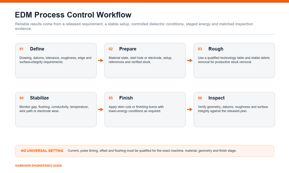
EDM technology tables supplied with a machine provide validated starting conditions for combinations of material, wire or electrode, thickness or depth, roughness target and process stage. These tables are more reliable than a universal online recipe. Final conditions should be confirmed through the machine builder’s guidance, controlled trials and inspection.
|
Variable |
General process influence |
Risk when poorly controlled |
Planning response |
|
Peak current and discharge energy |
Higher energy can increase stock removal per discharge |
Larger craters, rougher surfaces, thermal damage, wire breaks or electrode wear |
Use qualified roughing conditions, then reduce energy for finishing stages |
|
Pulse-on time |
Changes the energy delivered in each pulse |
Excessive energy density, unstable gap or surface damage |
Match material, electrode system and stage instead of maximizing one number |
|
Pulse-off time |
Allows deionization and debris movement between discharges |
Short circuits and unstable machining if the gap cannot recover |
Balance productivity with observed gap stability |
|
Servo or gap control |
Maintains the working separation |
Arcing, shorts, dimensional drift or slow cutting |
Verify responsive control and avoid overriding alarms without diagnosis |
|
Wire or electrode offset |
Compensates for electrode geometry and discharge gap |
Undersize or oversize profiles and mismatched corners |
Qualify rough and skim offsets on representative material and thickness |
|
Flushing and dielectric condition |
Removes debris, cools and helps restore insulation |
Secondary discharge, streaks, wire breaks, taper or local overburn |
Control pressure, nozzle position, filters, conductivity and cleanliness |
|
Temperature |
Changes the machine, fixture and workpiece dimensions |
Drift between setup, machining and inspection |
Stabilize machine, dielectric, part and metrology environment as required |
|
Feed, wire tension or jump motion |
Supports stable cutting or cavity clearing |
Wire lag, vibration, poor debris removal or weak-feature damage |
Use machine-specific control and confirm on critical geometry |
Energy and Surface Finish
Roughing conditions prioritize productive material removal and gap stability. Finishing conditions use lower-energy discharges and smaller corrections to improve geometry and surface condition. Mitsubishi Electric notes that wire EDM precision is commonly developed through repeated machining with lower discharge output in the finishing stage in its wire EDM control discussion.
The number of cuts or burns is not a universal quality level. A thin tool-steel insert, a thick carbide block and a tall rib cavity respond differently. The supplier should demonstrate the route using a relevant technology table, prior capability or a representative trial rather than promising that a fixed number of skim cuts always produces the same result.
Flushing, Debris and Gap Stability
EDM creates debris that must leave the active gap. When debris bridges the gap or concentrates in one region, discharges can become unstable. Wire EDM nozzle distance, workpiece steps, interrupted sections and poor sealing can alter flushing. Sinker EDM deep cavities may require planned jump motion, electrode relief or alternative flushing paths.
More pressure is not always better. High fluid force can deflect a slender wire, disturb thin walls or move a weak setup. Low flow can leave debris trapped. The correct method balances access, feature stiffness, depth and machine control. GF Machining Solutions describes adaptive wire-EDM systems that monitor spark behavior and adjust cutting parameters on its wire-cut EDM technology page, illustrating why stable control matters more than a single maximum-speed setting.
Dielectric Quality and Temperature
Wire EDM commonly uses controlled deionized water, while many sinker EDM systems use an application-specific hydrocarbon dielectric. The machine’s manuals and local safety requirements govern selection, filtration, fire protection, ventilation, maintenance and disposal.
Conductivity or resistivity, contamination, filter condition and temperature influence process stability. Do not treat dielectric maintenance as housekeeping only. A changing fluid system can alter cutting behavior and make a previously qualified offset or finish sequence unreliable. Mitsubishi Electric identifies synchronous control of machine and dielectric temperature as part of high-accuracy stability on its MX wire EDM system page.
Wire EDM Planning Boundaries
Wire EDM should be reviewed as a physical manufacturing route, not only as a 2D contour. Before selecting it, confirm five boundaries:
- The wire can enter the workpiece and remain continuously threaded between the upper and lower guides.
- The start hole and lead-in can be placed away from a critical sealing edge, precision corner or cosmetic surface.
- The specified internal radius is compatible with the wire, discharge gap, workpiece thickness and qualified corner-control strategy.
- The cut slug can be supported and removed without trapping the wire, damaging a nozzle or striking the finished profile.
- Residual-stress movement, part thickness and any programmed taper can be inspected in the released condition.
These checks establish whether wire EDM is suitable without turning this general guide into a defect-diagnosis manual. For detailed methods covering entry marks, corner errors, deformation, taper, wire breaks and thick-section variation, use Samshion’s Wire EDM troubleshooting guide.
Plan Sinker EDM From Electrode to Finished Cavity
Sinker EDM planning begins before the EDM machine runs. The electrode set, holders, reference data and inspection strategy determine whether the cavity can be located and reproduced.
Electrode Geometry and Undersize
The electrode is designed smaller than the final cavity by an amount related to the discharge gap and planned orbit. This amount is not one fixed allowance. Roughing and finishing conditions have different effective gaps, and narrow ribs or corners wear differently from broad areas. CAD/CAM, machine technology and measured electrode data should share the same offset convention.
Roughing and Finishing Electrodes
A roughing electrode can remove stock efficiently while leaving material for a finishing electrode. Separate finishing electrodes protect critical detail from accumulated rougher wear. Some applications use multiple identical electrodes at staged depths; others use orbiting or adaptive cycles. The most economical strategy depends on cavity volume, detail, finish, wear ratio, electrode cost and production quantity.
Electrode Wear and Reference Control
Wear can be volumetric, frontal or concentrated at corners. A machine may compensate using measured electrode length, programmed stages or adaptive control, but compensation cannot correct an incorrectly machined electrode or a lost datum. Electrode identification, holder repeatability, preset data and inspection status should be traceable to the job.
Deep Cavity Flushing
Deep cavities can trap gas and debris. Poor evacuation may create arcing, carbon deposits, side-wall damage or unstable cycle time. Jump cycles, vent features, relief geometry, rotation or orbit, side flushing and staged depth can help, but each may influence geometry. The plan should protect thin ribs and avoid flushing directly against a feature that can deflect or chip.
Materials for EDM Machining
The workpiece must be electrically conductive enough for the selected EDM process. Hardness alone does not prevent machining, which is why EDM is valuable after heat treatment. Conductivity, melting behavior, microstructure, thermal properties and debris all influence settings and surface response.
|
Material family |
Why EDM may be selected |
Planning concern |
|
Hardened tool and mold steels |
Detailed cavities, punches, dies and profiles after heat treatment |
Residual stress, heat-treat distortion, recast condition and start-hole route |
|
Carbide and conductive hard materials |
Conventional tools may wear rapidly or cannot form the detail |
Brittleness, edge chipping, cobalt-binder response and surface microcracking risk |
|
Titanium alloys |
Difficult conventional cutting and small precision features |
Surface integrity, thermal response and application-specific acceptance |
|
Nickel-based superalloys |
Hardened or heat-resistant features and cooling holes |
Slow cycle, recast control, electrode consumption and inspection |
|
Copper alloys |
Electrodes, electrical parts and precision profiles |
High conductivity changes technology selection and can affect cutting stability |
|
Aluminum alloys |
Selected fine profiles and tooling details |
Rapid energy response, debris, surface condition and distortion of thin sections |
|
Graphite |
Common sinker electrode material, not a normal metallic workpiece claim |
Dust control during electrode machining, grade consistency and edge strength |
Use the exact alloy and heat-treatment state in the RFQ. A generic request for “steel” does not support a dependable technology choice. Samshion’s manufacturing materials guide can help identify the starting grade, but project-specific conductivity and surface-integrity requirements still need review.
EDM Accuracy, Tolerance and Thermal Stability
EDM accuracy is a system result. Axis performance, guide or electrode condition, setup, offsets, workpiece movement, dielectric, temperature, calibration, feature geometry and inspection uncertainty all contribute. A machine brochure capability achieved under defined test conditions is not automatically the tolerance for every customer part.
|
Error source |
Typical effect |
Control method |
|
Datum or fixture error |
Whole profile shifted or rotated |
Establish functional references, verify setup and limit datum transfers |
|
Wire-guide or electrode-holder condition |
Taper, location error or inconsistent cavity |
Inspect, clean, calibrate and replace worn components |
|
Offset mismatch |
Uniform size error |
Control technology revision, material, thickness and cut stage |
|
Thermal drift |
Time-dependent dimensional change |
Stabilize machine, dielectric, workpiece and metrology environment |
|
Residual-stress release |
Bow, twist or profile movement |
Plan material condition, roughing sequence, tabs and stress relief |
|
Unstable flushing |
Local overcut, lines, wire breaks or slow cycle |
Verify nozzle position, filters, conductivity and debris path |
|
Electrode wear |
Loss of depth, corner or detail |
Use wear strategy, duplicate electrodes and measured compensation |
|
Measurement method |
Conflicting acceptance results |
Agree datums, instrument, uncertainty, temperature and reporting method |
For close tolerances, inspection should occur after the part reaches a stable temperature. Measurement against a different datum system can make a good profile appear shifted or hide a setup error. Critical characteristics may require a CMM, optical comparator, vision system, profile measurement, calibrated pins, surface-roughness instrument or metallography. Samshion’s quality assurance system explains the broader inspection and traceability framework.
Control EDM Surface Integrity
EDM removes material through localized thermal events. The resulting surface can include resolidified material, often called a recast or white layer, along with craters, residual stress or microcracking depending on energy, material and process stability. It is inaccurate to say EDM creates no heat-affected surface simply because the operation has low mechanical cutting force.
Roughing conditions generally create a more pronounced thermal surface than qualified finishing conditions. Skim cuts or finish burns may reduce roughness and altered-layer severity, but no universal layer thickness applies to every alloy and machine. A visually smooth surface is not proof that a metallurgical requirement has been met.
|
Surface requirement |
Suitable verification |
Important limitation |
|
Roughness |
Calibrated profilometer using the specified parameter and cutoff |
Ra alone does not describe every peak, crack or altered layer |
|
Recast-layer condition |
Prepared cross-section and metallographic evaluation |
Sampling must represent critical surfaces and process stages |
|
Microcracking |
Metallography or another specified nondestructive/destructive method |
Detection limit and orientation must be agreed |
|
Edge integrity |
Magnified visual or optical inspection |
Fragile corners may chip during cleaning or handling |
|
Dimensional form |
CMM, vision, comparator or form measurement |
Instrument uncertainty and datum setup must fit the tolerance |
Postprocessing may include polishing, lapping, grinding, honing, blasting or another approved method when the drawing requires removal or modification of the EDM surface. Do not add a finish by habit. It can round edges, alter size or remove texture. Select the method from function and verify the final condition. For downstream options, see Samshion’s surface-finishing guide.
Improve EDM Productivity Without Sacrificing Control
EDM cost is driven by programming, setup, electrode or wire consumption, machine time, dielectric maintenance, inspection, risk and any secondary finishing. The fastest route is not always the lowest-cost route if it creates wire breaks, unstable burns, rejected surfaces or repeated inspection.
Remove Accessible Stock With CNC First
Use milling, turning, drilling or grinding for accessible bulk removal when these processes are technically appropriate. Leave controlled stock for EDM on features that need its access, hardness independence or fine geometry. This hybrid route can reduce EDM time, but the roughing process must preserve reliable datums and enough stock for the finishing path.
Use Qualified Technology, Not Maximum Power
Begin with the machine builder’s technology for the actual wire or electrode, workpiece material, thickness or depth, and finish stage. Record deviations and results. If productivity improvement is required, change one controlled factor at a time or use a designed experiment. A universal instruction to increase current can trade cycle time for roughness, wear, wire reliability or surface damage.
Prepare Work Offline
Programming, electrode manufacture, fixture preparation, presetting, material verification and inspection planning can occur while the machine is cutting. Standard holders and controlled coordinate data reduce repeated alignment. Automation is useful only when restart, wire threading, electrode management, dielectric condition, alarms and part handling are robust.
Group Compatible Work
Batching jobs can reduce setup and warm-up losses when they use compatible material, wire or electrode, dielectric condition and inspection. Do not group parts solely because they fit on the table. A mixed setup can increase risk if one loose slug, weak feature or flushing restriction affects the other workpieces.
Maintain the Process System
Wire guides, contacts, filters, resin, pumps, dielectric, seals, electrode holders and calibration all influence stability. Planned maintenance is a production control, not just a service activity. Monitor wire breaks, short circuits, electrode consumption, cycle deviation and dimensional trend to detect deterioration before rejection.
|
Cost driver |
Poor shortcut |
Better control |
|
Machine time |
Use EDM for all stock removal |
Rough accessible geometry conventionally and reserve EDM for justified features |
|
Consumables |
Select the cheapest wire or electrode without testing |
Qualify material, grade and geometry against stability and total cycle cost |
|
Setup |
Re-reference every component manually |
Use controlled datums, standard holders and offline presetting |
|
Finishing |
Apply the finest finish everywhere |
Restrict fine roughness and surface-integrity requirements to functional surfaces |
|
Inspection |
Inspect only after the entire batch |
Verify setup and first article, then use a risk-based in-process plan |
|
Rework |
Override alarms and continue |
Diagnose debris, flushing, contact, offset, stress or consumable condition |
Control General EDM Process Problems
Do not respond to every EDM problem by increasing or decreasing current. First determine whether the symptom is geometric, thermal, electrical, fluid-related, electrode-related, measurement-related or caused by the incoming workpiece.
|
General symptom |
Possible causes to investigate |
Controlled response |
|
Incorrect dimensions |
Wrong offset, thermal drift, datum error, electrode error or incorrect technology revision |
Verify references, temperature, electrode data, test feature and program revision |
|
Unstable discharge |
Debris trapping, dielectric contamination, unsuitable energy or inadequate gap recovery |
Review dielectric condition, debris path and the qualified machine technology |
|
Slow sinker burn |
Poor cavity evacuation, unsuitable jump cycle, electrode wear or incorrect roughing strategy |
Review cavity access, electrode geometry, wear record and staged burn plan |
|
Cavity detail loss |
Electrode wear, incorrect undersize, damaged electrode or excessive roughing energy |
Measure the electrode, verify its stage and use a dedicated finish electrode when justified |
|
Roughness not achieved |
Insufficient finishing stages, contamination, unstable gap or incorrect measurement |
Confirm the finishing sequence and profilometer method on the specified surface |
|
Excessive recast condition |
High discharge energy, unstable processing or an incomplete finishing route |
Review energy stages and verify the specified surface-integrity method |
Preserve the machine, program revision, technology condition, electrode or wire specification, dielectric readings, setup, alarms and inspection results. A repeatable root-cause investigation is more valuable than an undocumented parameter change that appears to work once. Wire-specific symptoms such as entry marks, corner errors, top-to-bottom variation, wire breaks and deformation are intentionally covered in the separate Wire EDM troubleshooting guide.
DFM Guidelines for EDM Parts
- Use wire EDM for through-accessible contours and sinker EDM for justified blind cavities. Do not draw an inaccessible feature and assume the process can reach it.
- Specify an internal radius that reflects wire, gap, corner behavior or electrode strength. Confirm unusually small corners early.
- Provide a start-hole and slug-removal strategy for closed wire-cut profiles.
- Keep thin walls and fragile ribs supported through roughing and stress release.
- Identify functional datums that survive heat treatment and all setups.
- Separate critical tolerance and roughness requirements from ordinary surfaces.
- State whether dimensions apply before or after coating, polishing, heat treatment or other finishing.
- Identify any recast-layer, microcrack or surface-integrity acceptance requirement explicitly.
- Provide access and relief for sinker electrodes, flushing and holder clearance.
- Avoid broad claims such as zero taper, zero recast or sharp corners without a measurable limit and method.
For a wider manufacturing review, use Samshion’s DFM guide. EDM feasibility should be reviewed together with the preceding machining, heat treatment and final inspection rather than as an isolated operation.
EDM Quality Control and Release Plan
|
Stage |
Control |
Record or evidence |
|
Contract review |
Confirm model, drawing, revision, material, datums, tolerance, roughness and surface integrity |
Released requirement checklist |
|
Incoming material |
Verify identity, condition, hardness and prior processing as required |
Certificate, inspection or traceability record |
|
Setup approval |
Confirm fixture, datum, start hole, electrode or wire path and consumables |
Setup sheet and first-reference check |
|
First article |
Inspect critical location, size, form and surface before full production |
First article report and approved offset revision |
|
In-process control |
Monitor alarms, breaks, short circuits, electrode use, dielectric and dimensional trend |
Machine log and sampling results |
|
Final inspection |
Measure specified characteristics using agreed methods |
Final report linked to lot and drawing revision |
|
Nonconformance |
Contain affected material and identify root cause before restart |
NCR, disposition and corrective action where required |
The inspection report should name the characteristic, nominal value, limits, result, instrument or method, drawing revision and lot. For complex contours, a color map can help communicate deviation, but it should not replace the agreed datum alignment and numerical acceptance criteria.
Quote-to-Parts EDM Workflow
1. Submit the Technical Package
Provide STEP or another accepted 3D format, a controlled 2D drawing, material and heat-treatment specification, quantity, finish, critical surface-integrity requirements and delivery need. Upload them through Samshion’s instant quote page.
2. Review Geometry and Process Split
Engineering determines which features should be milled, turned, ground, wire cut, sinker burned or hole drilled. The review identifies start holes, electrodes, datum transfer, thin sections, slug risk and inspection access.
3. Confirm Exceptions and Acceptance
Any proposed radius change, lead-in location, finish limit, datum clarification or inspection method should be approved before production. This prevents the machine from producing nominal geometry that cannot be accepted consistently.
4. Prepare Material, Fixtures and Electrodes
Material state, rough machining, heat treatment, stress relief, electrode manufacture, holders and programs are controlled to the released revision. Critical electrodes can be measured before use.
5. Run First Article and Controlled Production
The first part or representative feature verifies setup and offsets. Production then follows the approved technology and sampling plan. Parameter changes that affect acceptance are documented.
6. Inspect, Finish and Release
Parts are cleaned, stabilized and inspected. Required polishing or surface treatment follows the drawing. Final records are linked to the correct lot and revision before shipment.
EDM RFQ Checklist
|
RFQ item |
Minimum information |
|
Geometry |
3D model plus controlled 2D drawing |
|
Conductive material |
Exact grade, condition, hardness and certification requirement |
|
Quantity |
Prototype, batch and expected repeat demand |
|
Critical features |
Datum-related dimensions, profiles, tapers, deep ribs, corners and holes |
|
Surface |
Roughness parameter and location, recast or microcrack requirement, cosmetic limit |
|
Process constraints |
Required EDM type, prohibited methods, approved lead-ins or start-hole locations |
|
Secondary operations |
Heat treatment, grinding, polishing, coating, cleaning and passivation |
|
Inspection |
Sampling, CMM or profile report, surface measurement and metallography if needed |
|
Delivery |
Required date, partial shipment and packaging needs |
Frequently Asked Questions About EDM Machining
Can EDM machine nonconductive plastics, glass or ceramics?
Standard EDM requires an electrically conductive workpiece. Some specialized research or assisted processes address selected nonconductive materials, but they should not be assumed for normal production. Plastics, ordinary glass and conventional insulating ceramics generally require another method.
Is EDM more accurate than CNC milling?
Neither process is universally more accurate. EDM can access hardened materials and geometries that challenge a rotating cutter, while CNC milling can remove accessible stock quickly and establish datums. Actual accuracy depends on the complete machine, setup, feature, temperature and inspection system. The best route often uses both.
Does EDM create perfectly sharp internal corners?
No. Wire EDM has a practical radius influenced by wire size, discharge gap and corner behavior. Sinker EDM requires an electrode that has adequate strength and an effective discharge gap. Specify a measurable radius and confirm capability for the actual depth or thickness.
How many skim cuts are required?
There is no universal number. Material, thickness, wire, machine technology, required size, form, roughness and surface integrity determine the sequence. Use a qualified technology table and verify the result on representative geometry.
Does EDM leave a heat-affected surface?
EDM is a thermal removal process and can produce a recast layer, craters, residual stress or microcracking. Severity depends on energy, material and stability. Finishing passes can reduce the altered condition, but critical requirements should be stated and verified rather than assumed.
Why does a wire EDM part move after the profile is cut?
The cut can release residual stress from material production, heat treatment, welding or rough machining. Slug weight and loss of structural continuity can also move the part. Staged cuts, tabs, stress relief, balanced roughing and controlled support may be needed.
What information reduces EDM quotation uncertainty?
Provide the model, drawing, exact material condition, quantity, functional datums, critical tolerances, roughness locations, surface-integrity requirements, start-hole or lead-in restrictions, secondary processes and requested inspection records. Clear requirements let the supplier select a defensible process instead of adding risk allowance.
Conclusion
EDM machining is most valuable when geometry, conductivity, hardness or access justifies controlled spark erosion. Reliable results do not come from a universal current, a fixed number of passes or an assumed machine accuracy. They come from choosing the correct EDM type, defining the drawing, stabilizing the dielectric and setup, controlling energy and debris, planning electrode or wire behavior, and inspecting the characteristics that matter.
Use conventional CNC operations for accessible stock removal, reserve EDM for the features that need it, and connect every finishing step to a measurable requirement. If you are preparing a conductive precision part, Samshion can review the process split, start-hole or electrode strategy, datums, surface requirements and inspection plan before production.