An O-ring does not seal because a groove merely exists. The gland must provide the intended compression while leaving appropriate volume for deformation, pressure and material behavior. Static face seals, radial seals and dynamic applications do not share one universal geometry.
Machining begins only after the seal application and gland calculation are defined. The supplier’s job is then to preserve width, depth, position, edge condition and surface texture through machining, coating and inspection.
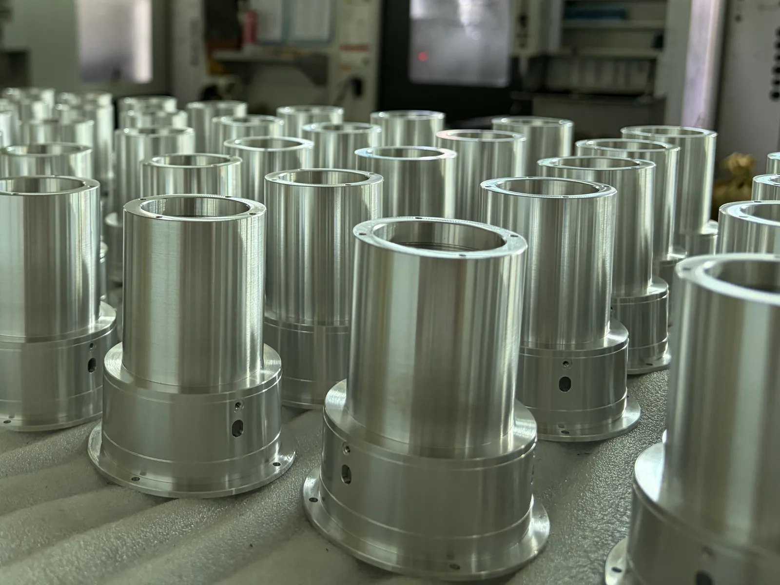
At SAMSHION we machine O-ring grooves very often, on all kinds of parts. This guide covers what to put on the drawing, how the grooves are machined and how they are checked.
Key Takeaways
- Identify the seal application before selecting gland dimensions.
- Dimension width and depth from stable functional datums.
- Protect the O-ring with suitable entry edges.
- Control toolpath witness marks and surface lay in the sealing path.
- Account for anodize, plating or other finish in final groove geometry.
Start with the Seal Application
Static face, piston, rod, reciprocating and rotary seals need different design considerations. Use the seal manufacturer’s handbook. Select the gland from a recognized seal-design source such as the Parker O-Ring Handbook ORD 5700 and then translate the chosen application requirements into the controlled part drawing.
Translate Gland Requirements into a Drawing
State width, depth, diameter or path, corner condition, finish and datums clearly.
Machine Continuous and Complex Grooves
Stable interpolation, cutter reach and entry strategy control width and witness marks. See our CNC milling services.
Allow for Coatings and Surface Treatments
Coating changes groove dimensions and edge condition. Inspect after the final specified finish. See our surface finishing services.
Verify the Finished Gland
Measure width, depth, path position, texture and local defects at more than one location. See our CNC machining surface finish options.
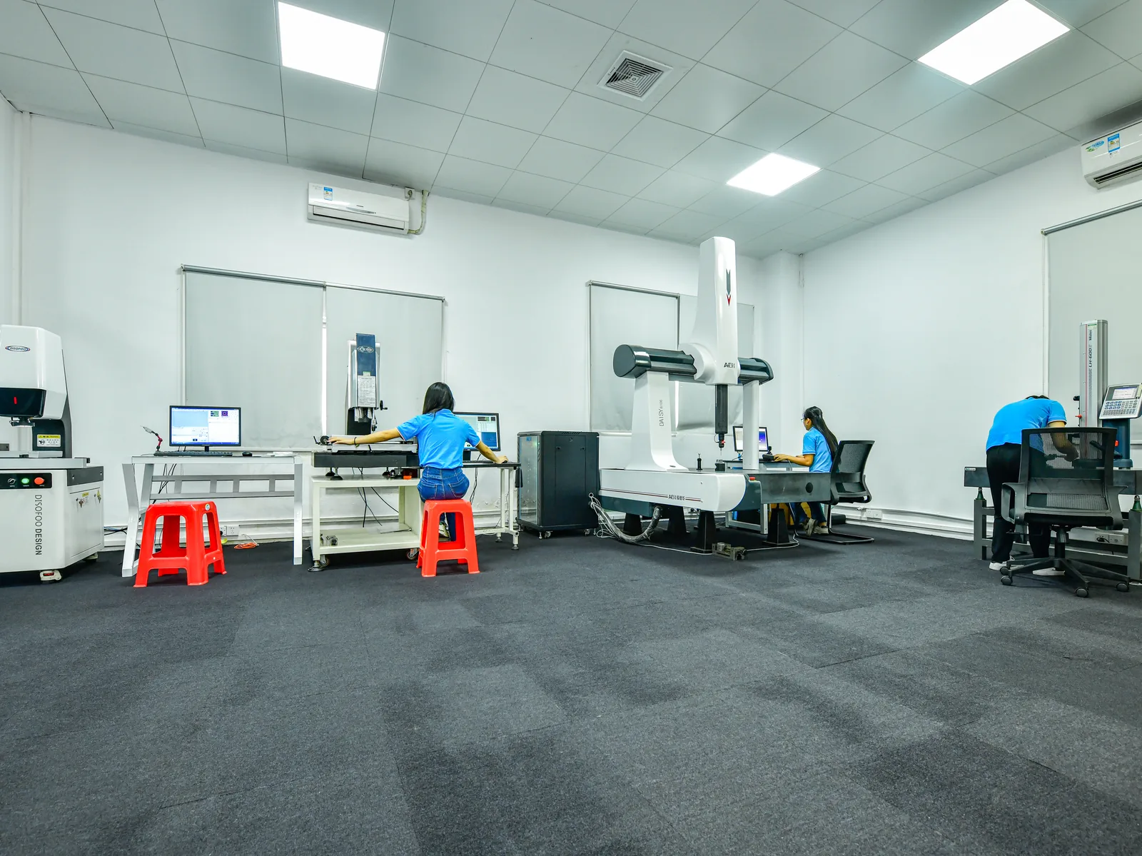
In our inspection room, groove width and depth are checked with gauges, calipers and a 2D vision measuring machine, groove position on the CMM, and surface finish with a roughness tester.
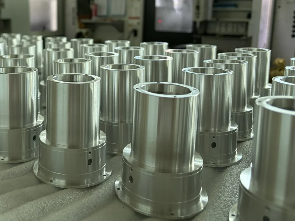
Common Design Guidelines for O-Ring Grooves
Groove sizes normally come from the seal supplier’s handbook for the chosen O-ring, which is usually sized to AS568 (inch) or ISO 3601 (metric). The following general guidelines are widely used as a starting point:
- Squeeze: roughly 15–30% of the cross-section for static seals, and roughly 10–20% for dynamic seals, where too much squeeze increases friction and wear.
- Groove fill: the O-ring should take up no more than about 85% of the groove volume, leaving room for swell and thermal expansion.
- Surface finish: around Ra 1.6 µm on the groove walls and bottom is typical for static seals; dynamic sealing surfaces that the O-ring slides on usually need a finer finish, around Ra 0.4–0.8 µm.
- Edges: small radii at the groove bottom corners, and a light edge break at the top of the groove so the O-ring is not cut during assembly.
- Lead-in chamfers: on bores and shafts the O-ring slides over, a chamfer of about 15–20° helps prevent pinching.
For what Ra values mean in practice, see surface roughness vs tolerance. For burr-free groove edges, see our deburring guide.
O-Ring Grooves on Anodized and Coated Parts
Anodizing builds up on the groove walls and bottom and changes the groove size. On Type III hard anodized parts the change is large enough to affect squeeze. State whether groove dimensions apply before or after finishing, or ask for the groove to be masked. See our anodizing guide for typical coating thickness. Untoleranced groove dimensions would otherwise follow ISO 2768-mK, which is usually too loose for a seal, so put explicit tolerances on width, depth and diameter.
Face Seal and Radial Seal Grooves
- Face seal grooves are cut into a flat face, and the O-ring is squeezed between the groove bottom and a mating cover. They are milled with an end mill following the groove path, so rectangular grooves get a corner radius at least equal to the cutter radius. For internal pressure, size the groove so the O-ring sits against the outer wall; for external pressure, against the inner wall.
- Radial seal grooves sit on a shaft (male gland) or in a bore (female gland). Shaft grooves are usually turned; bore grooves need an internal grooving tool or a milled interpolation, and the bore depth limits which tools can reach.
- Dovetail and half-dovetail grooves hold the O-ring in place on a cover that is opened often. They need a dedicated dovetail cutter and cost more to machine and inspect, so use them only when the O-ring must not fall out.
A Worked Example: Static Face Seal on an Aluminum Cover
Take a 6061 aluminum cover sealed with a 2.62 mm cross-section O-ring against internal pressure. A typical handbook groove for that size is about 3.6 mm wide and about 2.0 mm deep, which gives around 20–25% squeeze and leaves room for swell. On the drawing that becomes:
- Groove width and depth with explicit tolerances, for example ±0.05 mm
- Groove path dimensioned from the same datums as the bolt holes
- Ra 1.6 µm on the groove bottom and walls, with no radial scratches across the sealing face
- Bottom corner radius 0.2–0.4 mm, top edge broken 0.1–0.2 mm
- A note on whether the groove is masked during anodizing
With those details the groove can be milled in the same setup as the face, inspected for width and depth, and checked for scratches before finishing.
Common O-Ring Groove Mistakes
- Copying the O-ring cross-section as the groove depth. That gives zero squeeze and the joint leaks.
- Leaving groove tolerances to the general tolerance. ISO 2768 is far too loose for a seal.
- Sharp groove edges. They cut the O-ring during assembly.
- Ignoring coating build-up on anodized or plated parts.
- Radial tool marks across a face seal, which create a leak path even when Ra looks acceptable.
- Grooves too close to a bolt hole or edge, leaving a thin wall that distorts under clamping.
Frequently Asked Questions
Can one groove size work for static and dynamic seals?
Not automatically. Application, pressure, speed, compound and lubrication change the design basis.
Should an O-ring groove have sharp corners?
Follow the selected gland standard and assembly requirements; entry edges generally need protection against seal damage.
Does anodizing affect groove size?
Yes. The final geometry depends on coating build and whether the drawing controls pre- or post-finish dimensions.
Is Ra alone enough to approve a groove?
No. Local scratches, lay, waviness, width, depth and edge condition can also matter.
What tolerance should an O-ring groove have?
Typical values are around ±0.05 mm on width and depth for small grooves, but the seal supplier’s handbook for the chosen O-ring size is the reference. General tolerances are not tight enough.
Can O-ring grooves be machined in plastic parts?
Yes. Grooves in POM, PEEK, nylon and other plastics are common. Allow for the plastic moving after machining, and keep the walls next to the groove thick enough not to deflect.
Is a turned groove better than a milled groove?
For round radial seals, a turned groove usually gives a better finish and roundness. Milled grooves are used for face seals and non-circular paths.
Get an Engineering Review
Upload the CAD model and controlled drawing for an engineering review before production. When the model and drawing are ready, use upload your seal-housing drawing and include the material, quantity, finish and inspection requirements.
For a review of CNC machining O-ring grooves, send the native CAD model, controlled drawing, material specification, quantity, finishing route and required acceptance records. SAMSHION’s engineering team can return project-specific DFM questions and documented quotation assumptions before production begins.