CNC machined aluminum brackets often do more than support a component. When several assemblies attach to one bracket, its bores, mounting faces and hole patterns help establish how those assemblies fit together. A correct bore diameter alone does not confirm that a lens mount will sit in the required position relative to another mounting face.
For custom aluminum mounting brackets, define the functional interfaces first. Then agree on the machining references, surface treatment and final inspection requirements. These decisions belong together: a feature may pass inspection before finishing yet still need to be checked in its finished condition.
This guide focuses on brackets machined from solid aluminum stock. It explains what to specify and review before ordering, using a 100-piece batch of 6061-T6 infrared equipment brackets manufactured by SAMSHION to illustrate the decisions. The same questions are useful for other multi-face equipment brackets, although the answers depend on each drawing.
Start with the components that attach to the bracket
A bracket drawing should make clear which features locate another component, which carry fasteners and which simply provide clearance. Those roles can require different controls even when the holes look similar in a photograph.
For example, a clearance hole may allow a screw to pass through while a separate locating feature establishes the assembly position. A close-fitting bore may locate a mating component directly. Applying the same size tolerance to both features would not explain their different jobs.
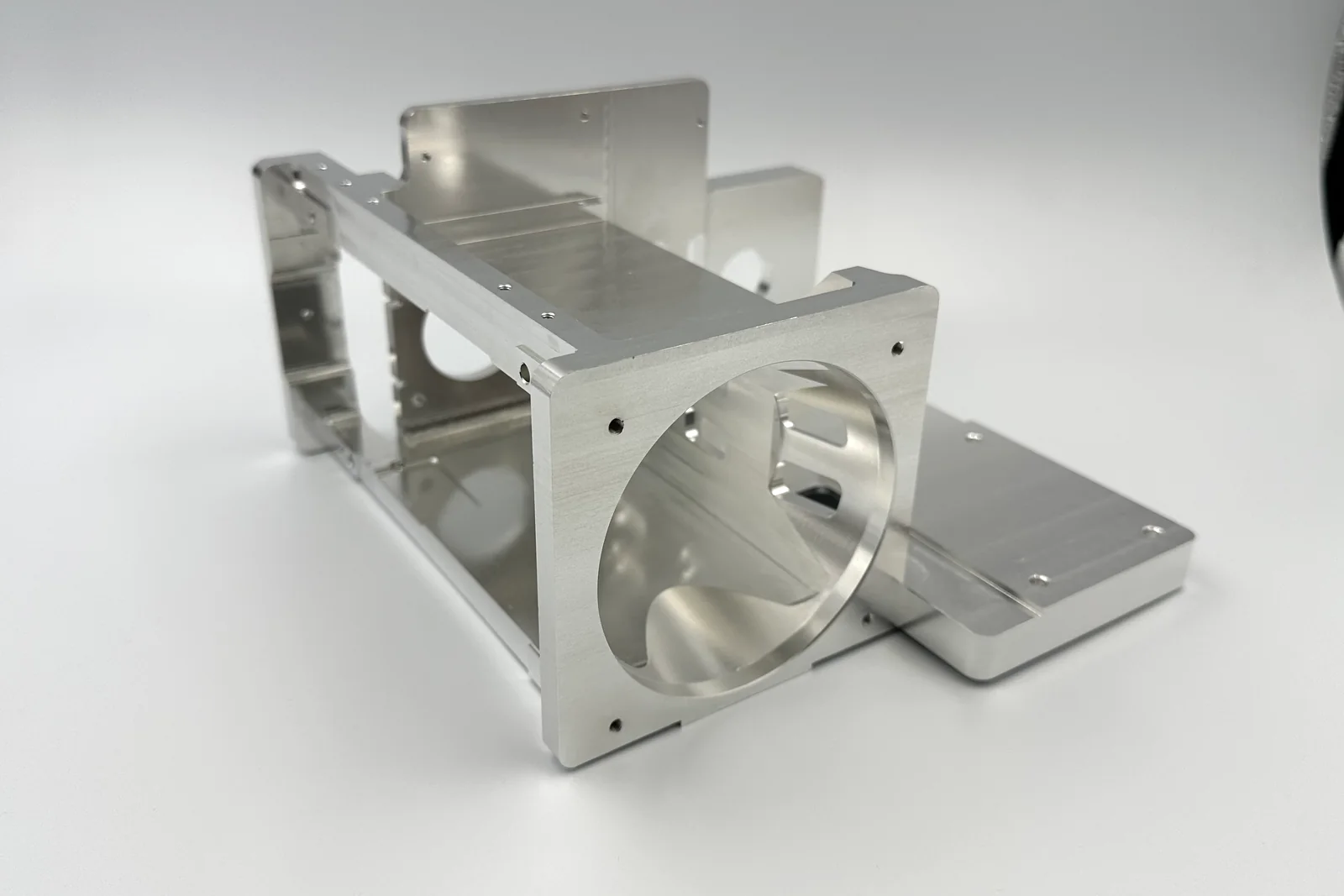
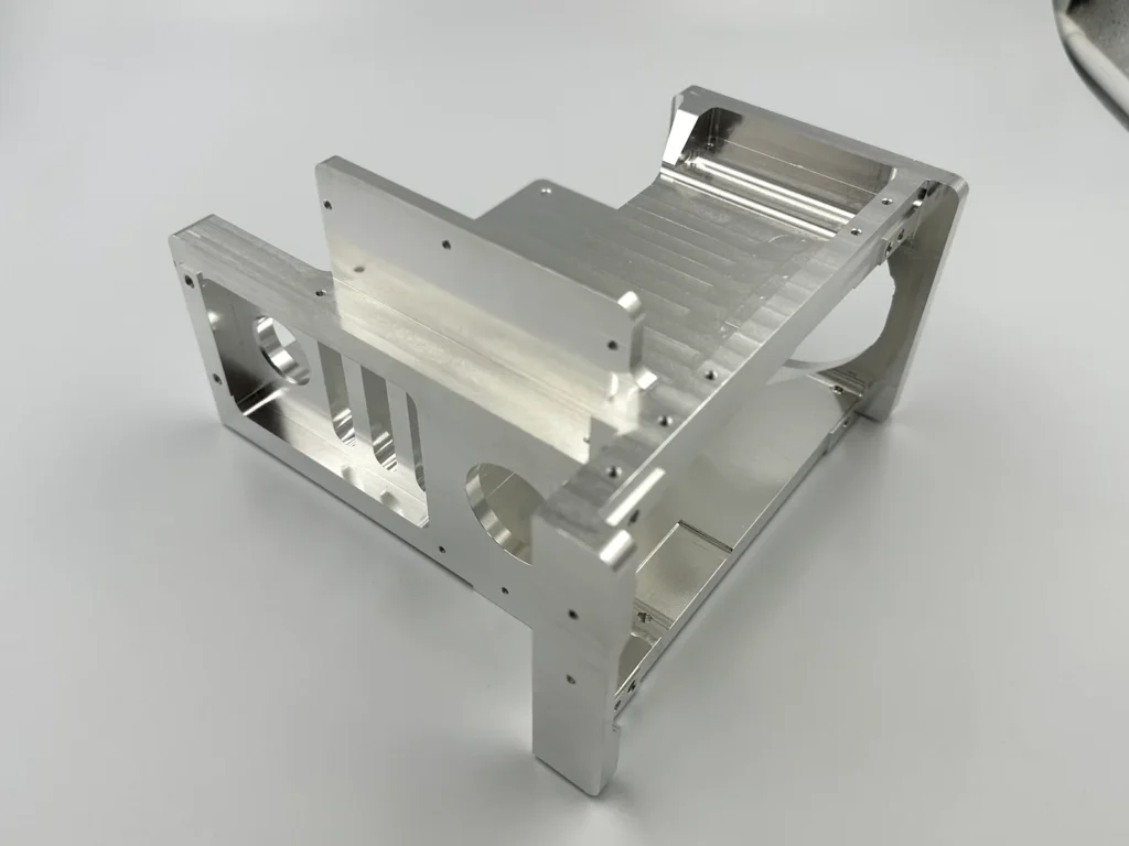
For our infrared equipment bracket, the large bore diameters, relationships between front and rear holes, mounting-face flatness, perpendicularity and mounting-hole positions were important because several components connected through the bracket. We manufactured the part as one piece from 6061-T6 stock. Its one-piece construction did not remove the need to control relationships between features machined from different directions.
When requesting a quotation, identify the mating components or provide a simplified assembly view if the full assembly is confidential. Explain where the bracket contacts the assembly and which surfaces or holes establish its position. Keep the final requirements on the approved drawing or in clearly agreed specifications rather than relying on photographs alone.
Specify bracket tolerances by function
Avoid specifying a single very tight tolerance across the entire bracket simply because one bore is critical. Identify the features that affect fit and alignment, then define their size and geometric requirements using the drawing’s chosen tolerancing standard.
The table below separates common questions that should be resolved before manufacturing. It does not assign universal tolerance values.
Flatness and perpendicularity answer different questions. Flatness concerns the form of one surface. Perpendicularity controls orientation relative to a datum. Similarly, checking a hole diameter does not establish its position relative to a mounting plane. Make those relationships explicit where the assembly requires them.
There is no single correct tolerance for every machined aluminum bracket. Feature size, mating fit, geometry, finishing and the inspection method all affect the manufacturing review. If a requirement is unclear, resolve it before programming rather than assuming that a general tolerance covers every assembly relationship.
For bore-specific decisions, see our guide to CNC hole tolerances and drilling reaming and boring.
Plan machining around access and locating references
The number of machine axes is only part of the process plan. The supplier also needs to decide how to hold the bracket, which features to finish together and how to locate it again when a clamped surface becomes accessible.
Separate rough machining from the later precision operations
For the 100-piece infrared bracket batch, we first used three-axis rough machining. We then released the workpieces from their clamps and left them to rest before the later machining operations. This part did not receive a heat treatment for stress relief.
That sequence should not be described as complete removal of residual stress. For a new bracket, discuss the roughing sequence and how dimensional stability will be assessed rather than assuming a rest period guarantees a particular result. The necessary sequence depends on the stock, the amount and distribution of removed material, and the remaining geometry.
Account for the face used to hold the part
We subsequently used five-axis machining for the accessible faces. In this setup, the face used for clamping still required a separate operation. We flipped and reclamped the bracket to machine that face, using precision holes and a machined plane as locating references.
This is a setup-specific limitation, not a rule that a five-axis machine can only machine five faces. Tool access, workholding and the part geometry determine what can be completed without reclamping. A buyer should ask which critical features remain connected through the same reference system after the part is moved.
Locating holes and planes used in manufacturing also need to be distinguished from the formal datums on the drawing. The setup must support the specified relationships; choosing a convenient fixture surface does not change the customer’s acceptance requirements. Our guide to datum transfer across multiple CNC setups discusses this issue in more detail.
Review bracket geometry before trying to reduce machining cost
For a custom machined aluminum bracket, cost depends on more than its overall dimensions. The quotation also reflects access to features, material removal, setup changes, specified tolerances, finishing and inspection. A simple-looking opening may be costly if it requires a difficult tool approach or tightly controlled relationships to another face.
Useful questions during a manufacturability review include whether internal corners can accept a larger radius, whether an opening needs its specified depth, and whether a nonfunctional surface needs the same finish as a mounting interface. These are review questions, not permission to change the design.
On a bracket connecting several components, removing a rib, opening a pocket or changing a mounting face may affect stiffness, clearance or assembly. The customer should approve any proposed geometry or tolerance change. A machining supplier should not simplify an interface merely because it is easier to cut.
Ask suppliers to quote against the same drawing revision, quantity, finish and inspection scope. Otherwise, a lower price may reflect a different requirement rather than a more efficient process. Our CNC machining cost guide covers the wider quotation factors.
Define the anodized condition before machining
For anodized aluminum brackets, state whether dimensional acceptance applies before or after anodizing. Also specify the treatment requirements and any surfaces that must remain uncoated. A silver appearance alone is not enough to define the finish or its dimensional effect.
Anodizing changes dimensions because the oxide layer forms partly into and partly beyond the original aluminum surface. Pretreatment can also affect the net change. The Aluminum Anodizers Council technical FAQ explains that process conditions and alloy affect this behavior and recommends discussing dimensional requirements with the anodizer.
How the infrared bracket batch was finished
For this bracket, we retained the machined surface texture and applied natural anodizing. We did not add cosmetic sanding or bead blasting because the process priority was to protect the specified mounting geometry from additional surface alteration.
We machined the dimensions to the drawing requirements before anodizing without a dedicated dimensional compensation offset. The parts were anodized together, and we did not perform corrective CNC machining afterward. Dimensions were checked before and after anodizing, with acceptance based on the final anodized condition.
This describes the route used for this batch, not a general recommendation to omit anodizing allowance. For another bracket, tighter fits, a different coating specification or another finishing process may require a different machining target or an approved masking plan. Those decisions should be resolved before production.
The important question is whether the complete machining and finishing route can meet the drawing in the required final condition. Do not assume that an acceptable pre-anodizing measurement automatically establishes final conformity. See our guide to anodizing and dimensional allowance for CNC parts for the finishing considerations.
Inspect the features that control bracket assembly
Match the inspection method to the requirement. A photograph can show the part and measurement setup, but it cannot establish a bore tolerance, flatness result or positional relationship. Those conclusions require inspection against the approved drawing.
For the infrared equipment bracket, we used pin gauges for small holes, a coordinate measuring machine for large bore diameters, thread gauges for threads, and CMM measurements for the specified geometric tolerances. We checked dimensions both before and after anodizing.
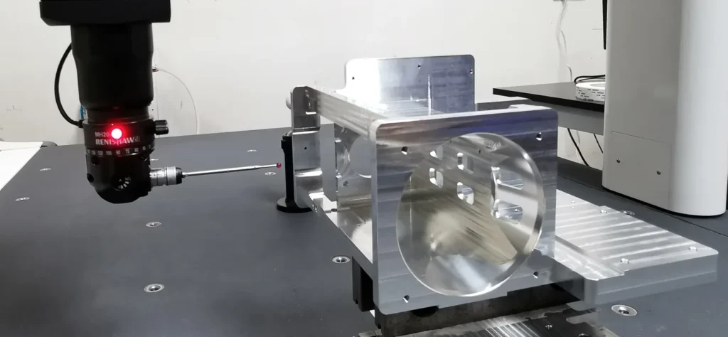
A pin gauge check addresses hole acceptance within the chosen gauge method; it does not establish the hole’s position relative to the mounting face. Thread gauges assess the specified thread acceptance and do not replace checks of the thread’s location where that is controlled. CMM inspection must likewise evaluate the features and references required by the drawing, rather than treating every measured diameter as proof of assembly alignment.
Agree on sampling and final acceptance
The 100-piece batch followed an inspection sampling plan, with different sampling proportions for ordinary and important tolerances. The sampled inspection results met the drawing requirements, and the batch required no rework or remanufacture.
These results should not be interpreted as a claim that every feature on every part was measured. For a new order, agree on the sampling scope, any features requiring full inspection, the acceptance condition and the records to be supplied. If a customer requires additional checks, include them in the manufacturing and quotation review.
Where final acceptance applies after anodizing, specify that condition in the inspection plan. Pre-finish readings remain useful process information, but the finished-state requirements govern acceptance. Our CNC machining inspection guide explains how to connect drawing requirements with inspection planning.
What to send for a custom aluminum bracket quotation
Send enough information for the supplier to review the interfaces and the complete process, not just the external shape. A useful request includes:
- The current 3D model and 2D drawing, with matching revision information.
- The material grade and temper, such as 6061-T6 where specified by the design.
- The quantity and any planned repeat-order quantities.
- Critical bore sizes, mounting-hole positions and geometric requirements with the applicable datums.
- A description or simplified view of the mating components and important contact surfaces.
- The surface treatment, cosmetic requirements and whether dimensions apply after finishing.
- The required sampling or full-inspection scope and inspection records.
If there is a conflict between the model, drawing and a separate finishing note, resolve it before ordering. Avoid relying on a verbal understanding that a surface is “important” when the supplier needs a measurable acceptance requirement.
SAMSHION provides CNC machining services for custom components. Send your bracket drawing and requirements for a quotation so we can review the machining route, feature relationships and finishing requirements together.
Frequently asked questions
Does every aluminum bracket need five axis machining
No. The choice depends on geometry, tool access, workholding and the relationships that must be controlled. A simpler bracket may be suitable for three-axis machining. In our infrared bracket batch, we combined three-axis roughing with later five-axis machining and a flipped setup for the clamping face.
Can a bore be the correct size but still cause an assembly problem
Yes. Diameter and position are different requirements. A bore can meet its size limits while its axis has the wrong relationship to another hole or mounting face. Define and inspect the relevant geometric relationships on the drawing.
Should all bracket dimensions have the same tight tolerance
Usually the drawing should distinguish functional interfaces from clearance or noncritical geometry. The design requirements determine the tolerances. Do not tighten every dimension by default or relax a functional requirement simply to reduce machining time.
Must aluminum brackets be machined again after anodizing
No. The appropriate route depends on the final requirements. Our bracket batch was accepted in the anodized condition without post-anodizing machining. Other parts may require an approved allowance, masking or a different sequence. These options need review before production rather than being treated as interchangeable fixes afterward.
Does sampling mean every bracket is measured on a CMM
No. Sampling defines which parts and features are checked under the inspection plan. It is different from measuring every feature on every part. Specify any full-inspection requirements before ordering and match the measurement method to each requirement.