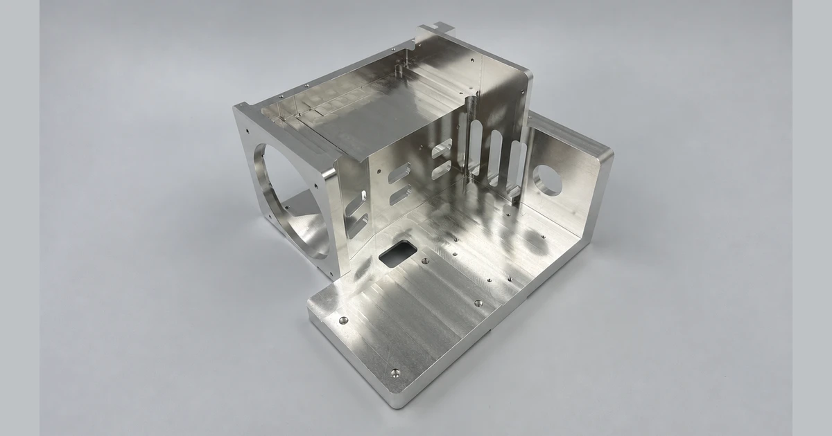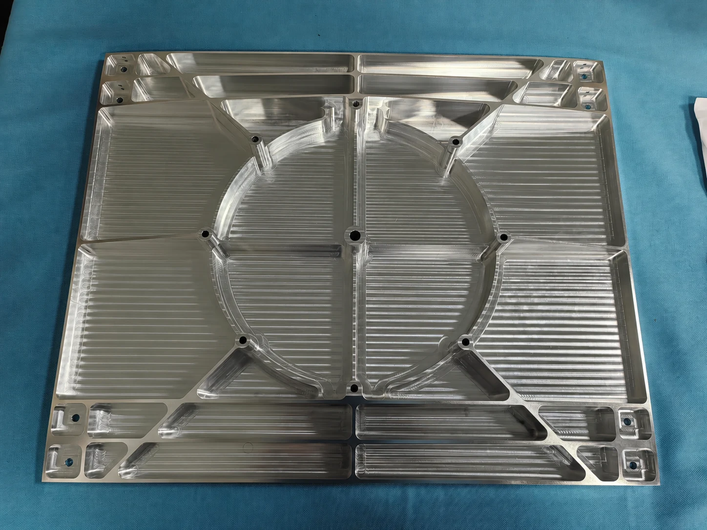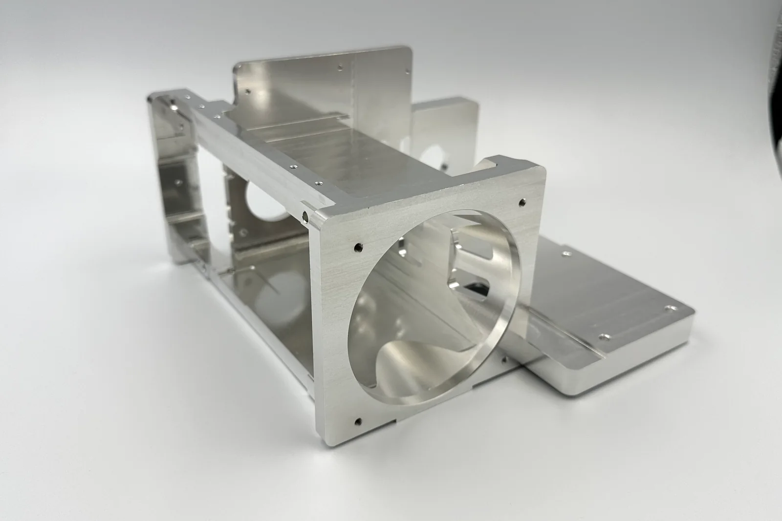
GD&T can make a CNC drawing easier to manufacture when it clearly describes how the part functions. It can also make a quotation uncertain when datum references are missing, controls conflict or every surface receives a tight profile requirement.
The supplier does not need less information. The supplier needs the right information: a stable datum reference frame, functional tolerance zones, basic dimensions and an inspection scope that can be executed on the actual part.
Scope, Search Intent and Technical Boundary
This article explains how GD&T affects quotation, setup and inspection scope. It complements rather than replaces a general explanation of GD&T symbols. For broader geometry and specification guidance, use the design for manufacturability guide alongside this feature-level discussion.
Apply the guidance to quotation and first-article planning for GD&T for CNC machining; do not treat illustrative values as guaranteed tolerances.
Key Takeaways
- Choose datums from functional and stable part interfaces.
- Use position to control feature location within a datum reference frame.
- Use profile where surface form and location must be controlled together.
- Avoid duplicate plus/minus dimensions that conflict with geometric controls.
- State the applicable drawing standard and required inspection evidence.
Why Datums Matter Before the First Toolpath
Datums establish the coordinate system used to orient dimensions and geometric tolerances. A primary datum should generally be stable enough to support repeatable setup and inspection. A tiny flexible tab may exist in CAD but make a poor manufacturing reference. The drawing should identify the governing standard; for ASME-based drawings, use ASME Y14.5 Dimensioning and Tolerancing as the authoritative reference rather than relying on informal interpretations.
The datum sequence should reflect how the part locates in assembly. Manufacturing may use temporary process datums, but the final features still need to relate to the functional drawing datums. For the corresponding manufacturing decision and capability context, consult SAMSHION’s CNC fixturing and setup guide.
Position Controls Location More Clearly
Position is commonly applied to holes, pins and other features of size. Basic dimensions define the theoretically exact location, while the feature control frame defines the allowable tolerance zone relative to datums. For the corresponding manufacturing decision and capability context, consult SAMSHION’s CNC production machining.
Do not add plus/minus location dimensions that create a second competing requirement. Clarify material-condition modifiers when they are functionally intended.
Profile for Complex Surfaces
Profile can control the form, orientation and location of a surface within a defined zone. It is useful for cast or machined contours, sealing paths and complex surfaces, but it should be applied with a clear datum structure and coverage.
A profile callout across the entire part may create expensive inspection when only a local interface is functional. Use ‘all around’ or ‘all over’ only when that is truly the design intent.
Runout, Flatness and Perpendicularity
Runout relates rotating surfaces to a datum axis and is often relevant to shafts, bearing seats and sealing diameters. Flatness is a form control and does not require a datum. Perpendicularity controls orientation relative to a datum. For the corresponding manufacturing decision and capability context, consult SAMSHION’s CNC turning services.
Selecting the correct control avoids stacked requirements and makes inspection more direct.
Connect GD&T to the Inspection Plan
A feature control frame is useful only when the measurement method can realize the datum setup and access the controlled surface. CMM, vision, scanning, functional gauges and manual methods have different strengths.
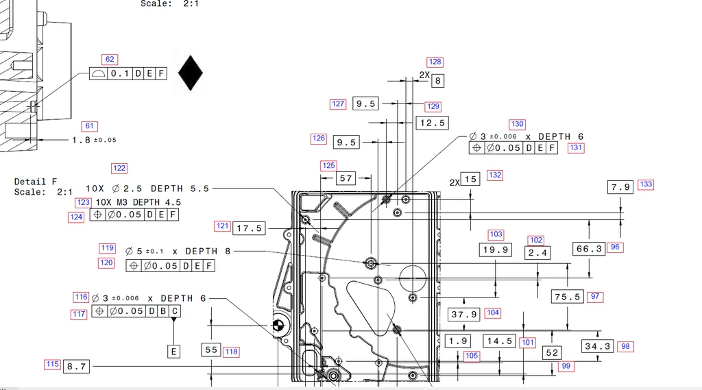
For quotation, identify whether a full first-article report, selected critical dimensions or a certificate of conformance is required.
Drawing Review Checklist
- Applicable GD&T standard and drawing revision
- Stable primary, secondary and tertiary datums
- Basic dimensions for controlled feature locations
- No conflicting duplicate dimensions
- Inspection report scope and customer-supplied gauges
Engineering Variables to Confirm Before Quotation
Datum feature stability and accessibility
For GD&T for CNC machining, datum feature stability and accessibility requires an explicit engineering decision. Use this requirement to frame the first technical review. Ask which function depends on it, which datum or material state establishes it, and at what production stage it will be accepted. The decision can move a feature from a routine check to a controlled first-article characteristic. Keep the decision with the job record, because a verbal answer cannot control repeat work.
Material condition modifiers and virtual condition
For GD&T for CNC machining, material condition modifiers and virtual condition requires an explicit engineering decision. Treat this as an RFQ input, not a shop-floor surprise. Ask which function depends on it, which datum or material state establishes it, and at what production stage it will be accepted. Its interpretation changes datum selection, setup count and verification effort. Tie any relaxation to the actual function rather than to a generic shop capability statement.
Position versus coordinate tolerancing
For GD&T for CNC machining, position versus coordinate tolerancing requires an explicit engineering decision. Use this requirement to frame the first technical review. Ask which function depends on it, which datum or material state establishes it, and at what production stage it will be accepted. The result governs how much process evidence is needed to support the quotation. Quote alternatives separately when more than one technically credible interpretation exists.
Profile applied to a surface or all-around boundary
For GD&T for CNC machining, profile applied to a surface or all-around boundary requires an explicit engineering decision. Make the functional intent visible before tooling is selected. Ask which function depends on it, which datum or material state establishes it, and at what production stage it will be accepted. It may determine whether a flexible prototype route remains suitable for repeat production. A written assumption lets the buyer compare suppliers on an equivalent technical basis.
Simultaneous and separate requirements
For GD&T for CNC machining, simultaneous and separate requirements requires an explicit engineering decision. Resolve this point while the process route is still flexible. Ask which function depends on it, which datum or material state establishes it, and at what production stage it will be accepted. A different answer may require different stock, clamping pressure or inspection equipment. Record the agreed interpretation beside the revision so later orders do not reopen the same ambiguity.
Inspection alignment that recreates the datum reference frame
For GD&T for CNC machining, inspection alignment that recreates the datum reference frame requires an explicit engineering decision. Confirm the delivered-state requirement before estimating cycle time. Ask which function depends on it, which datum or material state establishes it, and at what production stage it will be accepted. A different answer may require different stock, clamping pressure or inspection equipment. The review is complete only when production and inspection use the same definition.
Failure Modes and Root-Cause Diagnosis
A cosmetic surface is selected as the primary datum despite poor repeatability
A characteristic failure for GD&T for CNC machining occurs when a cosmetic surface is selected as the primary datum despite poor repeatability. The observation is evidence, not yet a root cause. Evaluate material behavior, support, cutter condition, programmed sequence and the measurement alignment as separate hypotheses. Use a controlled trial that changes one suspected mechanism while holding the remaining variables constant. Run the corrected first article through the same final-state acceptance route as production parts.
A position tolerance is quoted without understanding its datum order
A characteristic failure for GD&T for CNC machining occurs when a position tolerance is quoted without understanding its datum order. The observation is evidence, not yet a root cause. Evaluate material behavior, support, cutter condition, programmed sequence and the measurement alignment as separate hypotheses. Compare the blank, clamped part, released part and finished part to locate the stage where the error appears. Update the setup sheet and inspection plan so the fix survives the next batch.
Profile controls more surface than the designer intended
A characteristic failure for GD&T for CNC machining occurs when profile controls more surface than the designer intended. The observation is evidence, not yet a root cause. Evaluate material behavior, support, cutter condition, programmed sequence and the measurement alignment as separate hypotheses. Preserve the failed part condition long enough to distinguish cutting evidence from handling or finishing damage. Update the setup sheet and inspection plan so the fix survives the next batch.
Supplier and customer align the same part differently and report conflicting results
A characteristic failure for GD&T for CNC machining occurs when supplier and customer align the same part differently and report conflicting results. The observation is evidence, not yet a root cause. Evaluate material behavior, support, cutter condition, programmed sequence and the measurement alignment as separate hypotheses. Use a controlled trial that changes one suspected mechanism while holding the remaining variables constant. Update the setup sheet and inspection plan so the fix survives the next batch.
Process Controls for a Repeatable Result
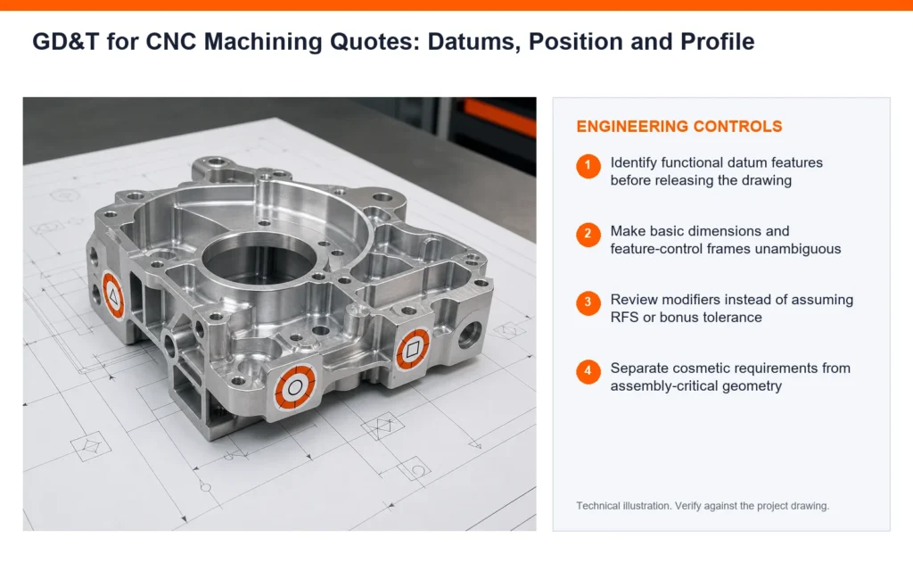
Identify functional datum features before releasing the drawing
A process plan for GD&T for CNC machining can control this risk by choosing to identify functional datum features before releasing the drawing. The action is useful only when it targets a named source of variation. Before release, consider access, local stiffness, heat flow and the acceptance condition of neighboring features. Use a short prototype trial first; formalize fixture, sampling and tool-life rules for repeat orders. Retain enough evidence to distinguish setup drift from material or tool variation.
Make basic dimensions and feature-control frames unambiguous
A process plan for GD&T for CNC machining can control this risk by choosing to make basic dimensions and feature-control frames unambiguous. The action is useful only when it targets a named source of variation. Before release, consider access, local stiffness, heat flow and the acceptance condition of neighboring features. Use a short prototype trial first; formalize fixture, sampling and tool-life rules for repeat orders. Repeat production should not depend on an operator remembering an undocumented exception. The applicable production route and process controls are outlined in SAMSHION’s CNC machining services.
Review modifiers instead of assuming RFS or bonus tolerance
A process plan for GD&T for CNC machining can control this risk by choosing to review modifiers instead of assuming RFS or bonus tolerance. The action is useful only when it targets a named source of variation. Before release, consider access, local stiffness, heat flow and the acceptance condition of neighboring features. Pair the control with a measurable limit rather than a general workmanship instruction. Retain enough evidence to distinguish setup drift from material or tool variation.
Separate cosmetic requirements from assembly-critical geometry
A process plan for GD&T for CNC machining can control this risk by choosing to separate cosmetic requirements from assembly-critical geometry. The action is useful only when it targets a named source of variation. Before release, consider access, local stiffness, heat flow and the acceptance condition of neighboring features. Pair the control with a measurable limit rather than a general workmanship instruction. Escalate a trend before it crosses the acceptance limit.
Plan how the datum frame will be simulated during machining and inspection
A process plan for GD&T for CNC machining can control this risk by choosing to plan how the datum frame will be simulated during machining and inspection. The action is useful only when it targets a named source of variation. Before release, consider access, local stiffness, heat flow and the acceptance condition of neighboring features. Define the owner, frequency and record produced by the control. If it changes a controlled requirement, customer approval comes before production release.
Resolve unclear callouts before price and lead time are fixed
A process plan for GD&T for CNC machining can control this risk by choosing to resolve unclear callouts before price and lead time are fixed. The action is useful only when it targets a named source of variation. Before release, consider access, local stiffness, heat flow and the acceptance condition of neighboring features. Assign an operator check at the operation where the variable can still be corrected. The inspector must evaluate the same condition the operator is controlling.
Inspection Strategy and Acceptance Evidence
Datum feature simulator and alignment method
Inspection of GD&T for CNC machining should explicitly address datum feature simulator and alignment method. First define the characteristic, datum reference and part condition represented by the result. Sample the locations and depths where process behavior can genuinely change. Retain traceability to the part revision and the production stage at which acceptance occurred.
Position result at the correct material condition
Inspection of GD&T for CNC machining should explicitly address position result at the correct material condition. First define the characteristic, datum reference and part condition represented by the result. Build the datum alignment exactly as defined on the controlled drawing. Keep the measurement program and fixture revision with the inspection record.
Profile evaluation zone and filtering method
Inspection of GD&T for CNC machining should explicitly address profile evaluation zone and filtering method. First define the characteristic, datum reference and part condition represented by the result. Measure in the delivered condition whenever coating, heat treatment or release affects the result. When results disagree, compare alignment, force, temperature and feature definition before averaging values.
Cross-setup relationships
Inspection of GD&T for CNC machining should explicitly address cross-setup relationships. First define the characteristic, datum reference and part condition represented by the result. Build the datum alignment exactly as defined on the controlled drawing. A decimal-rich output is not credible if the instrument cannot resolve the tolerance. The available verification and reporting workflow is summarized in SAMSHION’s quality assurance.
Report format that preserves nominal, tolerance and actual values
Inspection of GD&T for CNC machining should explicitly address report format that preserves nominal, tolerance and actual values. First define the characteristic, datum reference and part condition represented by the result. Select contact geometry and measuring force that will not distort or bridge the feature. Keep the measurement program and fixture revision with the inspection record.
Cost, Lead Time and Quotation Transparency
Number of controlled features
In a quotation for GD&T for CNC machining, number of controlled features can influence both lead time and total manufacturing cost. A prototype route may be economical once but unsuitable for a repeating order. Tie any cost-saving proposal to a controlled drawing revision.
Custom fixtures for datum simulation
In a quotation for GD&T for CNC machining, custom fixtures for datum simulation can influence both lead time and total manufacturing cost. Dedicated support or gauging may raise initial cost while lowering variation across a batch. Tie any cost-saving proposal to a controlled drawing revision.
CMM programming and reporting
In a quotation for GD&T for CNC machining, CMM programming and reporting can influence both lead time and total manufacturing cost. Dedicated support or gauging may raise initial cost while lowering variation across a batch. Offer a DFM alternative only when it preserves assembly, sealing, load or appearance.
Ambiguity requiring engineering review
In a quotation for GD&T for CNC machining, ambiguity requiring engineering review can influence both lead time and total manufacturing cost. Its effect depends on whether the requirement applies to every part or only first-article evidence. Do not reduce price by silently omitting the requested acceptance evidence. The wider effect of setup, tolerance and documentation choices is explained in the CNC machining cost guide.
A Practical Engineering Review Sequence
Start with the function protected by datum feature stability and accessibility. Mark the related datums, interfaces and delivered-state requirements on the controlled drawing. The manufacturing review can then choose stock, setups and cutting access around that function instead of treating every dimension as equally critical.
Walk through the likely failure mechanism represented by this project: a cosmetic surface is selected as the primary datum despite poor repeatability. Decide which evidence can reveal the problem earliest and which operation can still correct it. This ordering avoids discovering a predictable condition only after finishing or final inspection.
Use the first article to validate the proposed control, including the instruction to identify functional datum features before releasing the drawing. The approval part must represent the intended material, fixture, program, secondary operations and measurement alignment. Feed the result back into the process record before releasing the balance of the order.
RFQ and DFM Checklist
- Native 3D CAD model plus a controlled 2D drawing for tolerances and notes
- Exact material grade, condition, stock preference and certification requirement
- Functional datums, mating components and genuinely critical characteristics
- Quantity, prototype or production intent, and expected repeat-order status
- Surface finish, coating, heat treatment, cleaning and marking requirements
- Inspection report, certificate, gauge or sampling requirements
- Any approved alternative geometry or process constraints
Additional Engineering Review Notes
An additional risk review should connect the drawing statement to the evidence available at final acceptance. For GD&T for CNC machining, examine datum feature stability and accessibility and ask how it could contribute to a condition in which a position tolerance is quoted without understanding its datum order. One candidate action is to review modifiers instead of assuming RFS or bonus tolerance; however, its value must be demonstrated through cross-setup relationships. Preserve enough traceability to connect the observation to material lot, setup and program revision. Also consider the commercial effect of number of controlled features, because a technically sound route must be quoted with transparent assumptions. Remove process steps that add handling but do not reduce the targeted source of variation.
For repeat orders, convert the first-article lesson into a revision-controlled production instruction. For GD&T for CNC machining, examine material condition modifiers and virtual condition and ask how it could contribute to a condition in which profile controls more surface than the designer intended. One candidate action is to separate cosmetic requirements from assembly-critical geometry; however, its value must be demonstrated through report format that preserves nominal, tolerance and actual values. Record the part state and operation where the observation first becomes visible. Also consider the commercial effect of custom fixtures for datum simulation, because a technically sound route must be quoted with transparent assumptions. Keep the approved method connected to the fixture, program and inspection revision.
A useful design-review exercise is to trace one requirement through the complete production route. For GD&T for CNC machining, examine position versus coordinate tolerancing and ask how it could contribute to a condition in which supplier and customer align the same part differently and report conflicting results. One candidate action is to plan how the datum frame will be simulated during machining and inspection; however, its value must be demonstrated through datum feature simulator and alignment method. Retain a marked image or inspection trace so the team is discussing the same location. Also consider the commercial effect of CMM programming and reporting, because a technically sound route must be quoted with transparent assumptions. Escalate a trend at the warning limit instead of waiting for a rejected final result.
Frequently Asked Questions
Does GD&T automatically make a part more expensive?
Not necessarily. Clear functional GD&T can reduce ambiguity and prevent unnecessary tight coordinate tolerances. Treat this as planning guidance and document any project assumption in the quotation.
Can a supplier change the datums?
Process datums may differ, but drawing requirements should not be changed without customer approval. Final acceptance depends on the stated datum, delivered state and inspection approach.
Is flatness referenced to a datum?
Flatness is a form control and does not use a datum reference. Supplier and customer should agree the feature definition before production begins.
Should every dimension be on a CMM report?
Only if that reporting scope is required. Inspection should be agreed according to risk and contract requirements. Treat this as planning guidance and document any project assumption in the quotation.
Get an Engineering Review
Send the model, controlled drawing and report requirements for a GD&T and manufacturability review before production. When the model and drawing are ready, use upload CAD and drawings and include the material, quantity, finish and inspection requirements.
For a review of GD&T for CNC machining, send the native CAD model, controlled drawing, material specification, quantity, finishing route and required acceptance records. SAMSHION’s engineering team can return project-specific DFM questions and documented quotation assumptions before production begins.