Introduction
Threads look simple on a drawing, yet they combine geometry, material behavior, tool access, chip control and inspection in one feature. A thread can appear visually acceptable and still fail assembly because its pitch diameter, lead, depth, alignment or entrance condition is wrong. The most reliable approach is to define the functional requirement first and let the manufacturing plan follow it.
This guide explains how to specify and manufacture CNC-machined threads without relying on vague notes such as “tap as required.” It covers internal and external threads, tapping, thread milling, blind-hole design, inserts and practical inspection. For a broader review of subtractive manufacturing, begin with our CNC machining services page.
What Information Belongs in a Thread Callout?
A supplier should not have to infer the thread system or acceptance requirement. The drawing or model-based definition should identify the nominal size, pitch or threads per inch, internal or external form, tolerance class and required threaded depth. Add the applicable standard when it matters to the product or customer.
For Unified inch threads, ASME B1.1 specifies thread forms, series, classes, allowances, tolerances and designations. ISO metric general-purpose thread tolerances are organized by ISO 965. These standards define the thread system; they do not replace a functional drawing that identifies location, orientation, depth and related datums.
Define Threaded Depth Separately From Drill Depth
In a blind hole, drill depth is normally greater than full thread depth. Space is needed for the drill point, chip accumulation, tap lead or thread-mill approach and a safe clearance before the bottom. Calling out only the overall hole depth can leave the machinist unsure how much complete thread is actually required.
Specify the minimum full-form thread engagement needed by the assembly. If the hole must stop close to an internal wall, identify that constraint early so the manufacturing engineer can evaluate a bottoming tap, thread mill, alternate fastener or design change.
Show Which Face Controls the Thread Axis
A threaded hole often locates a cover, bracket or connector. In that case, thread position and axis orientation may matter more than cosmetic appearance. Establish functional datums and apply tolerances that reflect assembly. Our design for manufacturability guide explains why manufacturing requirements should follow function rather than arbitrary precision.
Tapping, Thread Milling or Single-Point Threading?
Method | Best suited to | Main strengths | Main constraints |
Cutting tap | Repeated standard internal threads | Fast cycle and common tooling | Chip control, torque and broken-tool risk require attention |
Form tap | Ductile materials and suitable pilot holes | No chips and strong formed surface | Material and lubrication dependent; not suitable for every alloy or specification |
Thread mill | Valuable parts, larger holes, difficult materials and adjustable size | Good chip control; one tool can cover several diameters of the same pitch | Requires helical interpolation and usually more cycle time |
Single-point turning | External or internal threads on rotational parts | Flexible profiles and concentricity in the turning setup | Primarily suited to lathe-accessible geometry |
When Tapping Is Efficient
Tapping is often the fastest method for common internal threads in production. A tap cuts or forms the complete thread as it advances at a synchronized feed. The pilot-hole diameter, tap geometry, coolant delivery and machine synchronization all affect torque and thread quality.
Through holes usually offer easier chip evacuation than blind holes. Blind-hole tapping requires a deliberate chip strategy and sufficient bottom clearance. A broken tap in a nearly finished component can be costly, so high-value parts may justify a slower but more recoverable method.
When Thread Milling Reduces Risk
A thread mill follows a helical toolpath and cuts the thread progressively. Tool diameter is smaller than the finished thread, so a broken tool is often easier to remove than a broken tap. Radial compensation can also adjust the finished pitch diameter without changing the programmed thread pitch.
OSG notes that thread milling can be more stable than general tapping where chip management and coolant conditions are difficult. It is also useful when one pitch must be applied to different thread diameters, when the part is expensive or when a large tap would impose excessive torque. The tradeoff is additional programming and cycle time.
External Threads
External threads on turned components may be single-point cut, die cut, milled or produced by another qualified process. The selection depends on diameter, pitch, material, shoulder clearance, concentricity and volume. Review rotational features together with our CNC turning services rather than treating the thread as an isolated note.
How to Design a Reliable Tapped Hole
Provide Tool Access and Entrance Clearance
The tool must approach along the thread axis. Nearby walls, bosses and overhangs can block the spindle, holder or gauge even when the hole itself is visible. A small entrance chamfer helps start the fastener, protects the first thread and removes a sharp edge, but it should not remove needed engagement.
Avoid Unnecessary Depth
More thread depth does not automatically produce a stronger joint. Required engagement depends on the screw and parent materials, load direction, thread size, fastener grade, repeated assembly and failure mode. Excessive depth can increase drilling and threading time without improving the joint. Engineering calculations or validated design rules should determine engagement.
Place Threads Away From Fragile Edges
Threads close to a thin wall or free edge can distort during machining or tightening. The remaining material must carry installation torque and service load. If space is restricted, consider a larger boss, local rib, through-fastener, insert or alternative joint configuration. For flexible geometry, review the principles in our thin-wall CNC machining guide after it is published.
Account for Finishing
Anodizing, plating, paint and conversion coatings can change fit at the thread interface. Decide whether the threads will be masked, chased, oversized before coating or accepted after a validated coating process. Do not let the finishing supplier make this decision without the drawing requirement. Available treatments are summarized on our surface finishing services page.
Blind Holes Need a Complete Depth Stack
A useful blind-hole definition separates four zones: entrance chamfer, full-form thread, incomplete thread or tool runout, and drill-point clearance. The exact stack depends on the chosen drill and threading method, so the drawing should focus on functional thread depth while avoiding an unnecessarily tight hole-bottom requirement.
If the fastener must stop at a precise axial position, use a shoulder, spacer or controlled boss height instead of relying on the screw to bottom in the drilled hole. Bottoming a screw can create unpredictable preload and damage incomplete threads.
Threaded Inserts: When the Parent Material Is Not Enough
Threaded inserts can improve serviceability in aluminum, magnesium and some plastics, especially when a joint will be assembled repeatedly. Wire inserts, solid bushings and key-locking inserts have different installation requirements and pull-out behavior. Choose an insert system before finalizing the boss diameter and hole depth because the insert requires its own pilot hole, thread and installation access.
An insert is not an automatic repair for every damaged hole. The surrounding material, edge distance, remaining wall and load path still need review. On prototype parts, a standard insert can be practical when repeated assembly is expected. On production parts, installation control and inspection should be part of the process plan.
How Are CNC Threads Inspected?
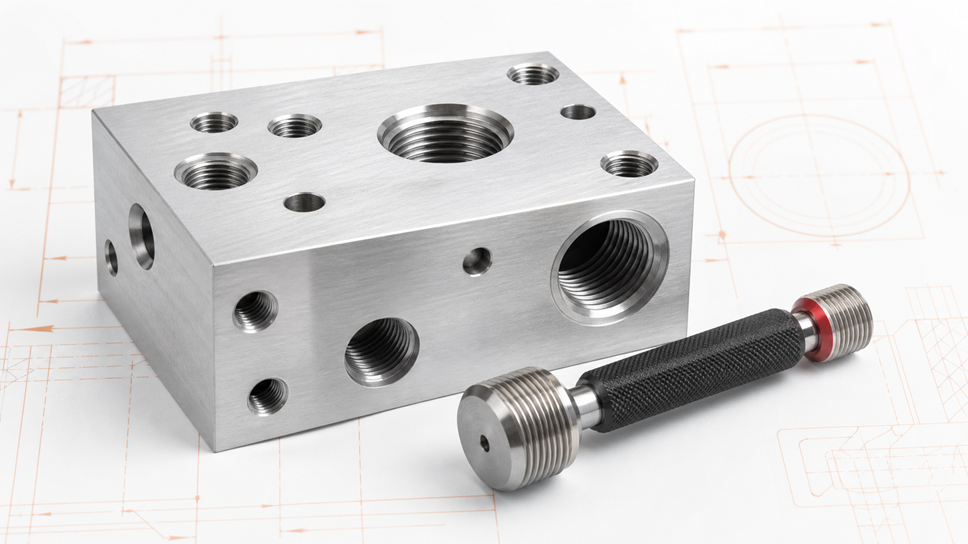
Inspection should match the requirement. A functional GO thread gauge checks whether the mating boundary can enter to the specified extent. A NO-GO gauge checks a different acceptance limit and should be used according to the applicable standard and inspection procedure. Visual inspection alone cannot establish pitch-diameter conformance.
Thread wires, thread micrometers, optical systems and coordinate measurement may support external-thread or profile evaluation, but the method must suit the characteristic. A CMM is valuable for thread location and axis relationships, yet a standard tactile routine is not a substitute for every functional thread gauge. Our CNC machining inspection guide explains how to connect drawing characteristics to gauges, CMM programs and dimensional reports.
Inspection Questions to Answer Before Production
- Is the thread standard and tolerance class identified?
- Is full thread depth measurable with the selected gauge?
- Must the thread axis relate to a datum or mating feature?
- Will the thread be inspected before or after surface finishing?
- Does the customer require a dimensional report, material certificate or first article package?
Samshion’s quality assurance and inspection systems page describes the wider control plan for machined parts.
Common Thread Failures and Corrective Actions
Symptom | Likely contributors | Corrective direction |
Gauge starts but binds | Burrs, incorrect pitch diameter, taper or coating buildup | Confirm deburring, process offset and post-finish requirement |
Shallow usable thread | Incomplete lead threads or insufficient bottom clearance | Separate full thread depth from drill depth and review tooling |
Fastener cross-threads | Poor entrance, axis error or damaged first thread | Add controlled chamfer and verify position/orientation |
Tap breaks | Excessive torque, poor chip evacuation, misalignment or unsuitable tap | Review pilot hole, tool style, coolant and thread-milling alternative |
Insert pulls out | Inadequate parent material, installation error or overload | Recalculate load path and validate boss geometry and installation |
DFM Checklist for CNC Threads
- State the complete thread designation and applicable standard.
- Separate full thread depth from total drilled depth.
- Provide straight tool and gauge access.
- Use functional tolerances and datums.
- Review edge distance and remaining wall thickness.
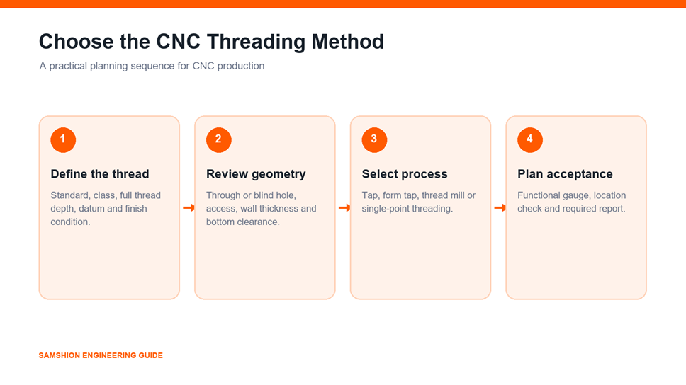
- Select tapping, thread milling or turning based on risk and volume.
- Define how finishing affects the thread.
- Identify the inspection method and documentation level.
Request a Threaded-Part Review
Upload a 3D CAD model and a 2D drawing showing thread callouts, critical datums, material, quantity and finish. Our engineers can review tool access, blind-hole depth, thread method, insert options and inspection requirements before production. Request an instant manufacturing quote.
Frequently Asked Questions
Is thread milling always better than tapping?
No. Tapping is often faster for standard repeated holes. Thread milling becomes attractive when chip evacuation, tool-breakage recovery, diameter adjustment, difficult materials or part value carry more weight than the shortest cycle.
Should a blind tapped hole be drilled only to the thread depth?
Normally no. The drill point and threading tool require additional space beyond the specified full thread. The necessary allowance depends on tooling and process planning.
Can the same thread mill cut different diameters?
Often it can cut multiple diameters that share a compatible pitch and profile, subject to tool and machine limits. The toolpath determines the finished diameter.
Do coated threads need special planning?
Yes. Coating buildup or masking can affect assembly. Define whether acceptance occurs before or after finishing and coordinate the thread allowance with the chosen treatment.
Is a CMM enough to inspect every thread?
No. A CMM can evaluate position and related geometry, but functional thread acceptance often uses specified gauges or dedicated thread-measurement methods.