Flatness controls the shape of a surface. Parallelism controls its orientation relative to a datum. A CNC machined face can be flat and still sit at the wrong angle to the mounting reference beneath it. For an assembly, that difference can determine whether a plate seats correctly, a bracket aligns, or adjoining components meet as intended.
This guide focuses on surface flatness and surface parallelism on CNC machined parts. It explains what to put on a drawing, how workholding affects the finished result, and why a visible gap under a part is not automatically its flatness error. Axis parallelism and flatness applied to a derived median plane require different interpretations and are outside this guide.
The difference between flatness and parallelism
For surface flatness, the controlled surface must fit between two parallel planes separated by the specified tolerance. Those planes are not oriented by another datum. Flatness therefore does not need a datum reference. KEYENCE illustrates this form control in its flatness measurement guide.
For surface parallelism, the tolerance zone also consists of two parallel planes, but their orientation is fixed parallel to the referenced datum plane. The measured surface must fit inside that oriented zone. The tolerance controls surface variation as well as tilt relative to the datum; it is not simply an angle between two fitted planes. See KEYENCE’s parallelism measurement explanation.
Thickness, flatness, and parallelism should be read together with the drawing’s governing standard. Size specifications may impose additional form requirements under that standard. Do not assume that a thickness tolerance alone expresses every functional requirement for two mating faces.
Roughness is a separate question. A face with fine machining marks can still be bowed or tilted. Conversely, an acceptable geometric form does not prove that its texture meets a specified Ra value. Our guide to surface roughness versus dimensional tolerance discusses this distinction in more detail.
Why a flat face can still fail parallelism
Imagine a rigid plate with a flat bottom mounting face and a flat upper face, but with the upper face inclined like a shallow wedge. Each face can satisfy its individual flatness requirement while the upper face fails parallelism to a datum established from the bottom. Making a smoother finishing pass on top does not necessarily correct that angular relationship.
Surface parallelism already limits the controlled surface’s form within its oriented zone. A separate flatness callout can be useful when the design needs a tighter form limit than the parallelism requirement. It should express a functional need rather than repeat an equivalent requirement without purpose.
Parallelism also does not specify the distance between faces. A surface can occupy an acceptable parallel orientation at the wrong height. The drawing still needs the relevant size or location requirement. For a mounting plate, ask separately whether the face is sufficiently flat, correctly oriented, and at the correct distance from the mating interface.
What to define on the drawing before requesting a quote
Start with the assembled function. Identify which face seats against another component and which face must maintain orientation to it. A datum should represent the functional reference, not merely the surface that looks easiest to probe.
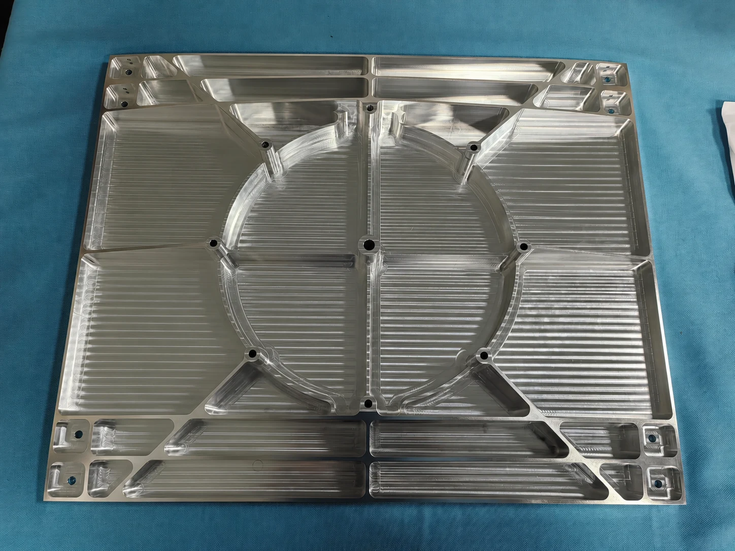
Make the extent of the controlled surface clear. A continuous mounting face, several separated pads, and selected datum targets are not interchangeable instructions. If only designated contact areas matter, define them appropriately instead of leaving the supplier to decide whether pockets, relieved areas, or separate lands belong to one requirement.
Before release, check that the drawing communicates:
- The controlled face or area and its geometric tolerance.
- The datum reference for parallelism and the applicable datum order where needed.
- The related thickness or location dimension and its tolerance.
- The drawing standard, units, revision, and any special inspection conditions.
- Whether acceptance applies before or after a specified coating or other finishing operation.
Do not assign the same tight tolerance to every face by default. A functional mounting interface and a relieved, noncontact surface may need very different controls. Clarifying that distinction helps the supplier plan machining and inspection without weakening the assembly requirement. Our GD&T guide for CNC machining quotes covers the wider drawing review.
Support conditions are part of the measurement
At SAMSHION, we measure these parts naturally placed and supported rather than forcing them flat to obtain a reading. The actual support arrangement depends on the part structure. This practice must still be checked against the customer’s drawing and agreed acceptance conditions.
A thin plate or flexible component can change shape when its support points, orientation, or restraint change. If acceptance is specified in a restrained condition, the fixture and restraint need to be defined. If it is specified in a free state, an unspecified clamp cannot be used to make the part pass. KEYENCE’s guide to non-rigid parts explains why free-state conditions, including gravity direction, matter.
For a repeatable check, document how the part rests, where it is supported, and whether any restraint is applied. Clean contact surfaces and remove loose contamination before inspection. For parallelism, establish the datum from the specified datum feature using an appropriate method; simply laying a part on a granite table does not automatically establish the drawing datum correctly.
Why a feeler gauge gap is not the flatness result
When a location lifts away from a measuring platform, we can check the gap between that location and the platform and tell the customer the observed lift-off amount. This is useful information about how the part sits in that particular condition. It is different from evaluating the entire controlled surface against a flatness tolerance zone.
The photograph shows a CNC machined ABS component and a feeler blade marked 0.70 mm. That marking identifies the blade’s nominal thickness. The photograph alone does not establish the maximum gap, a complete flatness result, or whether the component meets its drawing.
A local gap depends on where the part touches the platform, the selected measurement position, and the contact conditions. Pushing a blade in forcefully can also change how a flexible part sits. A top-view photograph does not show all of these conditions. It should therefore accompany a clearly named local gap observation rather than be presented as a complete geometric inspection report.
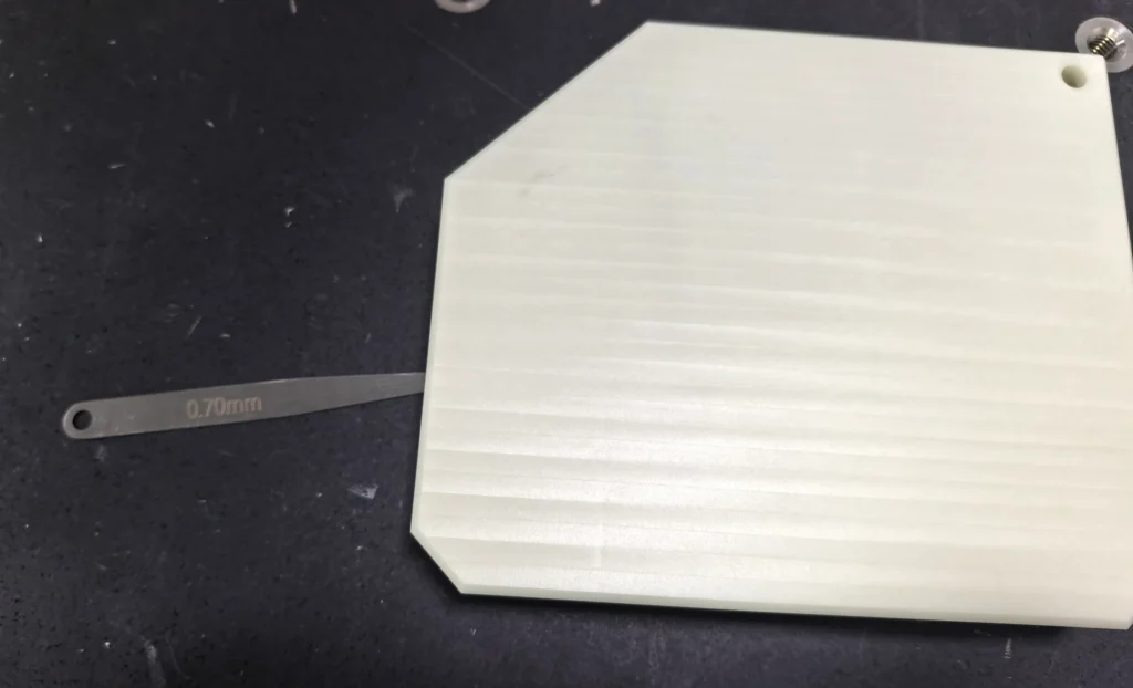
Keep the two records separate when communicating with a customer: the gap observation describes a location and setup; the CMM evaluation addresses the specified geometric characteristic. Neither should be silently relabeled as the other. The ABS example illustrates the measurement distinction, not a universal acceptance limit for CNC plastic parts.
How CNC process planning addresses the requirements
Our commonly used approaches include selecting suitable support and workholding, separating roughing from finishing, and flipping the part for additional machining. The combination depends on the geometry and on which surfaces must maintain a relationship.
Support the part without machining it in a forced shape
Clamping must hold the workpiece securely, but it also affects the shape being machined. If a flexible section is pulled against a fixture, a face may look correct while clamped and change when released. The process review therefore needs to consider both the cutting condition and the supported inspection condition.
Support locations should suit the cutting forces and the stiffness of the structure. A large unsupported flange and a compact block should not automatically use the same arrangement. Additional support is useful only when it stabilizes the workpiece without imposing an unintended shape.
Separate roughing from the final geometric work
Roughing removes the bulk of the material. Separating that stage from finishing gives the process an opportunity to reassess the part and its support before producing the critical faces. The finishing plan should account for what remains after roughing rather than assume that the initial setup stays suitable throughout.
The stock allowance, sequence, and need for intermediate checks depend on the actual material and structure. A fixed allowance or resting time is not a general recipe for flatness. These choices need to be established for the job; they are not dimensions to invent in a drawing review.
Preserve the reference when flipping the part
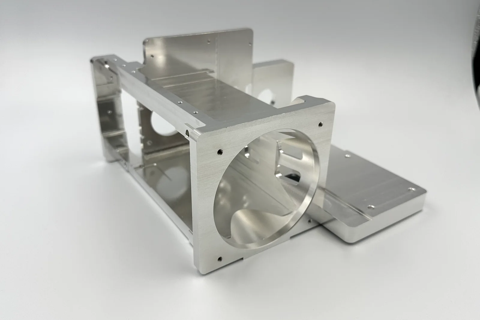
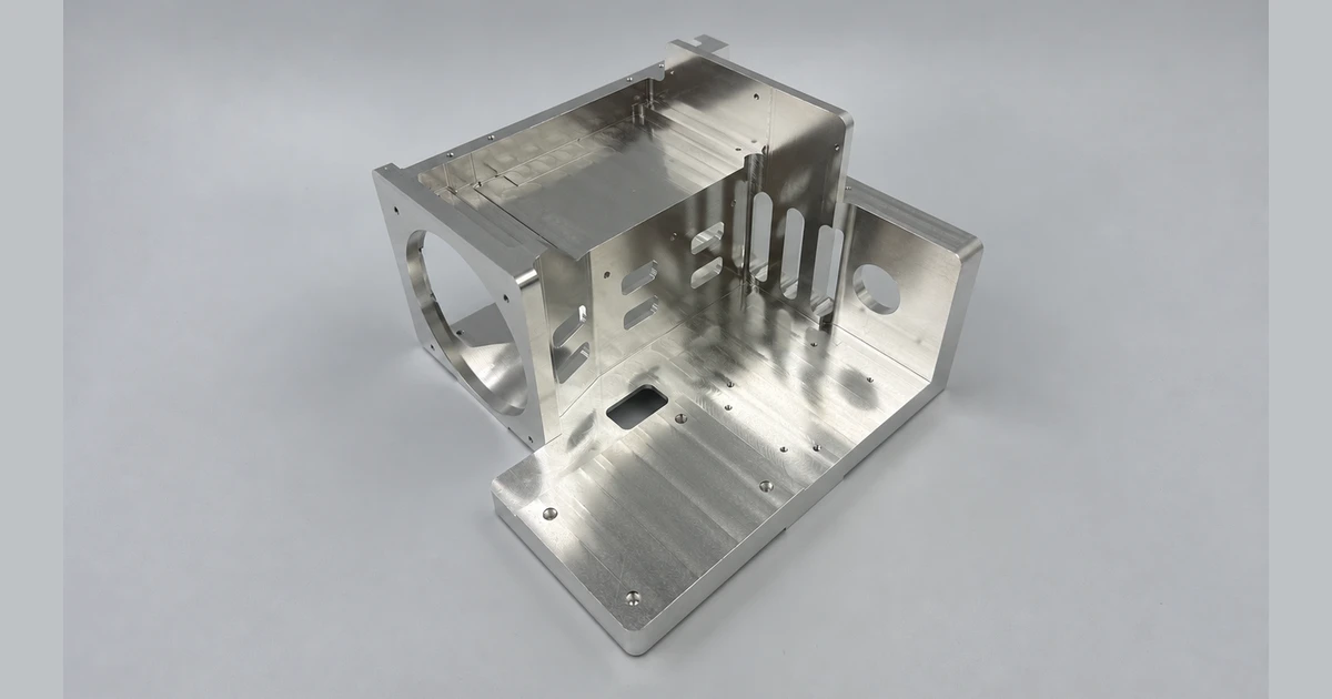
Machining opposite faces usually requires access from another direction. After a flip, how the part is located and seated affects the relationship between the new face and the existing reference. Chips, unsuitable contact areas, or a changed clamping condition can compromise that relationship even when each individual face is machined cleanly.
Plan the locating features and support surfaces before finishing the related faces. Where access requires multiple setups, the datum relationship must survive the transfer. See our guide to datum transfer across CNC machining setups for the broader setup problem.
CMM inspection needs a suitable measurement plan
We use CMM inspection for flatness and parallelism requirements. The machine provides measurement capability, but the result still depends on the feature definition, point coverage, support, datum establishment, and evaluation method.
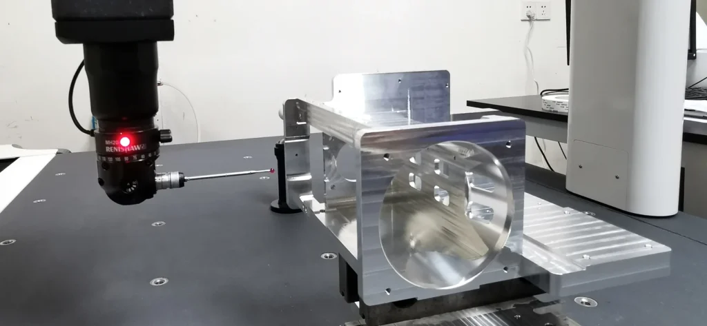
For flatness, distribute measurement locations across the controlled area so the check can detect relevant surface variation. A few convenient locations can miss a local high region or bow between them. For parallelism, measure the datum feature and the controlled surface with a plan appropriate to their relationship. Do not substitute an unrestricted best fit of the controlled face for the required datum-based orientation.
The software calculation also matters. Hexagon’s plane fitting documentation distinguishes least-squares fitting from minimum-separation fitting. These methods optimize different quantities. A peak-to-valley value about a least-squares plane should not automatically be described as a minimum-zone result. Select and record the evaluation method appropriate to the drawing and inspection agreement.
When results differ between supplier and customer, compare the inspection conditions before concluding that either instrument is wrong. Useful items to compare include:
- Drawing revision, controlled area, and feature identification.
- Part orientation, support locations, and restraint.
- Datum establishment and alignment used for parallelism.
- Measurement coverage and the evaluation settings.
- Surface cleanliness, finishing state, and relevant measurement conditions.
The report should identify the requirement and measured result clearly enough for the customer to relate them to the drawing. A photograph of a CMM setup helps explain the inspection context, but does not by itself establish a tolerance value or a pass result. Our CNC machining inspection guide covers complementary checks.
Questions to resolve before production
If a drawing has a flatness callout but the assembly also depends on the relationship to another face, ask the designer whether an orientation requirement is needed. Do not add a parallelism tolerance independently or assume one from the appearance of the CAD model.
If the drawing specifies both controls, inspect each against its own requirement. If a part shows a local gap, describe that observation and its location without converting it into an unsupported geometric result. If inspection reveals a deviation, communicate the measured characteristic and the conditions to the customer; acceptance or a drawing change requires the appropriate agreement.
For a CNC machining quotation, send the 3D model together with the controlled 2D drawing. Identify the assembly faces, required finishing state, and any special support or restraint conditions. That information lets machining and inspection be planned around the same requirements.