Stainless steel galling can make a threaded connection difficult to tighten or dismantle even when the components were manufactured to the specified thread requirements. Preventing it requires attention to both the machined parts and the conditions in which they are assembled. Material pairing, surface condition, lubrication and tightening practice all belong in that review.
At SAMSHION, we machine threads to the customer drawing and check them with thread gauges before dispatch. That inspection provides the agreed acceptance check for the manufactured thread. Assembly performance involves the actual mating component and operating conditions, which need their own requirements when resistance to galling matters.
This guide explains stainless steel thread galling, how it differs from other causes of a tight connection, and what engineering and purchasing teams should specify before ordering CNC machined threaded parts. It focuses on practical drawing and inspection decisions for custom components.
What Is Galling in Stainless Steel
Galling is a form of adhesive surface damage that can occur when loaded metal surfaces slide against one another. Local contact can disrupt the protective oxide film, exposing metal that adheres to the opposing surface. Material transfer and raised areas can then increase interference and friction. Severe damage can seize the connection. TWI describes this mechanism and its relevance to threaded fasteners.
In a threaded connection, the sliding contact is along the engaged thread flanks during tightening or removal. An assembler may notice increasing resistance, rough movement or a connection that stops turning. The damage can affect either member, including an expensive custom housing as well as the replaceable fastener.
The practical engineering question is which conditions the joint must tolerate. A connection assembled once under a controlled procedure presents a different review from an adjustment thread that is moved repeatedly. The expected use should accompany the part drawing so that manufacturing acceptance and assembly requirements can be planned together.
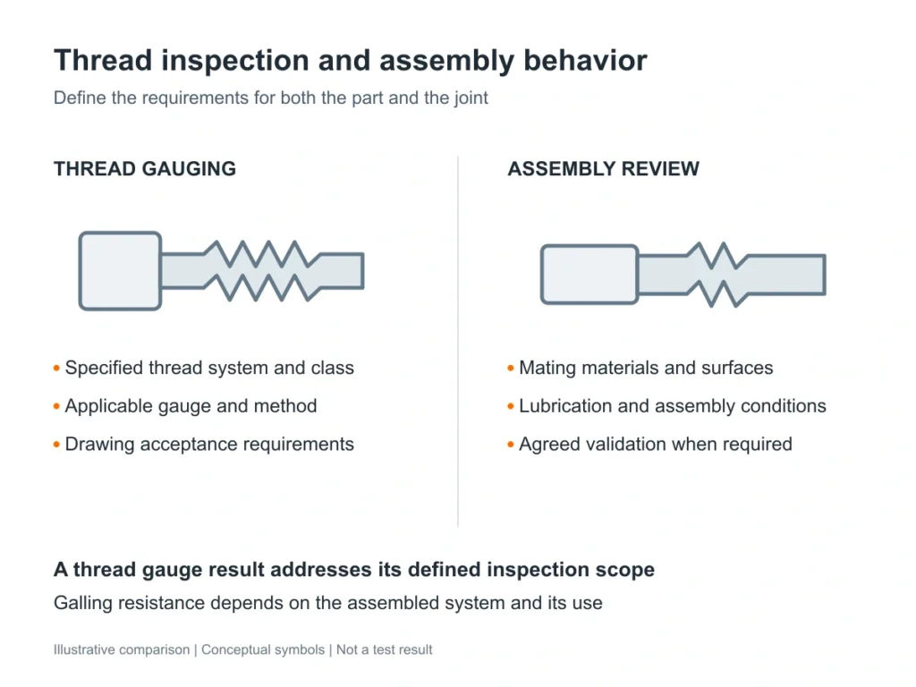
Why a Thread Gauge Pass and Galling Resistance Are Different Checks
What Thread Gauging Establishes
A thread gauge evaluates the thread according to its type, designation and applicable acceptance method. The drawing must identify the thread system, nominal size, pitch and class. Gauge selection and use must match that requirement. For example, the published scope of ASME B1.2 covers gauges and gauging for Unified inch screw threads; other thread systems require their corresponding requirements.
Where GO and NO-GO thread gauges are specified, their use and acceptance rules follow the applicable system. Avoid transferring an engagement rule from a different thread standard or gauge type. The inspection plan should identify the required method.
A gauge record should be read within that scope. It does not reproduce every contact condition of a production mating part. Its result also does not establish a particular assembly torque, preload or resistance to damage over repeated assembly cycles. Those are separate characteristics of the joint and its use.
Specify any additional checks explicitly. Usable thread depth, hole position, entry condition and nearby features may require verification beyond the selected thread gauge. A blind threaded hole can meet its gauging requirement while a supplied screw is too long for the available bottom clearance. That interference needs a dimensional review rather than an assumption about galling.
Define Any Required Assembly Verification
If the customer requires a trial with a particular mating part, identify that part and its revision. Agree the surface and lubrication condition, assembly procedure, number of cycles and acceptance criteria before testing. A hand fit with an unidentified screw provides different information from a controlled trial with the specified production components.
For our machining orders, the drawing remains the basis for manufacture and inspection. Any additional assembly verification should be agreed as a separate part of the project scope. Our CNC machining inspection guide explains how feature requirements and inspection methods should be connected.
Galling Versus Cross Threading and Other Assembly Problems
A connection that feels tight needs investigation before its cause is named. The observations below help organize that investigation; they are not a diagnosis from appearance alone.
Cross threading concerns incorrect engagement of the thread paths. Galling concerns adhesive damage at loaded sliding contact. The two conditions can also occur together, so forcing a damaged connection does not provide a reliable way to tell them apart.
Keep both components available for review. A damaged male thread alone may not show what was present in the female thread, whether a coating was applied, or how the connection was started. Part identity, photographs and the assembly sequence help the responsible engineers decide what to inspect next.
Material Pairing Needs More Than a Stainless Steel Label
Review the Two Mating Materials Together
Provide the specified grades and material conditions for both members. The label stainless steel leaves open important differences in composition, hardness, corrosion behavior and manufacturing route. If one member is a purchased fastener, its specification should be reviewed alongside the custom part drawing.
Changing from a 304 component to a 316 component should not be treated as a guaranteed solution to stainless steel galling. The Nickel Institute’s fabrication guidance discusses the limits of a simple 304 and 316 pairing. Grade selection must also meet the application’s corrosion and mechanical requirements.
Our 304 versus 316 versus 17-4PH machining guide provides broader material-selection context. A proposed alternative should return to the design owner for approval rather than becoming an unrecorded shop substitution.
Keep Material Changes Consistent Across the Order
A material revision can affect more than machining. Purchasing documents, the drawing, material records, any subsequent treatment and the mating-component specification must describe the approved combination. An updated part made from a different grade should not reach assembly under the old identification.
If a supplier proposes a treatment or material intended to improve wear behavior, request the relevant evidence and its conditions. A result for a particular test pair or laboratory procedure needs interpretation before it is used as the acceptance basis for a different component and joint.
Thread Design and Machining Details to Review
Complete the Thread Callout and Entry Geometry
State the thread standard, size, pitch, class and required engagement. For blind holes, distinguish usable full thread from drilled depth and account for the mating component’s end geometry. Counterbores, shoulders and surrounding walls must leave the intended access for cutting, gauging and assembly.
Entry chamfers and thread starts should follow the drawing and applicable specification. Where an assembly approach is restricted, show that condition during design review. A feature that is easy to reach on a loose component may become difficult to engage once the surrounding parts are installed.
The CNC threaded hole guide covers tapping, thread milling and drawing inputs in more detail. Those methods should be selected for the required geometry and material; the method name alone does not establish the performance of the assembled joint.
Control Burrs and Surface Condition Without Changing the Thread
Review burrs, damaged starts and residual chips before release. The Australian Stainless Steel Development Association’s galling guidance includes cleanliness, fit and careful deburring of machined threads. A request for a good surface should be translated into the relevant drawing requirement or agreed appearance and inspection criteria.
Corrective work must preserve the specified profile and dimensions. Handwork at an entry or intersection should not silently remove a functional part of the thread. If the proposed cleanup would change the drawing feature, obtain approval and establish the required inspection afterward. Our deburring guide for machined parts discusses this relationship between edge control and feature acceptance.
Treat thread position, orientation and surrounding geometry as separate drawing items. Their inspection should match the assembly interfaces they control. A thread gauge result should not be used as the record for a hole-position or mounting-face requirement that was never measured by that method.
Lubrication and Tightening Conditions Belong in the Assembly Plan
Lubrication can influence friction at the mating surfaces, but the selected product must suit the actual application. State whether parts are supplied dry, with an agreed protective film, or for a later cleaning and lubrication operation. Leaving that state unspecified can cause the assembler to work from a different assumption than the supplier.
Adding a lubricant can also change the relationship between tightening torque and the achieved preload. Nord-Lock explains why lubrication and reuse affect this relationship. The approved assembly procedure should account for its friction condition. A torque value intended for one condition should not be carried over automatically after that condition changes.
For a custom joint, identify who supplies the assembly instruction and who approves changes. Include the mating components, surface condition and required equipment in that instruction. Where installation speed or repeated adjustment is important, define those conditions for the application and any validation rather than setting one universal value for every stainless steel thread.
Cleaning and handling instructions should preserve the intended condition until assembly. If a customer cleaning operation removes a specified film, the next step must restore the approved assembly condition where required. Packing should also prevent damage to exposed thread starts and keep contact surfaces separated from loose debris.
Surface Treatments Require Their Own Dimensional Review
A surface treatment may be considered as part of a joint design, but its name does not establish a universal anti-galling result. The British Stainless Steel Association reviews wear and galling resistance in relation to surface behavior and treatment options. The proposed route still needs to suit the substrate and service conditions.
Specify the actual treatment and its acceptance requirements. If a deposited coating occupies space on a thread, the manufacturing plan must account for the required final condition. Identify any excluded surfaces, treatment sequence and checks after treatment before the machined sizes are released.
Do not use a photograph or a generic finish description as the complete specification. A visually similar surface can have a different preparation, thickness or friction condition. Our surface finishing overview can help organize the available routes for a project-specific review.
What to Record When a Connection Becomes Difficult to Turn
Unexpected resistance deserves review before further force is applied. Record when it occurs, including whether the connection was just starting, partly engaged, at its intended seating position or being removed. That sequence helps distinguish an entry problem from bottoming or damage developed during movement.
Preserve both mating components and identify their part numbers, revisions, materials and surface conditions. Note the tool, assembly instruction, lubricant and any prior cleaning or reuse. Clear photographs of the thread starts and affected areas can support discussion, while physical inspection may still be needed to establish the cause.
Rework should follow an engineering assessment. Chasing a damaged thread can remove evidence and may alter the specified profile or fit. Agree whether to inspect, repair or remake the component, then define the acceptance checks for any approved corrective work. A decision for an easily replaceable screw may differ from the decision for a custom housing.
Separate Part Acceptance From Joint Performance Requirements
For custom stainless steel threaded parts, an RFQ should make the inspection boundary clear. The manufacturing supplier needs the drawing and agreed acceptance methods. The joint designer or assembler needs the conditions under which the accepted components will be installed and used. Where those activities overlap, define the required handoff and evidence.
For example, consider a hypothetical machined housing with a threaded opening and a separately purchased screw. The housing drawing defines its thread and surrounding geometry. The screw specification establishes the matching thread and material. An assembly instruction then defines engagement and tightening. A change to any one of those documents may require the others to be reviewed.
The quotation should identify any requested dimensional report, thread inspection record, material document or assembly trial. Each serves a particular purpose. A customer requesting a demonstration of galling resistance needs to define the trial conditions and approval criteria so that the work can be assessed and quoted accurately.
Information to Provide With a Threaded Part Enquiry
Send the model and drawing together, including the details needed to connect machining with the intended assembly:
- Part number, drawing revision and quantity.
- Specified stainless grade and material condition.
- Thread system, size, pitch, class and usable engagement.
- Through or blind condition, entry geometry and access constraints.
- Critical hole positions, orientations and nearby mounting features.
- Mating-part drawing or fastener specification where relevant.
- Surface treatment and the condition in which dimensions apply.
- Cleanliness, protective film and packing requirements.
- Required inspection methods and documentation.
- Any assembly trial, operating conditions and acceptance criteria to be agreed.
SAMSHION can review the machining and inspection requirements against the drawing. Share the mating-component information when a thread forms part of a sensitive interface, and identify any additional assembly work during quotation. Send the files through our project quotation page.
Common Questions About Stainless Steel Thread Galling
Can Stainless Steel Threads Gall After Passing a Thread Gauge
Yes. The gauge checks the thread under its applicable acceptance method. The production mating material, lubrication and assembly conditions remain relevant to galling risk. A requirement for assembly performance needs a defined verification method beyond the selected dimensional check.
Is Galling the Same as Cross Threading
They describe different mechanisms. Cross threading concerns incorrect thread engagement, while galling involves adhesive surface damage during loaded sliding. Examine both mating parts and their assembly history because damage can involve more than one mechanism.
Does Pairing 304 With 316 Prevent Galling
That pairing alone should not be relied on as a guarantee. Review the actual grades, conditions, surface state and assembly requirements. Any material change also needs to satisfy the joint’s corrosion and mechanical requirements.
Should Every Stainless Steel Thread Be Made Looser
Use the fit and class required by the design. Changing clearance may affect alignment, engagement or other functions. If the design needs revision, approve and document the new requirements before machining and select the corresponding inspection method.
Does a Smooth Looking Thread Prove Galling Resistance
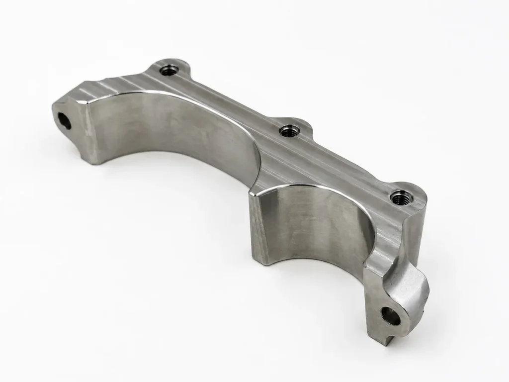
No. A photograph or visual impression cannot establish the joint’s resistance under load. Surface requirements, dimensional acceptance and any assembly trial need their own definitions. Product images are useful for explaining geometry, not for demonstrating unperformed tests.
What Does SAMSHION Check Before Dispatch
We machine to the customer drawing and use thread gauges to inspect the specified threaded features before dispatch. Other drawing characteristics follow their agreed inspection requirements. Additional assembly trials or performance verification must be defined and agreed for the project.