Injection molded threads are formed directly in a plastic part during molding. They can connect a cap to a housing, locate a component or secure a fitting without a separate thread-cutting operation. A usable threaded connection, however, depends on more than reproducing a helical shape in CAD. Both parts must engage, reach the intended seated position and carry their service loads without damage.
For a drawing review or supplier enquiry, start with three decisions: how the part mates, how the thread leaves the mold and how the finished connection will be checked. This guide connects those decisions using two SAMSHION projects. The PP assembly uses different release methods for its two components, while the ABS water pump component is molded without rotational release. Their actual trial assembly methods are described in the case section.
Choosing between molded threads and other threaded connections
Choose the connection method before committing to tooling. An economical mold is of little value if the plastic thread cannot withstand the intended assembly conditions. Conversely, a metal insert can add unnecessary hardware and handling when an integral plastic connection already meets the requirements.
Molded plastic threads make sense when the thread can be released from the tool and its strength, wear and dimensional behavior meet the application. Adding the thread to the molding operation can avoid secondary machining, but a complicated release mechanism may increase tooling investment or cycle time.
Machining a thread after molding may be worth evaluating for limited quantities, difficult access or a requirement that is expensive to reproduce directly in the mold. The comparison should include fixturing, extra handling and inspection, rather than only the machining time.
A metal threaded insert provides a different interface. It may suit repeated fastening or higher loads, although the surrounding plastic still has to resist insert rotation, pullout and assembly stress. Our insert injection molding guide explains the design considerations when metal components are molded into plastic. Molded plastic threads and molded-in metal inserts should not be treated as interchangeable terms on a drawing or quotation.
Plastic thread design starts with the mating assembly
Define the complete thread specification
Specify the thread standard or custom profile, nominal diameter, pitch, direction, number of starts and effective engagement length. Identify the mating part and its revision. For a custom thread, supply dimensioned geometry for both sides instead of expecting the toolmaker to infer the fit from a shaded model.
A thread callout must also establish whether the interface is straight or tapered. Threads with similar diameters can have different profiles or pitches and must not be treated as compatible because they engage for one turn. Where an existing purchased component fixes the interface, obtain its specification or an approved drawing before changing the plastic thread.
Pitch describes the spacing between adjacent thread forms. Lead is the axial travel in one revolution; it equals pitch multiplied by the number of starts. Confusing these on a multiple-start thread can produce components that look similar but cannot assemble correctly.
Review the profile and supporting wall
Fine, sharp thread features can be vulnerable to damage and difficult to reproduce consistently. Review tooth thickness, root radii and the wall behind the thread together. Increasing thread depth may improve contact in one location while reducing the remaining wall or making release harder elsewhere.
For a new custom pair, a rounded root or less delicate thread form may be worth evaluating. For an existing standardized counterpart, preserve compatibility rather than changing the profile solely to simplify molding. The selected form must carry the required load and still clear the tooling during release. A coarser pitch is a design option, not an automatic improvement for every connection.
Control entry and final seating
A suitable entry chamfer or lead-in helps the components align before the load-bearing threads engage. The first thread, nearby ribs and available hand or tool access should allow the operator to start the connection without forcing it sideways.
Define what stops tightening: a shoulder, a flange, a specified position or another controlled feature. Check that the threads do not bottom out before the intended surfaces meet. Excessive tightening can distort a thin housing even when the thread itself survives. Drawings should distinguish the useful engagement from incomplete entry and runout regions.
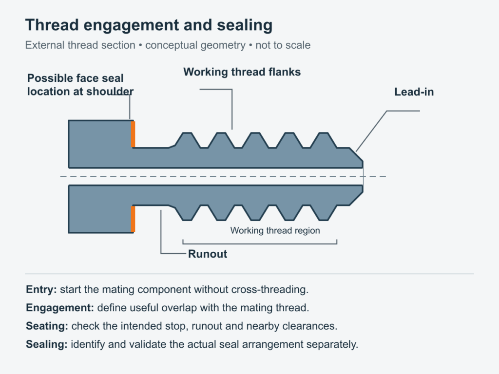
Consider a cap that appears tight but leaves a visible gap at its intended seat. The obstruction could be an incomplete thread, a shoulder in the wrong position or contact elsewhere on the assembly. Increasing tightening force does not distinguish these causes. Check the stopped position and contact location before increasing thread clearance or changing the seal.
Keep the full assembly visible during design review
The outside of a threaded component can also determine whether it is practical. A nearby flange may obstruct cavity movement; a long flexible neck may bend during tightening; a rib can make local wall thickness uneven. Provide the complete part and mating assembly for DFM, not only a cropped thread model. Identify which surfaces are cosmetic and which must locate, seal or transmit load.
Internal and external threads need different release reviews
Injection molded external threads
An external thread may be formed by cavity sections that move away from it. Placing the thread axis in the mold parting plane can allow each half to release part of the circumference. The complete component still matters: a flange, surrounding wall or nearby undercut may obstruct that movement.
Where a parting line crosses the thread, review mismatch, flash and their effect on engagement. A small ridge that is acceptable on a nonfunctional surface may cause noticeable drag on a thread. Covestro’s Part and Mold Design guide discusses molded threads and the influence of parting-line placement. The selected construction must suit the actual part rather than only an isolated thread section.
Injection molded internal threads
An internal thread surrounds the steel that forms it. Pulling a rigid threaded core straight out can mechanically interfere with the molded profile. The review therefore needs a way to disengage the thread, retract the forming features or allow a suitable profile to pass over the core without unacceptable damage.
This does not mean every internal thread requires an automatic unscrewing mold. Access, resin behavior, thread depth and geometry may support other methods. Conversely, a shallow-looking thread should not be assumed safe to strip without evaluating the part’s deformation and recovery.
Selecting a release method for injection molded threads
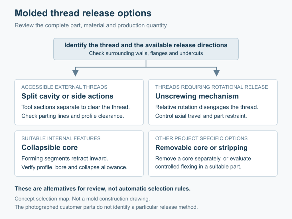
The first question is which forming surfaces obstruct release. Accessible external features may clear with the cavity halves. An enclosed internal profile needs a route to disengage the forming core. The following approaches describe those options; the confirmed methods for the photographed components appear in the case section.
Split cavities and side actions
Cavity sections separate to clear accessible external thread features. This can avoid rotating the part or threaded forming surface, but the opening directions must clear the entire profile. Review where the sections meet, how they locate and how any witness line affects the assembly. A design that releases between the two mold halves may need no separate side action. Where additional side actions are necessary, allow space for movement and reliable return positioning.
Unscrewing molds
An unscrewing mechanism creates relative rotation and axial movement between the threaded forming surface and the part. The design needs a controlled way to keep the other member from rotating unintentionally. Vega’s thread unscrewing guidance describes the relationship between rotation, axial travel and mechanism selection.
The quotation should account for the required travel, drive arrangement and available machine interfaces. Release must be complete before the next motion can damage the part or tool. Maintenance access and repeatable return to the molding position matter alongside initial cycle performance.
An important detail is how the molded component resists the release torque. Relying on an uncontrolled grip can allow it to rotate with the core. Any feature used to hold the part must withstand that operation and leave acceptable marks. The product designer and tool designer should agree this interface before the external appearance is finalized.
Collapsible cores
A collapsible core retracts forming segments inward to clear an internal feature. Whether it is practical depends on the bore, undercut depth, available collapse and the particular core design. DME’s collapsible core design guide provides model-specific requirements and operating sequences.
Do not assume that every segmented core can produce the same continuous thread. Review the intended profile, segment boundaries and clearance with the component supplier. Features left by the segmented construction must also be acceptable on the finished part.
Removable cores and controlled stripping
For suitable projects, a threaded core can leave the mold with the part and be removed separately. This trades some automatic mechanism complexity for handling and a controlled removal operation. Production quantity and the risk of inconsistent handling influence the economics.
Controlled stripping relies on a suitable plastic part flexing over the core and recovering. It requires a compatible material, thread profile and supporting geometry. It is not simply a stronger ejection stroke. Damage, permanent distortion and assembly performance need to be checked after release.
Material and shrinkage affect the final fit
The material specification should identify the grade, fillers, color system and relevant service conditions. PP and ABS can both appear in threaded components, as the examples here show, but those examples do not make the materials interchangeable or establish a universal torque rating.
Shrinkage changes dimensions between the tool and the finished part. Nonuniform shrinkage can also change shape, including roundness around a threaded opening. The same nominal material family can behave differently with grade, processing and local wall geometry. Autodesk’s shrink analysis explanation describes why tooling allowance considers both material and molding conditions.
For the assembly, examine both tolerance limits. The tightest pair must engage without damage; the loosest pair must retain the intended function. Testing only one convenient pair may miss combinations that occur across cavities or later batches.
Specify the condition in which dimensions and assembly fit are evaluated. A freshly molded part and a part checked after agreed conditioning are not necessarily comparable. If a material, filler or color formulation changes, review the effect on the accepted process and fit rather than assuming that an unchanged CAD file guarantees an unchanged assembly.
Long-term loading introduces a separate consideration. Plastics can creep or relax under sustained stress, particularly as temperature changes. A connection that feels tight immediately after assembly may behave differently after service exposure. The required test duration and environment should follow the product’s actual use rather than an arbitrary tightening exercise.
Thread engagement and sealing require separate checks
A smooth screw connection does not by itself demonstrate a leak-tight assembly. Depending on the design, sealing may depend on a gasket, an O-ring, a seating face or a specified thread-sealing arrangement. Identify the actual sealing interface before choosing the acceptance test.
For an O-ring design, gland dimensions, squeeze, material compatibility and mating surfaces are relevant. The Parker O-Ring Handbook is a reference for this separate seal-design task.
If leak performance is required, agree the test medium, pressure or vacuum, temperature, duration and allowable leakage. State whether the test applies before or after repeated assembly or environmental exposure. Increasing tightening torque is not a substitute for finding the source of a leak and can damage the plastic connection.
Two SAMSHION threaded component examples
PP automotive components with mating threads
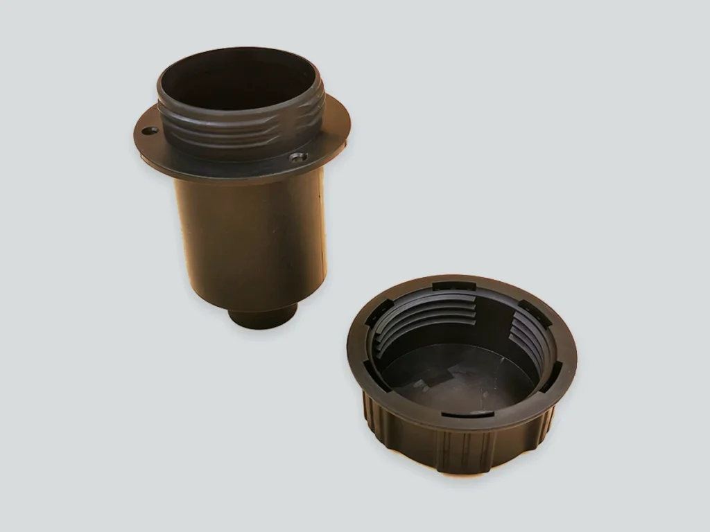
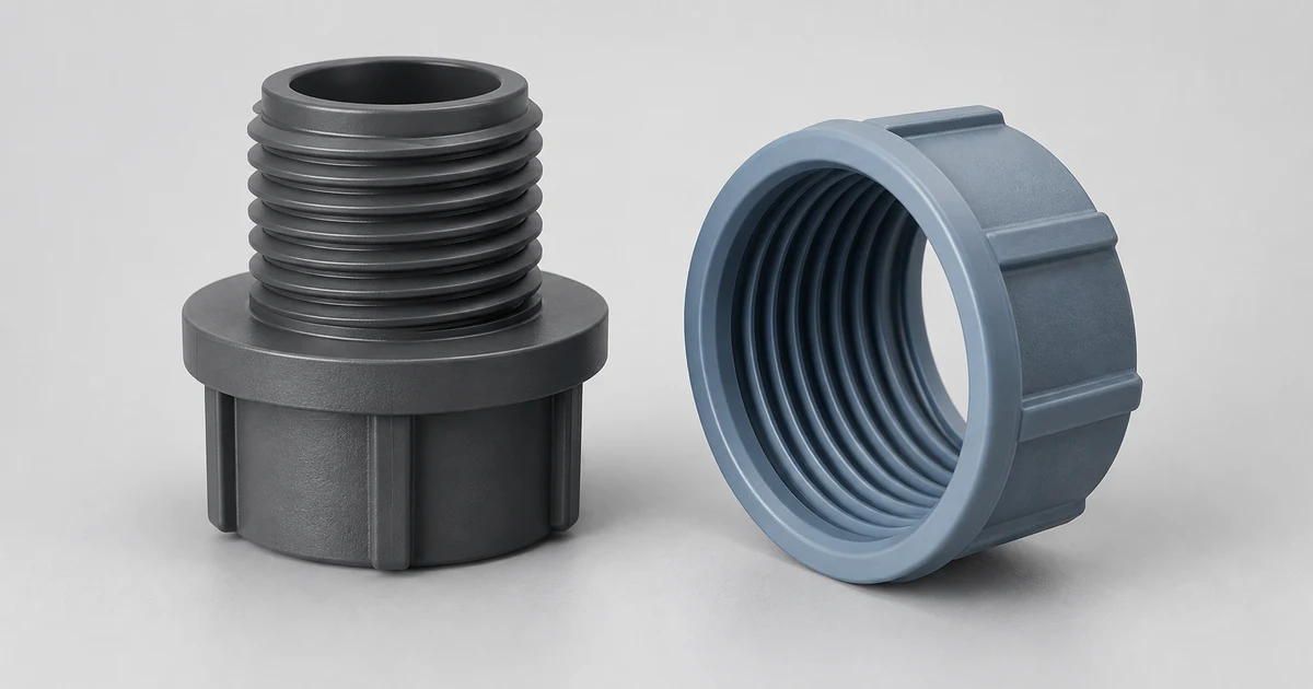
These PP automotive components are designed to assemble with each other. We mold the external thread on the cylindrical body using a two-half mold release arrangement. The cap with the internal thread uses rotational unscrewing. Both threads are formed during injection molding, despite the different release methods.
At SAMSHION, we check their fit by trial assembling the two molded components. Project requirements include thread fit, smooth engagement, assembly dimensions and appearance. The assembled components also have sealing requirements, which are separate from the trial assembly check.
The useful lesson is that mating threads do not have to use the same tooling approach. Each component must first release from its own mold; the resulting parts then need to work as a pair. Where two molded components are supplied together, checking them together addresses an interface that separate visual inspections cannot fully evaluate.
We retain the production tooling at SAMSHION and manufacture these components according to repeat customer orders. The interval between orders is not fixed. The project information here describes the manufacturing and fit-check methods, not a published torque rating or leak-test result.
ABS water pump component with an external thread
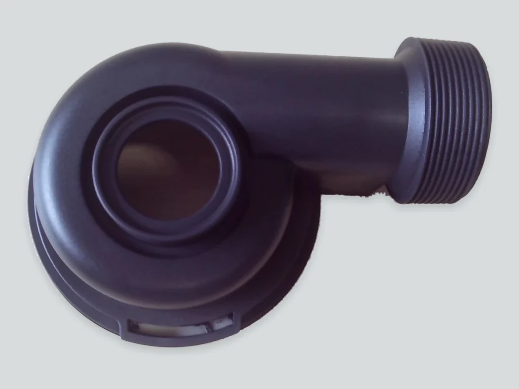
We injection mold this ABS water pump component as a single piece, including the external thread. It releases through the two mold halves and does not need rotational unscrewing. Fit is checked by trial assembly with a mating component supplied by the customer. The part is produced for repeat orders placed as needed.
Unlike the PP pair, this check uses a customer-supplied counterpart. For this type of arrangement, the sample identity and drawing revision should remain clear: a replacement or revised counterpart can change the assembly requirement even if the molded component drawing has not changed.
The two examples show why the enquiry should include the mating component and its specification, as well as the molded-part drawing. Our production mold making and repeat supply services explain how tooling is planned and retained for ongoing orders.
Investigating common plastic thread assembly problems
Record where a problem occurs before changing the thread dimensions. Compare several samples and, where relevant, keep cavity identity and mating-part revision visible in the findings.
For example, if one cap runs freely on several bodies but another repeatedly catches at its parting line, that comparison narrows the investigation. It does not yet prove whether the cause is tooling mismatch, flash or deformation. Keep the suspect samples, locate the interference and check the relevant feature before enlarging the entire thread.
Use a defined comparison rather than repeatedly trying the same pair. First inspect the parts for debris or visible damage. Then exchange one member at a time while keeping the assembly method unchanged. If available, compare results with an approved counterpart. Record the position at which resistance begins and whether the intended seating face is reached. This sequence helps identify which component or region needs dimensional investigation.
Hand feel can reveal an obvious catch, but it is not a numerical torque specification. If different operators disagree about whether a connection is acceptable, agree a measurement method or a reference assembly before correcting the tool. Otherwise the factory and customer may be judging different things under the same description of a smooth fit.
Define the thread inspection and assembly check
The drawing should define the critical dimensions and how the part is located for measurement. Inspection can combine dimensional checks with an agreed functional gauge or mating component. A functional fit check does not replace dimensions that are important for interchangeability, and a dimensional report alone may not describe the tightening behavior.
Where required, define starting torque, running torque, final tightening conditions and the number of assembly cycles. Use controlled counterparts and an agreed method. Flexible parts should not be squeezed into a measurement fixture in a way that hides their free-state shape. Our T1 sample approval checklist covers the broader sample-review process.
Record enough information to repeat the check
A useful assembly record identifies the molded-part revision, material, batch or cavity where relevant, counterpart and test conditions. Record whether the thread starts correctly, completes its intended travel, reaches the seat and can be removed without damage. Add numerical results only for measurements actually performed. An agreed functional gauge may help, but its purpose and acceptance criteria should be defined for the specific thread.
For repeated assembly, inspect the connection again after the agreed number of operations. A satisfactory first assembly does not establish resistance to wear or misuse. Equally, a fit test at room temperature does not establish behavior under the full service environment. Keep assembly fit, strength and sealing as separate acceptance items where the application requires them.
Consider interchangeability across repeat orders
If new caps must fit bodies from earlier production, include that requirement in the approval plan. For appropriate projects, cross-checking selected new and retained counterparts can reveal differences that a same-batch pair might hide. Retained parts need identification and suitable storage; an aged or damaged sample should not silently become the acceptance standard.
These are suggested checks to agree with the customer. They do not imply that every project needs the same sample size, gauges or test program.
Compare tooling investment with the cost of accepted assemblies
Compare the total cost of accepted assemblies, including tool construction, release time, handling, secondary operations and inspection. An automatic mechanism is not automatically the best investment for irregular small orders. A manual operation may become unattractive when demand rises. The decision should use expected batch sizes and repeat demand, not only the first purchase quantity.
A simple break-even comparison can make this discussion concrete. Suppose an alternative tool costs an additional USD 2,400 and saves USD 0.12 per accepted part in recurring processing cost. Under those assumptions, 20,000 accepted parts recover the extra tooling investment. This is an illustrative calculation, not a SAMSHION quotation or a forecast for the photographed projects.
The result changes if maintenance, scrap, inspection, setup or design changes alter either option’s cost. It also says nothing about whether both options meet the functional requirement. Ask suppliers to compare the same material, part revision, quality scope and order assumptions; otherwise a lower unit price may simply exclude work included in the other quotation.
Information to include with a threaded part enquiry
- Current CAD models and dimensioned drawings for the molded part and its counterpart.
- Thread specification, number of starts, useful engagement length and intended seating position.
- Resin grade, color, fillers and any applicable environmental or chemical exposure.
- Initial order quantity, likely repeat quantities and expected assembly or disassembly frequency.
- Critical dimensional requirements, fit checks and any agreed torque, retention or leak tests.
- Acceptable parting lines, surface marks, gate locations and cosmetic areas.
If a detail is still under development, identify it explicitly. It is usually more useful to review an unresolved fit before tooling release than to hide it behind a generic instruction such as “must screw smoothly.”
Frequently asked questions
Can internal and external threads both be injection molded
Yes, when the part geometry, material and release method are suitable. Internal and external threads need different access and interference checks, so feasibility should be reviewed on the complete component.
Do all injection molded threads need an unscrewing mold
No. Accessible external threads may use split cavity sections. Some internal features can use collapsible or removable cores, while controlled stripping is limited to suitable designs and materials. The appropriate method depends on the actual geometry.
Can a molded plastic thread replace a metal insert
Sometimes, but the decision must consider fastening loads, repeat use, wear, service conditions and the surrounding plastic structure. A metal insert and a molded plastic thread provide different interfaces and should be evaluated as alternative assembly designs.
Why can a threaded part screw on but still leak
The threads may position and retain the components while a separate seal closes the fluid path. Verify that the intended sealing surfaces meet and that the specified seal is correctly installed. A smooth rotation check cannot establish a pressure or leakage rating.
Should trial assembly use the actual mating component
Use an identified, appropriate counterpart or an agreed functional gauge. For the PP project described here, SAMSHION trial assembles the two molded components. For the ABS water pump component, the customer supplies the mating part. The counterpart should represent the approved interface rather than any available piece that happens to screw on.
What tolerance should be specified for molded threads
Use the applicable thread specification and functional needs of the mating assembly. Feasible tolerances depend on geometry, material, tooling and measurement conditions. One tolerance value should not be applied to every threaded plastic component.
Discuss your threaded injection molded part
Send SAMSHION your part drawing, mating-component information, material and expected quantities. We can review the molding requirements and quote the agreed tooling and part-supply scope. Request a quotation for your injection molded threaded components.