The first injection-molded samples have arrived. The shape looks right, the color is close, and one part fits into the assembly. Is that enough to approve the next batch?
Not necessarily. A useful T1 review connects each sample to a drawing revision, material, trial condition and acceptance requirement. It should answer three questions: what has been demonstrated, what still needs correction, and what work can now proceed?
For projects using rapid tooling for prototype and low-volume injection molding, this distinction matters. Early parts may support development decisions before every production requirement is closed. This guide explains how to inspect those samples, investigate conflicting findings and give feedback that leads to a clearly defined next trial or approval.
What Does T1 Mean in Injection Molding
In this guide, T1 means the initial mold-trial samples submitted for the agreed customer review. Toolmakers may use T0, T1 and later trial numbers differently. Confirm the naming and expected deliverables with the supplier rather than assuming that the label guarantees a particular level of completion.
A trial number identifies a development stage. It does not automatically establish that final texture, dimensional inspection, assembly testing or production qualification is complete. Likewise, a quoted date for T1 samples is not necessarily the date on which approved production parts will be available.
Start by defining the decision the trial must support. An engineering team investigating an uncertain interface may need fit evidence first. A team preparing a pilot build may also need repeatable assembly results, agreed appearance and a documented disposition of open issues. The inspection plan should reflect that difference.
Confirm the Sample Package Before Testing
Prepare one review folder that links the physical parts to their supporting information:
- Part number, released CAD model and controlled drawing revision.
- Sample identifiers, trial date, tool revision and cavity identification where relevant.
- Actual resin manufacturer, grade and color, with the agreed material documentation.
- Dimensional results, trial information and other evidence included in the project scope.
- Known exceptions, such as temporary inserts, unfinished texture or planned corrections.
- The intended decision, reviewers and required response date.
A missing document and a failed characteristic are different problems. If the report belongs to another revision, first request the matching report; do not assume that either the supplied parts or the drawing are wrong. If the trial used a substitute resin, identify which conclusions must remain open until the specified grade is sampled.
Also plan the test sequence. Photograph and identify samples before assembly, sectioning or other tests that may alter them. Keep an unmodified reference where practical. A part that has been trimmed, repeatedly flexed or exposed to a test environment should not later be confused with an untouched dimensional reference.
Six Checks for Reviewing T1 Injection Molding Samples
1 Verify the Actual Resin and Trial Conditions
Confirm what was molded, not only what was ordered. ABS, PC/ABS or POM identifies a material family, not a complete commercial grade. Record the specified manufacturer, grade, color formulation and any agreed restrictions on substitutes or regrind. Request the relevant batch identification when material traceability is part of the scope.
Capture trial settings at the level needed to interpret the tests: machine identification, drying conditions, mold temperature and significant processing settings may be relevant. Separate samples made under different settings instead of treating the entire trial as one condition.
For standardized test specimens, molding conditions can influence measured properties. ASTM D3641 addresses specimen preparation and reporting; it is not a blanket acceptance procedure for every finished product. Use the applicable material and test requirements to determine what evidence is needed.
2 Inspect Critical Dimensions Against the Drawing
Begin with features that control the assembly: locating holes, mating profiles, sealing surfaces, fastening interfaces and other designated critical characteristics. Prioritizing these does not remove the obligation to complete the rest of the agreed inspection scope.
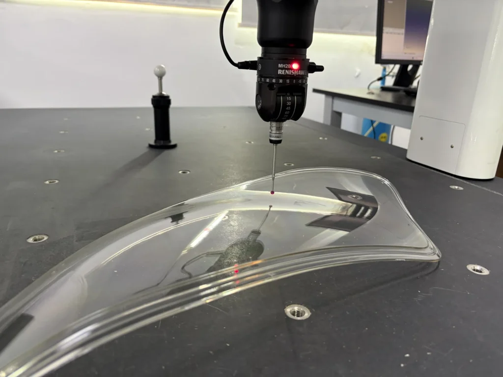
For each reported characteristic, check the nominal value, tolerance, actual result, sample identity and measurement method. A ballooned drawing can connect report entries to the correct features. A green pass indicator without the underlying result may be insufficient when investigating a disagreement or planning a correction.
Review the datum system and how the part is supported. Measuring a flexible component while clamped flat answers a different question from measuring its free-state shape. The setup should match the requirement being evaluated.
ISO 20457:2026 provides a plastics-specific framework for dimensional and geometrical tolerances and acceptance conditions. Apply the drawing, contractual requirements and standard edition agreed for the project; a newer publication does not automatically change an existing acceptance basis.
3 Review Appearance by Surface and Acceptance Reference
Inspect the relevant surfaces for specified concerns such as flash, sink, weld lines, discoloration, gate remnants, ejector marks and differences in texture or gloss. Identify where a finding occurs and whether that area is visible, hidden or functionally important in the finished assembly.
Use an overview photograph to locate the concern and a close-up to show it. Record lighting, viewing direction and the reference used for judgment. “The finish is poor” is less actionable than identifying a visible surface and the agreed appearance requirement it does not meet.
Do not approve unfinished work by implication. If texture or final color was intentionally excluded from T1, record it as pending. A photograph can help discuss a surface, but should not certify an exact finish grade. For terminology, see the injection mold surface-finish standards comparison guide.
4 Test Assembly Fit and Product Function Separately
A dimensional report and an assembly test provide different evidence. Record the mating-part revision, fastening sequence and relevant assembly conditions. Where required, evaluate insertion, engagement, clearance, movement or retention using the agreed test method and acceptance limits.
Do not quietly file an opening, trim an edge or force a sample into place and then report that it fits. Such adjustments may be useful for a development experiment, but the modified sample and the remaining problem must be identified.
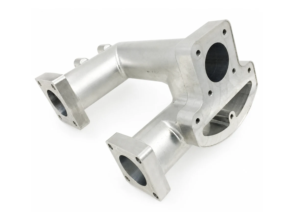
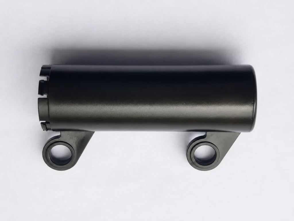
For a component with two fastening interfaces, for example, check both interfaces together in the intended assembly. Testing each opening separately may not answer whether their relative positions allow assembly. This is an illustrative review approach, not a claimed result for the component pictured here.
If the application requires repeated operation, leak testing or environmental exposure, define those tests separately. A successful first assembly does not establish performance throughout the intended use.
5 Align Conditioning and Measurement Timing
Record the interval between molding and inspection when it matters, along with the temperature, humidity and conditioning requirements in the test plan. Comparisons become difficult when one team measures newly molded parts and another tests differently conditioned samples without recording that difference.
ASTM D618 addresses conditioning plastics for testing because environmental conditions can affect results. Follow the applicable material specification and test method rather than assigning every resin the same waiting time.
Keep the physical state of the sample clear as well: unassembled, assembled, loaded or previously tested. If a later result changes, those records help distinguish a change in the part from a change in how it was evaluated.
6 Keep Cavity and Sample-to-Sample Results Visible
For a multi-cavity tool, retain cavity identification in both the sample set and the report. A pooled average can conceal a difference that needs cavity-specific investigation. For a single-cavity tool, sample-to-sample differences still deserve attention.
Ask how samples were selected and which trial conditions they represent. Parts collected while settings were changing should not be presented as one uniform production population. Equally, one carefully selected sample cannot describe all output from the trial.
Agree the sample quantity and selection method around the characteristics and project risks. Retain individual results where needed, not only averages. If variation is observed, identify whether it follows cavity, trial condition or sampling sequence before selecting the next investigation.
What If Your Measurements Disagree with the Supplier
Do not start by averaging the two reports or choosing the result that permits approval. First determine whether both teams measured the same characteristic on comparable samples.
A practical reconciliation sequence is:
- Confirm the drawing revision, feature number and units.
- Compare the same identified physical sample where possible.
- Exchange photographs or diagrams of the datum setup, support and measurement location.
- Check instrument suitability, contact method, software alignment and any applied measurement force.
- Align conditioning and the state of the sample, then repeat the comparison.
The goal is an agreed method that answers the drawing requirement. If one team measures a hole from a functional datum while another measures it from a convenient outer edge, both may obtain repeatable numbers while evaluating different relationships.
NIST’s guidance on gauge studies considers differences between instruments, operators and setups, as well as repeatability and stability. For a disputed critical feature, a proportionate measurement-system study may be more useful than immediately changing the mold.
Calibration also does not resolve every practical measurement issue. NIST explains that working conditions and other influences can introduce measurement bias even when an instrument has been calibrated. Ask how the complete method performs on this particular feature.
Until the discrepancy is resolved, mark the characteristic as under review. A measurement disagreement is not evidence that the part passes, and it is not yet a confirmed instruction to remove steel.
Choosing Between Process Adjustment and Tool or Design Changes
A visible symptom rarely proves its own cause. Describe the observation first, then organize the investigation. The following table is a discussion aid, not a troubleshooting recipe or a substitute for examining the actual tool and trial records.
When Process Evaluation Is Appropriate
If a proposed action changes molding settings, ask which observation it is intended to address and how the effect will be evaluated. Keep sample sets from the comparison identifiable. Improving one characteristic should not close the issue if another agreed requirement becomes unacceptable.
The objective is a repeatable, documented condition appropriate to the project, not a single favorable sample obtained during continual adjustment. Where further process development is needed, leave production approval open until the required evidence is available.
When Tool or Product Changes Need Separate Authorization
A proposed tool correction should identify the affected feature, the intended result and the required reinspection. Before machining, confirm that the requirement and diagnosis are agreed. Changes involving inserts, shutoffs, moving features or surrounding geometry need a review of their wider effects, not just the reported dimension.
A product-design change is a separate decision. If the drawing is revised to address an assembly need, release the new revision and record why it changed. Do not silently enlarge a tolerance merely to make an existing report pass. Confirm feasibility, quotation impact and timing before authorizing work outside the original scope.
Write Feedback That Can Be Closed Out
Use one issue log shared by the relevant reviewers. Each entry should identify the sample and cavity, drawing characteristic or surface, observed result, acceptance requirement and supporting photograph or measurement. Then add the proposed action, responsible person, target date and evidence needed for closure.
Keep observation, suspected cause and approved action in separate fields. “Opening does not align” is an observation. “Core position is wrong” is a hypothesis until verified. “Move the core” becomes an instruction only after the responsible teams approve that change.
For example:
The two fastening interfaces on the identified sample do not align with the mating component in the agreed assembly setup. Please confirm both part revisions and compare the relative feature positions using the drawing datums. Provide the proposed action and the dimensional and assembly evidence required for re-review. Assembly approval remains open.
This is an illustrative feedback example, not a SAMSHION customer inspection record.
Consolidate design, quality and purchasing comments before releasing instructions. Conflicting emails can otherwise leave the supplier uncertain about which revision or decision controls the next trial. Close an issue with evidence and an authorized disposition, not simply a message that work was performed.
What Should Be Rechecked on T2 or Later Samples
A later trial number does not show which issues were corrected. Request a change summary linked to the issue log, together with the updated tool or part revisions and the identity of the new samples.
Build the recheck around three groups: the characteristic that prompted the action, related characteristics that could be affected, and previously accepted requirements that the change may invalidate. For a changed fastening interface, this might include its dimensions, relative position, nearby clearance and the complete assembly check.
If resin, color, texture or significant process conditions also changed, identify which earlier conclusions remain applicable and which need new evidence. Keep old and new samples distinguishable, and compare them under equivalent test conditions.
Not every correction requires repeating every test. The responsible teams should agree a proportionate revalidation scope and document the reasoning. Where a change affects a critical function, appearance zone or acceptance method, do not rely only on a photograph showing that the original symptom is less visible.
Record the Approval Boundary Not Just the Word Approved
Finish the review with a written decision tied to identified samples, revisions and evidence. Useful decision categories include:
- Correction required: the specified next work is investigation or correction, with no production release implied.
- Approved for a defined development build: named samples or a limited build may be used for a stated purpose while listed requirements remain open.
- Approved for the agreed production scope: the required evidence and authorizations for that scope are complete, with any remaining conditions explicitly documented.
If an exception is accepted, record who authorized it, the affected characteristic, permitted quantity or use, and its expiration or closure condition. An exception for a pilot build should not silently become the requirement for repeat orders.
Keep an approved reference sample where useful, but state what it represents. A visual reference does not automatically replace drawing tolerances or functional tests. Identify any reference samples sent to different locations so later teams know they are comparing the same approved state.
Sample acceptance is also different from process capability. NIST’s process-capability guidance compares variation from a stable process with specification limits. A few selected T1 parts do not establish that result. If capability analysis, formal first-article inspection or PPAP is required, agree the separate data and submission requirements rather than assuming they are included in T1 sampling.
Frequently Asked Questions
Does Every T1 Sample Need CMM Inspection
No single instrument is appropriate for every feature. Select the method around the geometry, tolerance, material and required evidence. CMM, optical measurement, gauges and functional checks can address different needs. Agree the inspection and documentation scope before the trial, including any customer-specific formats.
Can We Approve Fit Before Final Texture Is Applied
A limited fit decision can be recorded if the samples support that purpose. Identify unfinished appearance requirements and review whether the remaining finishing work could affect previously evaluated features. Final appearance and any affected characteristics still need the agreed review before full release.
Are Changes After T1 Included in the Original Tooling Price
Check the agreed quotation and responsibilities. Correcting a tool against an approved specification and introducing a new product-design revision are different requests. Confirm the proposed work, cost, timing and reinspection scope before authorizing it; the trial number alone does not determine what is included.
How Many Trials Are Needed Before Production
There is no universal number. Completion depends on the open findings, required evidence and effectiveness of the agreed actions. Use the issue log and acceptance criteria to judge readiness. A higher trial number is not a substitute for a completed review.
Plan Sample Approval Before the Mold Is Built
The most useful T1 review starts with clear requirements before tooling begins. Share the controlled CAD and drawing revisions, exact resin grade, critical interfaces, expected quantities and required inspection evidence. Identify who will make dimensional, appearance and functional decisions, and what authorizes the next build.
SAMSHION can discuss rapid tooling, trial molding and project-specific inspection needs around that scope. Send your CAD files and project requirements to plan the tooling and sample-review requirements for your prototype or low-volume injection molding project.