CNC machining optical lens barrels requires the drawing to connect the internal locating features with the surfaces that mount the barrel in the instrument. A bore diameter alone does not establish the position of a lens seat, the orientation of a mounting face or the relationship between features machined in different setups. Those relationships need to be defined before machining and carried through the final surface condition.
At SAMSHION, most lens barrel orders are manufactured and inspected to the customer’s drawing. Customers sometimes supply mating components for an agreed trial assembly. That is an additional mechanical check when it is included in the project scope; it does not replace drawing-based inspection or establish optical performance. This guide explains what to specify for the barrel, how the interfaces affect machining, and which evidence supports mechanical acceptance.
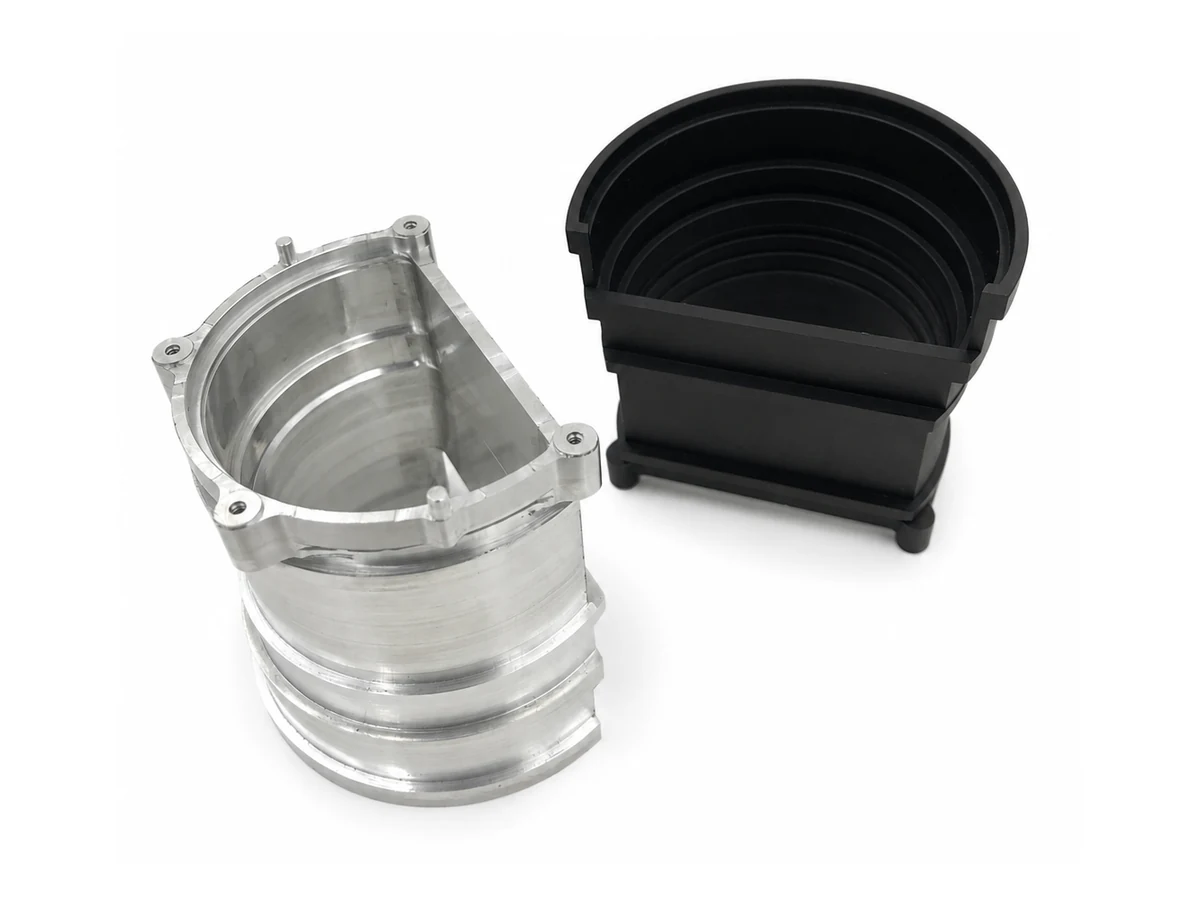
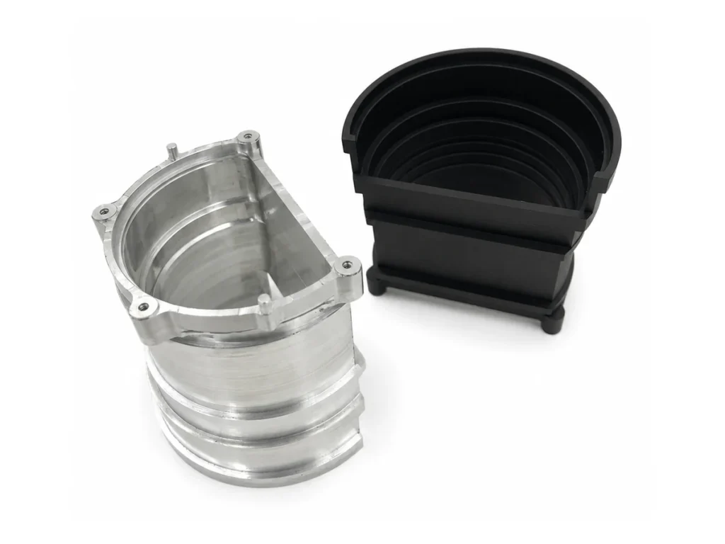
An aluminum lens barrel manufactured by turning and five axis machining
Our CNC machining service page includes a repeat-production optical lens barrel made from 6061-T6 aluminum using CNC turning and 5-axis CNC machining. The published photograph shows the same component design in an as-machined condition and with black anodizing. The project required control of the lens assembly features and the drawing-defined relationships between the bore, mounting interfaces and reference features.
The case identifies CMM inspection, bore gauges and thread gauges for the applicable characteristics. The manufacturing review connects the features that must locate together with the condition in which the finished part must meet its requirements.
Translate the optical layout into mechanical locating features
The optical designer may work with an optical axis and element spacing. The machinist needs physical surfaces and a datum system that express the relevant mechanical relationships. These might include a locating bore, a pilot diameter, a seating shoulder, a mounting flange or an attachment-hole pattern. Identify which features actually locate the component and which provide clearance.
A mechanical bore axis and the optical axis of an installed lens are not automatically identical. The lens itself has its own geometry and manufacturing variation, while its support and retention affect how it sits in the housing. The barrel drawing controls the mechanical contribution. It should not leave the supplier to infer an optical alignment requirement from a nominal cylindrical shape.
For example, a barrel may locate in the instrument through an outside pilot and a flange face, while an internal seat locates a lens group. In that arrangement, the relationship of the seat to those external interfaces matters. If the drawing instead references an unrelated cosmetic surface, machining and inspection can reproduce that reference without protecting the intended assembly. Our GD&T guide for CNC machining quotations explains how datum choices communicate these relationships.
Define the bore and seating shoulder as separate requirements
A lens barrel bore can contain several functional regions. One diameter may provide radial location, another may clear an optic or spacer, and a shoulder may establish an axial stop. A relief or lead-in has a different role again. Applying the same close tolerance to all internal surfaces can add work without controlling the actual contact. Edmund Optics’ overview of how an imaging lens is made identifies lens seats, bore gaps and spacers as mechanical details within a lens assembly.
Identify the intended contact region and the permitted clearance using the mating component specification. If the customer supplies a lens or lens group, its relevant dimensions and edge geometry still need to be understood. A generous entry chamfer can simplify insertion while reducing the usable locating length. A corner transition can interfere with a mating component before its face reaches the intended seat.
The seating shoulder needs its own location and orientation requirements. A correct bore size does not establish the shoulder’s axial position. Likewise, a shoulder can have an acceptable surface texture while being incorrectly oriented to the locating datum. Specify the relationship that matters rather than relying on the surface looking smooth. Flatness and parallelism in CNC machining describe different geometric questions and should not be used interchangeably.
For a barrel with several seats, define the axial distances from the chosen references. Identify whether a dimension controls one local shoulder, the spacing between two seats or the overall relationship to the mounting interface. The inspection plan should follow that same interpretation.
Maintain the datum relationship between turning and milling
CNC turning is useful for establishing rotational features such as accessible bores, outside diameters, steps and suitable threads. Milling adds openings, mounting details, flats and other features that do not share that rotational geometry. The published lens barrel used both turning and five-axis machining; another design may justify a different route.
The important issue is how the related features remain referenced when the component moves between operations. A turned bore and a later milled mounting face may each meet their local size limits while their relationship is wrong. The manufacturing plan must carry the relevant references into the later setup rather than treating each operation as a separate finished part.
Workholding also changes as material is removed. Openings and reduced wall sections can make a cylindrical component less rigid than the starting stock. Clamping must provide sufficient restraint without forcing the functional geometry into a temporary shape. Where the drawing requires the released part condition, a measurement taken only while the workpiece is constrained cannot settle final acceptance.
Five-axis access can help reach differently oriented features, but axis count does not establish dimensional conformity. Tool reach, support, reference transfer and the required measurement remain part-specific decisions. The process should be selected from the complete geometry, not from the word optical in the part description.
Specify retaining threads and assembly access
Threads in optical hardware can provide attachment, adjustment or retention. Those functions impose different requirements. A retaining ring that holds a lens against a shoulder does not perform the same task as a threaded interface used to adjust axial position. Explain the function and supply the complete thread specification rather than asking for a fine thread without defining it.
Include the thread standard, nominal size, pitch, tolerance class and effective engagement. Review the thread-end runout or relief, the lead-in and the space needed by the mating component. A ring can encounter the end of usable thread travel before it reaches the intended seating condition. A thread gauge result alone does not establish every axial clearance in that assembly.
Tool access for assembly matters as well. The customer should identify any spanner engagement, drive feature or restricted approach needed to install and remove a retainer. If trial assembly has a defined tightening torque or handling procedure, provide it. The manufacturer should not invent a retention load for an optical element. Our threaded hole machining guide provides related thread-callout and gauging considerations.
Plan black anodizing around the final interfaces
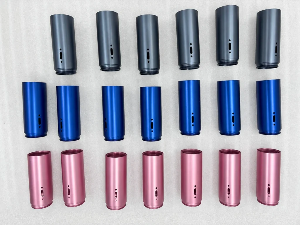
An aluminum lens barrel may be delivered as machined or with a specified finish. Black anodized lens barrels require the finishing plan to be connected to the drawing dimensions. Identify which bores, seats, threads and external locating surfaces are coated, which are masked if required, and which dimensions apply to the finished component.
Anodizing creates an oxide layer and can change the dimensions of a precision interface. Anoplate’s explanation of anodizing and dimensions describes the conversion of aluminum and its effect on the surface envelope. Pretreatment and the selected process also matter, so one generic coating allowance should not be applied to every bore and thread. The requirement should identify the finish specification and relevant thickness or performance controls. If masking or a later machining operation is proposed, its effect on corrosion protection, appearance and the functional surface needs approval.
A small change at one interface can alter a fit or the available retaining-thread engagement. Planning the finish before the bore is completed is therefore more useful than discovering an assembly problem after anodizing. Our aluminum anodizing guide discusses dimensional allowance and masking in greater detail.
Black color alone does not define an optical surface’s reflectance. Edmund Optics’ overview of light-absorbing coatings discusses wavelength and incidence angle as application variables. That supports specifying the required optical response rather than judging it from color alone. If the system requires a particular stray-light response or reflectance over a wavelength range, the customer needs a separate surface specification and acceptance method. The color photograph in this article is an appearance illustration, not an optical measurement.
Inspect the characteristics that establish the mechanical interfaces
Lens barrel inspection should begin with a feature list tied to the controlled drawing. Bore diameter, shoulder location, mounting-hole position and face orientation are separate characteristics. A measurement of one should not be reported as evidence for all of them.
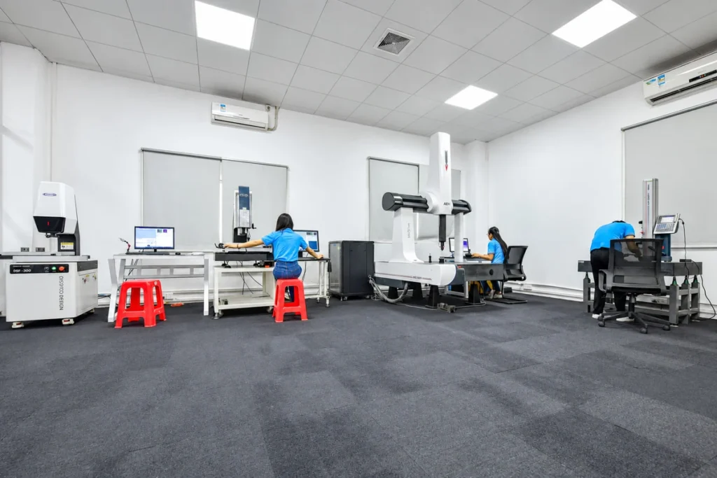
For the published case, bore gauges were used for applicable internal diameters, CMM inspection for the specified feature relationships, and thread gauges for the threaded features. These tools answer different questions. A diameter result does not automatically describe the entire bore form, and a passing thread gauge does not establish the position of the thread relative to a lens seat.
The CMM alignment must represent the datum requirements of the drawing. Measurement access, the selected locations and the part’s final condition also affect what the result establishes. If the customer needs measurements at several depths or a particular geometric control, include that scope before quotation. Do not assume that a report headed CMM inspection contains every surface or characteristic on the part.
Define the required records alongside the inspection plan. A dimensional report can identify nominal values, limits and applicable measured results. A material certificate addresses a different requirement, as does a finish record. Our CNC inspection report guide explains how to agree that documentation without treating one certificate as a substitute for the rest.
Use customer supplied components for an agreed trial assembly
Most of our lens barrel work is based on the customer’s drawing for manufacturing and dimensional inspection. When customers provide mating components, an agreed trial assembly can add information about physical fit, access and seating. Whether it is included depends on the project requirements and the components available.
Before the check, identify the mating component revision and what the trial is intended to establish. It might check whether a retainer can be installed, whether a component reaches its intended stop or whether an assembly tool has access. Also agree any restrictions on contact, handling or tightening. The presence of a supplied optic is not permission to perform an unspecified optical test or force an interference into place.
A successful trial with one supplied component does not demonstrate interchangeability across all permitted mating-part tolerances. Conversely, an assembly concern does not establish which part is responsible. Compare the observations with the drawing and the mating component definition before proposing a change.
Do not silently enlarge a bore, remove material from a seat or alter a retainer to make one sample fit. If a change is needed, evaluate the remaining material and its effect on related features, then obtain approval. Our guide to CNC prototype design changes explains the distinction between a feasible modification and a requirement that needs a newly machined part.
Keep mechanical verification separate from optical performance
A drawing-based inspection can establish the mechanical characteristics included in its scope. A trial assembly can show the agreed physical interactions with the supplied mating components. Neither automatically establishes focus, image quality, transmission, wavefront error or the complete instrument’s stray-light performance.
Where optical validation is required, the responsible party, test configuration and acceptance criteria need to be defined separately. The barrel manufacturer should receive the mechanical requirements that follow from that work, rather than be expected to derive them from an image-quality target. This distinction allows the dimensional evidence to support the customer’s system evaluation without overstating what has been checked.
Similarly, a visibly clean component is not evidence of a particle classification or a special environmental qualification. Specify cleaning, handling and packaging requirements when they are part of acceptance. Do not infer them from a black finish, a protective bag or the intended optical application.
Preserve the approved definition for repeat orders
Repeat lens barrel production needs the drawing, material condition and final finish to describe the same approved component. A change to a mating lens group, mounting interface or retainer may affect requirements even when the outside envelope looks unchanged. Identify the current revisions before repeating the machining order.
If a trial assembly uses a customer-supplied component, record its identity with the agreed result. That makes it possible to distinguish a repeat of the approved configuration from a later combination that has never been checked. The sample should support the controlled definition rather than become an undocumented alternative to the drawing.
For subsequent batches, agree which dimensions, finish characteristics and records remain part of acceptance. An earlier satisfactory component is useful background, but it does not remove the requirements for the next lot. Changes in the requested coating, inspection coverage or supplied mating parts should be reviewed before production resumes.
Provide the interface information needed for a useful quotation
An RFQ for custom machined lens barrels should communicate the assembly interfaces as clearly as the nominal model. Include the following where applicable:
- Current 3D geometry and a controlled 2D drawing with matching revisions.
- Material grade and condition, quantity and repeat-order expectations.
- Functional bores, seating shoulders, locating pilots and mounting datums.
- Required sizes, axial distances and geometric relationships.
- Complete thread specifications, engagement and assembly-tool access.
- Surface finish requirements, masking boundaries and the final dimensional condition.
- Edge requirements, appearance zones, cleaning and packaging needs.
- Inspection characteristics, report scope and any supplied mating components.
- The purpose and procedure for a requested mechanical trial assembly.
Where the mechanical definition is incomplete, identify the open interface before manufacturing release. A request to make the barrel fit a lens needs the relevant mating definition and acceptance scope. It should not require a supplier to guess a fit, a retaining load or an optical alignment tolerance.
Send the drawing and model to SAMSHION for a lens barrel machining review. Include any available mating-part information and distinguish dimensional inspection from a requested trial assembly or separate system test.
Questions about machining optical lens barrels
Can an acceptable bore diameter still leave a lens barrel assembly problem
Yes. Seat location, orientation, edge geometry, thread travel or the relationship to the mounting interfaces can matter independently of bore size. The drawing and inspection scope should identify the combination that controls the assembly.
Does every lens barrel need five axis machining
No. The published example used turning and five-axis machining, but the suitable route depends on the actual geometry and access. A different barrel may require fewer or different operations.
Is black anodizing proof of low reflectance
No. Color alone does not establish reflectance over the system’s wavelength range or angular conditions. Optical surface performance needs its own defined specification and acceptance evidence.
Does SAMSHION need a physical lens to machine the barrel
Most orders are manufactured and inspected from the customer’s drawing. Customers sometimes provide mating parts for an agreed trial assembly. A physical sample can support that check, but it does not remove the need for a clear mechanical specification.
Does a trial assembly replace dimensional inspection
No. It provides evidence for the agreed interactions with the supplied components. It does not establish every drawing requirement, all permitted mating-part combinations or the optical performance of the instrument.
Should lens barrel dimensions apply before or after anodizing
Identify the required acceptance condition explicitly. If the delivered finished interface controls assembly, its requirement must be addressed in the finishing and inspection plan. Separate pre-finish requirements can also be defined where the project needs them.