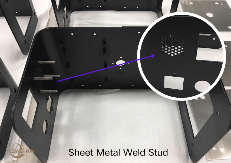
Stud welding is a fast way to attach threaded fasteners to thin metal without drilling a through-hole or placing a nut on the opposite side. In custom sheet metal fabrication, capacitor-discharge (CD) stud welding is especially useful for enclosures, brackets, panels and equipment housings because the weld cycle is very short. However, a strong stud does not automatically guarantee an acceptable cosmetic surface.
Marks around a stud can originate in three different systems: the weld itself, deformation of the sheet, or the subsequent coating process. Excessive flash, a weak cold weld, a tilted stud, backside read-through and powder-coat pinholes may look related, but they require different corrective actions. This guide explains how to diagnose weld stud surface defects, prevent them before production and verify the result before finishing.
Key Takeaways
- Separate weld quality, sheet appearance and coating quality before choosing a corrective action.
- Use equipment-manufacturer settings only as a starting point; validate the process on the actual sheet grade, thickness, stud and finish.
- A visual check is necessary but does not replace mechanical testing when the joint carries a specified load.
- Control cosmetic witness marks through DFM, fixturing and a qualified energy window before the production batch begins.
- Treat powder-coat bubbles or pinholes as a combined welding, cleaning, pretreatment and curing problem – not automatically as a bad weld.
What Counts as a Weld Stud Surface Defect?
A weld stud surface defect is any weld-side, sheet-side or finish-related condition that falls outside the drawing, approved cosmetic standard or validated welding procedure. Some applications permit a small, consistent witness mark on a hidden face. A consumer-facing enclosure may require no visible read-through under directional light. Acceptance therefore starts with the part specification, not with a universal “perfect surface” rule.
Weld Side, Cosmetic Face and Coating Layer
The weld side is the face where the stud is attached. Inspect it for flash, spatter, incomplete fusion, tilt and local burning. The opposite or cosmetic face must be checked for a circular witness mark, pimple, depression, oil-canning or discoloration. After powder coating, painting, plating or anodizing, inspect a third layer of evidence: pinholes, blisters, craters, color variation and loss of adhesion. Recording the defect by face and process stage prevents a coating symptom from being incorrectly blamed on welding energy.
Common Weld Stud Surface Defects and What They Indicate
1. Excessive Flash and Weld Spatter
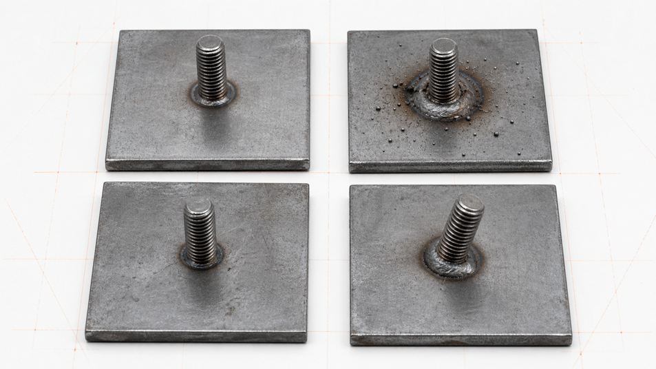
A small, uniform flash around a CD stud can be normal. Heavy flash, scattered metal droplets or a large irregular fusion ring indicates an overheated or unstable weld. Possible contributors include excessive voltage or capacitance, insufficient spring pressure, incorrect stud-tip geometry, poor contact, contamination or an unsuitable stud-to-sheet combination. A “too hot” weld is not necessarily stronger; excessive melting can weaken the joint and damage the sheet.
2. Little or No Visible Flash
A cold weld may show little flash and may detach during a bend, torque or pull test. Causes include insufficient stored energy, excessive spring pressure, poor grounding, an incorrect gap or protrusion, a damaged ignition tip, or contamination that interrupted current flow. Do not accept a stud only because it remains upright after welding.
3. One-Sided Flash or a Tilted Stud
Asymmetric flash usually means that the gun was not perpendicular, the foot did not sit flat, the stud was loose in the collet, the panel moved, or current flow was uneven. The stud may pass a casual visual check but create assembly misalignment or a weak segment around the weld circumference.
4. Backside Indentation, Pimples and Read-Through
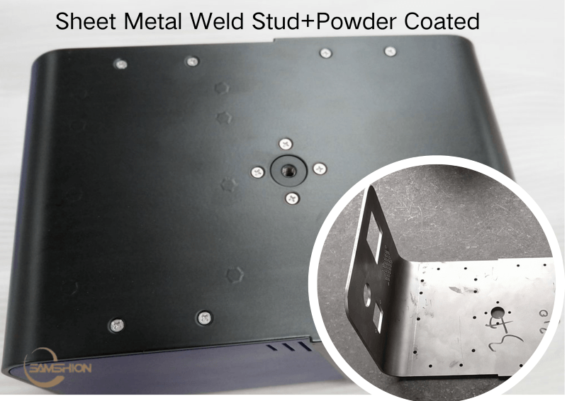
Thin sheet can show the weld location on the opposite face even when the stud is securely attached. Excessive energy, a large stud base, low sheet stiffness, poor backing support, residual forming stress or welding too close to an edge or bend can make the mark more visible. The final powder coat may amplify the defect because gloss and directional lighting reveal slight waviness.
5. Burn-Through, Craters and Local Warping
Burn-through is a severe mismatch between the energy delivered and the thermal capacity of the sheet. Local craters, thinning or oil-canning can also occur before complete penetration. Stop production when these symptoms appear. Reconfirm sheet thickness and grade, stud size, energy, spring pressure, fixturing, part temperature and ground placement before continuing.
6. Pinholes, Bubbles and Craters After Powder Coating
A coating defect near a weld may be caused by oil, cleaning residue, oxide, trapped moisture, weld porosity or gas escaping from seams and recesses during cure. Galvanized surfaces and porous substrates can also outgas. The Powder Coating Institute defines gassing as air or gas escaping from below a coating and producing blisters, bubbles or small holes. The correct investigation therefore includes the weld, pretreatment, drying, powder application and cure schedule.
7. Heat Tint and Surface Contamination
Discoloration may signal local oxidation, contamination or excessive heat. Stainless steel and aluminum need material-specific post-weld treatment; aggressive grinding can replace a small heat mark with deep scratches or a distorted cosmetic face. Define the required finish before selecting mechanical cleaning, passivation, brushing, polishing, powder coating or anodizing.
Root Causes of Weld Stud Surface Defects
Surface Condition and Electrical Contact
Oil, drawing lubricant, oxide, rust, scale, paint, powder coating, moisture and loose debris can interrupt arc initiation or create gas and inclusions. The stud tip and weld area should be prepared according to the equipment and fastener manufacturer’s instructions. Ground clamps must contact clean metal and be positioned to avoid an unbalanced current path. Do not improvise a cleaning method that embeds abrasive residue or changes a visible grain finish without testing it first.
Incorrect Energy and Mechanical Settings
CD weld energy is influenced by charging voltage and capacitance, while the mechanical result is also affected by spring pressure, plunge, stud protrusion, initial gap and tip length. Nelson’s operating guidance describes higher voltage or capacitance as producing a hotter weld and higher spring pressure as producing a colder weld. The relationships are useful for troubleshooting, but the final setting must come from trial welds and acceptance tests on the production material.
Gun Alignment, Collet Condition and Fixturing
A perpendicular gun, the correct collet and stop, stable foot contact, secure cables and repeatable panel support are essential. A worn or incorrect collet can let the stud tilt; flexible panels can deflect when the gun is pressed; poor fixturing can allow thermal movement. Inspect components based on condition and the manufacturer’s maintenance guidance rather than an arbitrary calendar interval.
Part Design and Stud Selection
A stud that is appropriate for one panel may create read-through on a thinner sheet. Review the stud base diameter, thread size, required load, sheet thickness, distance from bends and edges, access for the gun, visible-face class and available backing support. The selected stud should be intended for the welding process and material, not a conventional bolt substituted into the weld gun.
Confirm weldability, corrosion behavior and finish compatibility using the sheet metal materials guide and the stud supplier’s data before releasing production.
Material and Finish Compatibility
Like-to-like material combinations are often the most straightforward, but “the materials must always be identical” is too broad. Stud manufacturers offer mild-steel, stainless-steel and aluminum products for defined applications. Dissimilar or coated combinations require documented compatibility and qualification because electrical resistance, melting behavior, corrosion potential and coating condition all affect the result.
Finishing Sequence and Handling
Studs are normally welded before powder coating or painting so the weld current reaches clean metal. After welding, remove loose spatter and residues without thinning or gouging the panel. Protect threads during pretreatment and coating, dry seams completely and inspect the part before it enters the finishing line. For anodized aluminum, recognize that the weld zone and material condition can produce visible color or texture variation.
Symptom-Cause-Verification-Correction Table
Visible Symptom | Likely Causes | How to Confirm | Corrective Direction |
Heavy flash or spatter | Excessive energy, low spring pressure, contamination or unstable contact | Compare flash around 360 degrees; review settings and test coupon | Reduce energy in controlled steps; verify pressure, tip, contact and cleanliness |
Little or no flash; weak stud | Low energy, excessive pressure, poor ground or incorrect gap/protrusion | Perform approved bend/torque/pull test; check cables and setup | Raise energy within the qualified window; correct setup and grounding |
One-sided flash or tilted stud | Gun angle, loose collet, uneven foot contact or panel movement | Check perpendicularity and full flash circumference | Correct gun/fixture alignment; inspect collet, stop and foot |
Backside ring, pimple or dent | Excessive heat/force, thin sheet, large stud base or poor support | Inspect under controlled light and measure flatness | Optimize energy/pressure; add backing support; revise stud or panel design |
Burn-through or crater | Severe energy-to-thickness mismatch | Section a test coupon if necessary and reconfirm material thickness | Stop production; requalify parameters and stud selection |
Powder-coat pinholes or bubbles | Contamination, moisture, trapped gas, porous/galvanized surface or cure issue | Trace defect from pre-cleaning through cure; compare uncoated control parts | Improve cleaning/drying; review pretreatment, outgassing and cure schedule |
Heat tint or scratches | Oxidation or aggressive post-weld grinding | Compare with approved finish sample and inspect grain/flatness | Use material-specific finishing and controlled light abrasion |
A Practical Workflow for Preventing Stud Welding Defects
- Define the functional and cosmetic requirements. Mark the stud side and visible face on the drawing. Specify allowed witness marks, flatness, perpendicularity, thread protection and the final finish.
- Lock the material stack. Confirm sheet grade and thickness, stud material and base diameter, incoming coating or plating, and the intended powder coat, paint, plating, passivation or anodizing process.
- Establish a process window on representative coupons. Use the equipment manufacturer’s recommendation as a starting point, then make trial welds on the same material and thickness. Evaluate hot, cold and centered settings without jumping directly into the production batch.
- Standardize preparation and setup. Clean the weld zone and stud tip, verify the ground path, install the correct collet and stop, set protrusion or gap, hold the gun perpendicular and support the sheet.
- Control production. Record the approved parameters, check the first-off part, monitor flash and alignment, sample mechanical performance at the defined frequency and stop when the appearance changes.
- Prepare the assembly for finishing. Remove loose spatter with controlled tools, avoid deep grinding, clean and dry the part, protect threads and inspect the cosmetic face before coating hides the root evidence.
- Verify the finished surface. Inspect under agreed lighting and viewing distance, check coating around studs and seams, and retain approved samples or photographs for repeat orders.
For a wider view of how these controls fit into cutting, bending, welding, finishing and inspection, review our sheet metal workshop and production process.
Material and Surface-Finish Considerations
Carbon and Mild Steel
Low-carbon steel CD studs and sheet are common for powder-coated enclosures. Remove oils and loose oxide, validate any zinc or other coating in the weld zone, and control post-weld cleaning so the powder pretreatment has a uniform surface.
Stainless Steel
Use compatible stainless studs and a qualified procedure. Prevent iron contamination from carbon-steel tools and select the required post-weld treatment, such as cleaning, brushing, passivation or electropolishing – according to the drawing and service environment.
Aluminum
Aluminum requires equipment, studs and settings intended for aluminum. Its oxide layer and high thermal conductivity affect welding behavior. If the part will be anodized, approve a visual sample because weld zones and alloy differences can create color or texture variation. Powder coating may be a more forgiving cosmetic option for some assemblies.
Galvanized or Pre-Coated Sheet
Some CD systems and studs are used on coated or galvanized material, but the combination must be validated. Coatings can change contact resistance, generate fumes, contaminate the weld zone and contribute to powder-coat outgassing. Follow ventilation and safety requirements and never assume that a setting developed on bare steel will transfer unchanged.
Inspection and Acceptance
A production control plan should match the risk of the part. A cosmetic cover and a load-bearing safety component do not need the same test frequency, but both need defined acceptance criteria.
- Visual inspection: flash consistency, spatter, burn-through, tilt, backside marking and contamination.
- Dimensional inspection: stud location, perpendicularity, thread condition, panel flatness and assembly fit.
- Mechanical verification: bend, torque, pull or other tests selected for the fastener and application.
- Process verification: recorded settings, first-off approval, equipment condition and sample frequency.
- Finish inspection: coating adhesion and appearance around the stud, thread masking and agreed cosmetic standard.
ISO 14555:2025 addresses stud-welding quality requirements, procedure specification and qualification, operator qualification and production-weld testing. Apply the parts that are relevant to the contract and application. Samshion’s quality assurance system provides the broader framework for documented process and inspection control.
When an Alternative Fastener Is the Better Choice
Stud welding is not automatically the best choice for every thin or highly cosmetic panel. During DFM, compare the load, visible-face requirement, access, volume, finish and serviceability with alternative joining methods.
Self-clinching studs or nuts: Useful when controlled press access is available and a small opposite-face witness mark is acceptable.
Rivet nuts: Suitable for lower-volume assemblies and serviceable threads, but require a hole and may project on the opposite side.
Projection-welded fasteners: Effective for repeat production with appropriate tooling and access, but require a qualified resistance-welding process.
Through-bolts or captive hardware: Simple and replaceable, but need opposite-side access and may conflict with the cosmetic design.
Adhesive-bonded or mechanically retained mounts: Useful for selected low-load cosmetic applications after environmental and durability validation.
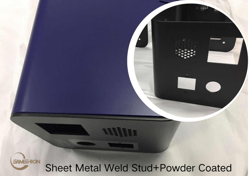
How Samshion Approaches Weld Studs Before Surface Finishing
At Samshion, the practical starting point is a DFM review of the sheet thickness, stud specification, load, access, visible-face requirement and final finish. Representative trial parts are used to confirm the process window before the batch proceeds. In-process checks focus on alignment, flash condition and panel distortion, followed by controlled cleaning and finish inspection.
The required verification should be defined on the drawing or quotation. Depending on the application, it can include first-article dimensional inspection, visual acceptance samples and mechanical sample testing. Clear requirements at the quotation stage reduce rework and prevent a functional weld from becoming a cosmetic rejection after powder coating.
If your enclosure or panel includes welded studs, contact our manufacturing engineers with the STEP or DXF file, material and thickness, stud specification, quantity, load requirement and surface finish. We can review the design and identify cosmetic or process risks before production.
Frequently Asked Questions
Can capacitor-discharge stud welding be completely invisible on the opposite face?
Not in every material and thickness. CD welding minimizes heat input, but thin or highly reflective panels may still show a small witness mark. The result depends on sheet stiffness, stud size, energy, spring pressure, support, residual stress and finish. Approve a representative cosmetic sample when the opposite face is visible.
Why do bubbles or pinholes appear around studs after powder coating?
Possible causes include oil, moisture, cleaning residue, oxide, trapped gas in the weld or seams, a galvanized or porous substrate, and incorrect pretreatment or cure conditions. Compare the uncoated part, trace the defect through the finishing line and avoid assuming that every bubble indicates a weak weld.
Can studs be welded through paint or powder coating?
The normal production sequence is to weld on suitably prepared metal before painting or powder coating. Welding through an existing finish can disrupt electrical contact, contaminate the joint, damage the coating and create fumes. Any coated-sheet application must follow a validated system and the manufacturer’s instructions.
Do the stud and sheet have to be the same material?
Not as an absolute rule, but compatible materials and purpose-made studs are essential. Like-to-like combinations are often the simplest. Dissimilar or coated combinations should be approved using supplier data, corrosion considerations and representative weld tests.
How should a stud weld be tested?
Start with visual and dimensional inspection, then use the bend, torque, pull or other mechanical test specified for the stud and application. The drawing, qualified procedure and applicable standard should define the method, sample frequency and acceptance criteria.
How can backside marking on thin sheet be reduced?
Use the smallest suitable stud and weld base, validate the lowest stable energy window, optimize spring pressure and protrusion or gap, support the panel, maintain gun perpendicularity and avoid placing studs too close to bends or edges. If the cosmetic requirement remains too strict, evaluate a self-clinching or mechanical alternative.
Conclusion
Reliable stud welding is not achieved by one voltage setting or one cleaning step. It comes from matching the stud, sheet, equipment setup, cosmetic requirement and finishing route, then confirming the combination on representative parts. The most effective way to prevent weld stud surface defects is to separate weld quality from sheet deformation and coating quality, control each stage and document what an acceptable result looks like before production.