Insert injection molding is a specialized variant of traditional injection molding that integrates pre-manufactured inserts into plastic parts in a single molding cycle. Unlike standard plastic molding that produces pure plastic components, this advanced manufacturing technology encapsulates metal, ceramic, or rigid plastic inserts with molten thermoplastic, creating high-strength, multi-material hybrid parts.
The Applications of Insert Injection Molding
Insert Injection molding widely adopted in automotive, electronics, medical, and industrial equipment industries, insert injection molding solves the limitations of single-material parts, eliminates secondary assembly processes, and balances structural strength, dimensional accuracy, and production efficiency.
What Is Insert Injection Molding?
Basic Definition of Insert Injection Molding
Insert injection molding is a precision manufacturing process that fixes prefabricated functional inserts in a customized mold cavity in advance, then injects molten plastic around the inserts. After cooling and solidification, the plastic and inserts form a mechanically integrated single component without additional bonding, welding, or assembly procedures.
Insert Injection Molding = One-Shot Composite Forming?
The core logic lies in one-shot composite forming. The pre-placed inserts are precisely positioned and fixed in the mold; high-pressure molten plastic flows and wraps the insert surface, fills the mold cavity, and forms a tight mechanical combination through plastic shrinkage and insert surface friction/embedding structure after cooling. This process realizes the organic combination of the toughness, lightweight of plastics and the hardness, conductivity, and wear resistance of insert materials.
Common Types of Inserts
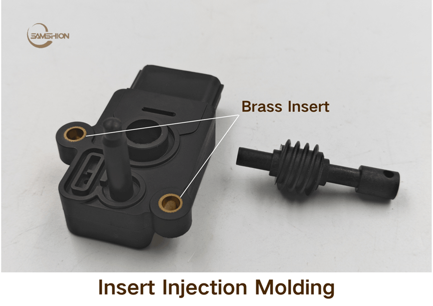
- Metal inserts: Threaded copper/brass nuts, stainless steel pins, conductive terminals, metal shafts (most widely used)
- Non-metal inserts: Ceramic wear-resistant parts, rigid plastic structural parts, glass components
- Functional inserts: Electronic connectors, sensor components, magnetic parts
Step-by-Step Insert Injection Molding Process
Different from traditional injection molding, insert molding adds precise insert positioning and pre-treatment links. The complete standardized process is divided into 6 core steps:
Insert Preparation & Pre-treatment
Inserts are inspected for dimensional accuracy, surface cleanliness, and structural integrity. Remove oil stains, burrs, and impurities to avoid poor bonding. Large metal inserts need preheating (150–200°C) to eliminate temperature difference and prevent plastic cooling defects.
Mold Loading & Insert Positioning
Manually or automatically place qualified inserts into the preset fixed position of the mold cavity, ensuring no offset, shaking, or displacement. The mold is then closed and locked tightly.
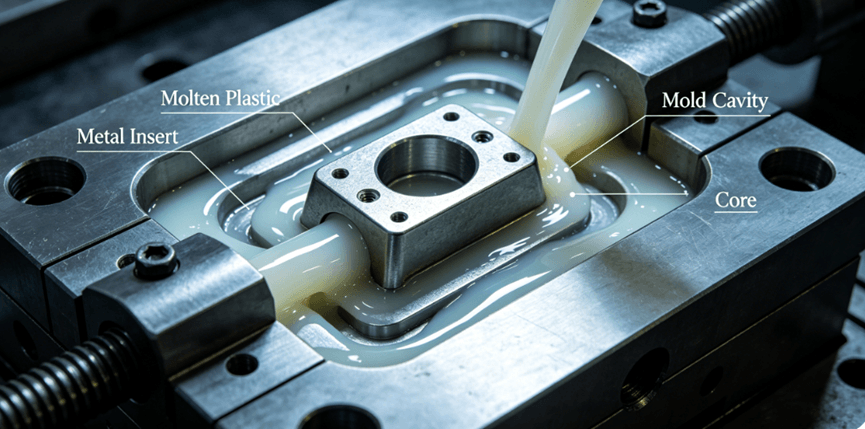
Plastic Melting & Injection
Thermoplastic raw materials are heated and melted in the injection molding machine barrel. The molten plastic is injected into the mold cavity at high pressure and speed, fully wrapping and covering the pre-placed inserts.
Cooling & Solidification
Keep the mold closed for a certain cooling time to make the molten plastic fully solidify and closely bond with the insert, forming a stable integrated structure.
Mold Opening & Ejection
After cooling and shaping, the mold is opened, and the integrated plastic-insert part is ejected through the ejection system.
Post-processing & Inspection
Remove runner waste, check for insert deviation, plastic bubbles, insufficient filling, and other defects, and conduct size and performance sampling tests.
Key Advantages of Insert Injection Molding
Simplify Production & Reduce Costs
It integrates molding and assembly into one process, eliminating secondary assembly, screw fixing, glue bonding, and other processes. It reduces the number of parts, saves labor and assembly costs, and shortens the overall production cycle, which is especially suitable for mass production.
Improve Part Structural Performance
The integrated forming structure avoids loose assembly and falling off problems. Metal inserts effectively enhance the local strength, wear resistance, compression resistance, and threaded connection stability of plastic parts, solving the defect of easy cracking and poor load-bearing capacity of pure plastic structural parts.
Enrich Product Functional Design
It realizes the composite integration of multiple materials and multiple functions. It can endow plastic parts with conductivity, magnetism, high-temperature resistance, and wear resistance that single plastic materials do not have, supporting the design of complex precision functional parts.
Enhance Dimensional Stability
Precise mold positioning and one-shot forming effectively control part tolerance, avoid assembly errors caused by manual operation, and significantly improve the overall dimensional accuracy and consistency of parts.
Material Selection Guidelines (Inserts & Plastics)
Common Insert Materials & Characteristics
Brass/Copper
Good conductivity, ductility, and thread processing performance, suitable for electronic conductive terminals and threaded connection inserts
Stainless Steel
High hardness, corrosion resistance, and wear resistance, suitable for structural support and wear-resistant functional inserts
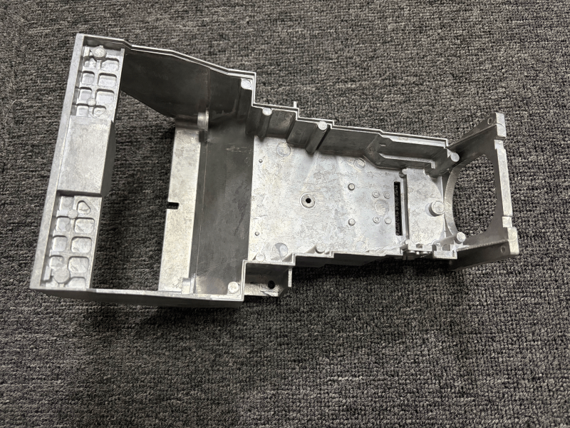
Aluminum Alloy
Light weight and high strength, suitable for lightweight structural parts in automotive and aerospace fields
Ceramic
High temperature resistance and insulation, suitable for high-temperature and electrical insulation scenarios
Requirements for Inserts Used in Insert Injection Molding
Clean & oil-free
Inserts must be fully degreased, without oil, dust, oxidation layers or release agent residue. Contamination will cause poor adhesion, bubbling or separation between plastic and inserts.
Appropriate surface texture for mechanical lock
Add knurls, undercuts, grooves, ribs or serrations on insert outer surfaces. These structures create mechanical interlock to stop inserts from spinning, shifting or pulling out after molding.
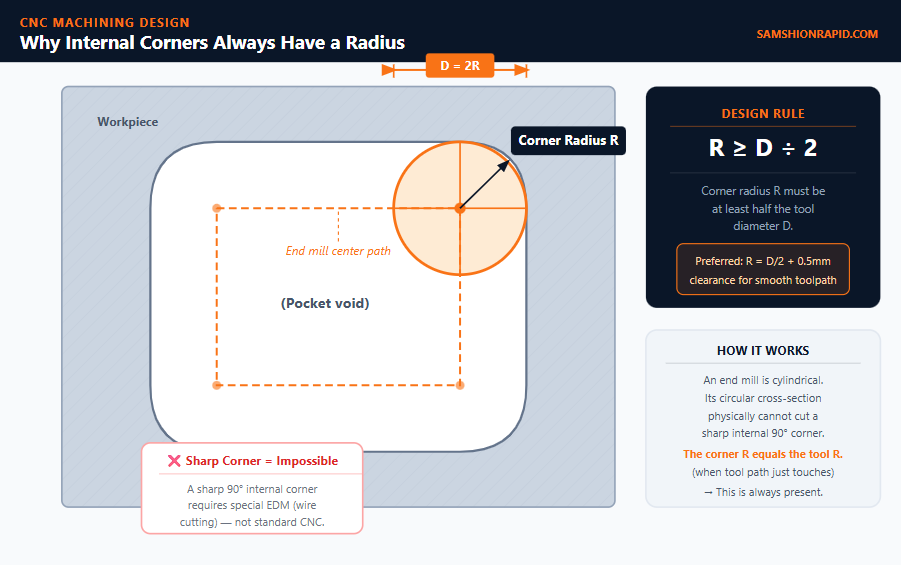
Smooth rounded corners
Sharp edges and sharp corners are forbidden. Fillets shall be designed to avoid stress concentration and plastic cracking during cooling shrinkage.
Inserts’ Material Compatibility
Matching coefficient of thermal expansion (CTE)
The thermal expansion rate of insert material shall be as close as possible to the molded plastic. Large CTE difference brings huge residual stress and plastic cracking during cooling.
Heat resistance
Inserts must withstand plastic melt temperature and mold temperature without softening, melting or oxidation discoloration.
Chemical compatibility
No chemical reaction between inserts and molten plastic. Avoid corrosion or gas generation at high temperature.
Matching Plastic Materials
Commonly used engineering plastics include ABS, PC, PA66, PBT, TPU, and POM. The core selection principle is matching the thermal expansion coefficient of inserts and plastics to avoid cracking, warping, and debonding caused by inconsistent thermal expansion and contraction during cooling. For high-strength and high-temperature resistant scenarios, modified reinforced plastics (glass fiber reinforced PA/PC) are preferred.
Main Industrial Applications
Consumer Electronics
Widely used in mobile phone structural parts, connector terminals, switch buttons, and charging port components. It ensures the conductive stability and structural firmness of electronic parts while realizing lightweight and miniaturized design.
Automotive Industry
Applied to automotive interior parts, sensor housings, wiring harness connectors, and engine small structural parts. It meets the requirements of automotive parts for high temperature resistance, vibration resistance, and structural stability.
Medical Equipment
Used for precision medical instrument connectors, surgical tool accessories, and detection component shells. It features high precision, good biocompatibility, and no loose assembly residues.
Industrial & Household Appliances
Suitable for electrical switch parts, hardware fastening components, household appliance structural supports, and mechanical equipment small precision parts, adapting to long-term stable working conditions.
Insert Injection Molding ‘s Critical Design Guidelines & Best Practices
Insert Structural Design
Design anti-slip structures such as knurls, grooves, and steps on the insert surface to enhance mechanical bonding force with plastics and prevent rotation and falling off. Avoid sharp corners on inserts to prevent piercing plastic layers and causing cracking.
Insert Injection Mold Design Key Points
Set reliable insert positioning and fixing mechanisms to avoid displacement during high-pressure injection. Optimize the gating system to ensure uniform plastic flow and prevent air trapping and insufficient filling around inserts. Design a reasonable cooling system to ensure balanced cooling of plastic and inserts.
Process of Injection molding Parameter Control
Reasonably control injection pressure, speed, and mold temperature. Excessively high pressure will cause insert deviation, while excessively low pressure will lead to poor bonding. Match preheating temperature and cooling time according to insert size and material characteristics.
Common Defects & Troubleshooting Solutions of Insert Injection Molding
| Common Defects | Root Causes | Solutions |
| Insert displacement/offset | Unreliable insert positioning, excessive injection pressure | Optimize mold fixing structure, adjust injection pressure and speed |
| Poor bonding & loose inserts | Dirty insert surface, no anti-slip structure, unreasonable cooling | Clean inserts, add knurl/groove structures, optimize cooling parameters |
| Plastic cracking around inserts | Mismatched thermal expansion coefficient, sharp insert corners, residual stress | Optimize material matching, fillet insert corners, eliminate molding residual stress |
| Air bubbles & insufficient filling | Unreasonable gating design, poor mold exhaust | Optimize runner position, increase exhaust slots, adjust injection parameters |
Insert Injection Molding vs Overmolding: Core Differences
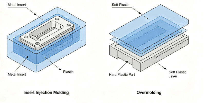
Many people confuse insert molding with over molding. The core difference lies in molding logic and application scenarios:
Insert Molding
Embed rigid functional inserts (metal/ceramic) into plastic, focus on enhancing structural strength and single-point functional performance, realize rigid composite integration.
Overmolding
Mold soft plastic (TPU/TPE) on the surface of hard plastic parts, focus on improving hand feel, anti-slip, shockproof and aesthetic performance, mostly soft and hard composite.
FAQ
Is insert injection molding suitable for small-batch production?
Insert molding requires customized molds with insert positioning structures, so it is more cost-effective for medium and large-batch production. For small-batch customized parts, manual assembly may be more economical.
How to ensure the bonding firmness of inserts and plastics?
Three core measures: add anti-slip structures on insert surfaces, strictly clean insert pre-treatment, and match reasonable molding pressure and cooling parameters to ensure tight mechanical embedding.
What is the tolerance range of insert molding parts?
Precision insert molding can control the tolerance within ±0.05mm, which meets the precision requirements of most electronic and automotive precision parts.
Samshion Could help you out for mastering its process rules, material matching and design specifications
Insert injection molding is an indispensable precision composite molding technology in modern manufacturing. It breaks through the performance limitations of single-material parts, realizes the perfect combination of different material advantages, and has irreplaceable value in improving product performance, simplifying production processes, and controlling manufacturing costs.