Introduction
The price of a CNC-machined prototype is not determined by cutting time alone. Before the first acceptable part leaves the machine, an engineering team may need to review the model and drawing, plan the machining sequence, program toolpaths, select or manufacture workholding, establish work offsets, prove out the program and verify the first part. Much of this work is required whether the order contains one part or one hundred.
Fixturing and setup therefore have a large influence on prototype and low-volume pricing. They also affect dimensional repeatability, surface finish, tool access, operator safety and the risk of distortion. The lowest-cost fixture is not automatically the simplest fixture, and a sophisticated fixture is not automatically economical for a small order.
This guide explains what CNC fixturing and setup include, how manufacturers choose workholding for different quantities, and what product designers can do to reduce non-recurring work without weakening process control. For a broader overview of the manufacturing process, start with our CNC machining services.
What CNC Fixturing and Setup Actually Include
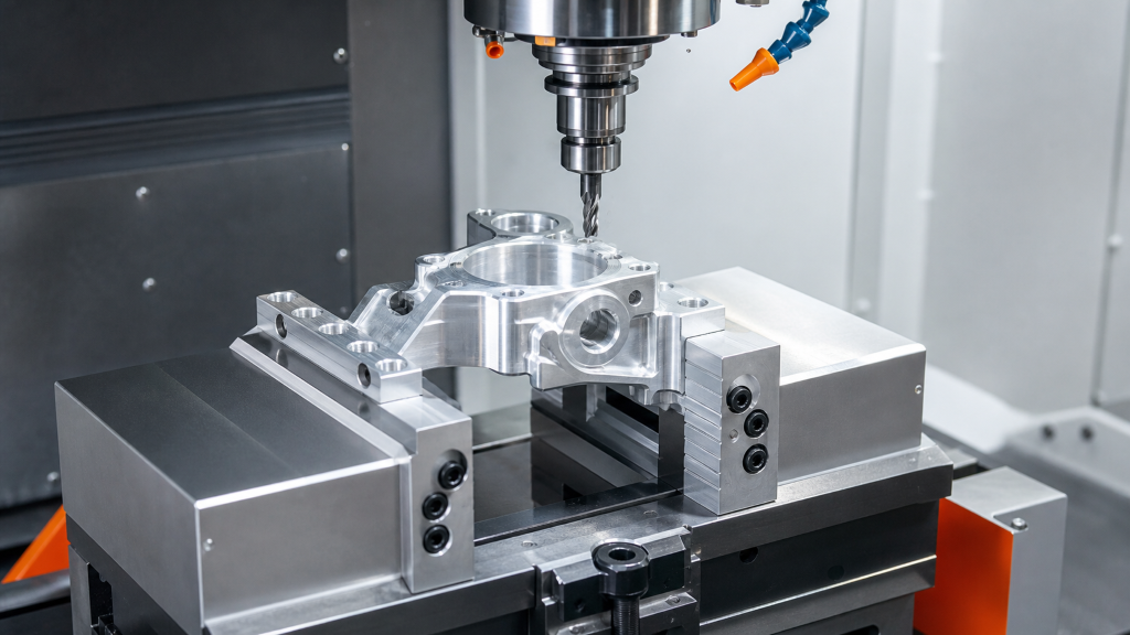
A fixture is a workholding system that establishes and maintains the position of a workpiece during manufacturing. It may be as simple as a standard vise with parallels or as specialized as a multi-station hydraulic fixture. A setup is the complete manufacturing arrangement for one machining orientation, including the machine, workholding, work coordinate system, tools, program and verification plan.
The terms are related but not interchangeable. One fixture can support several operations in a single setup. A part may also require multiple setups, each with different locating surfaces, clamps and work offsets. Turning the part over, moving it to another machine or changing the datum reference normally creates another setup that must be planned and verified.
Typical setup work includes:
- Reviewing CAD, drawings, datums, tolerances, material and quantity.
- Selecting a vise, chuck, collet, soft jaw, fixture plate or dedicated fixture.
- Defining the machining sequence and accessible features for each orientation.
- Programming and simulating toolpaths with the workholding represented where necessary.
- Preparing tools and measuring tool lengths or diameters.
- Loading the workpiece, setting work coordinates and confirming clamp clearance.
- Running a controlled prove-out and checking the first acceptable part.
- Recording offsets, inspection results and instructions for repeat production.
Autodesk’s official workholding example shows why the vise or fixture should be represented in the manufacturing model: it helps the CAM system account for objects that the cutting tool must avoid. See adding workholding equipment to a manufacturing model.
Why the First Acceptable Part Carries More Work
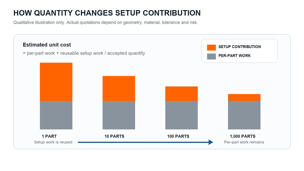
The first part in a new job absorbs work that later parts can reuse. CAM programming, fixture preparation, tool selection and first-off verification do not normally increase in direct proportion to quantity. This is why unit cost often decreases as the same verified setup produces more acceptable parts.
That does not mean every setup has the same fixed cost or that quantity is the only cost driver. A simple plate held in a standard vise may require little preparation. A thin casting with irregular datums may need a custom nest, adjustable supports and a controlled clamping sequence. Tight positional tolerances between opposite faces can require probing, datum transfer and additional inspection. Each quotation must reflect the actual geometry, material, tolerances, documentation and production risk.
The related prototype machining cost analysis explains how setup, cycle time, material, finishing and inspection combine in a quote.
Locating and Clamping Are Different Functions
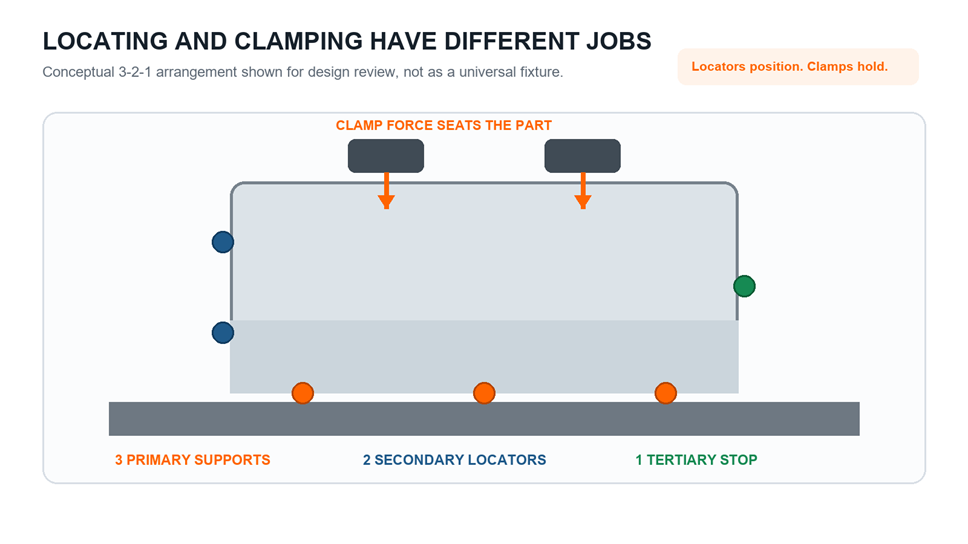
Good fixture design begins by separating two jobs. Locators establish the workpiece position. Clamps push and hold the workpiece against those locators. A clamp should not be expected to create a precise reference by itself, and added clamping force cannot correct an unstable locating scheme.
Carr Lane’s official fixture design principles describe locating and clamping as the critical functions of a workholder and explain that a locator’s primary purpose is to reference the workpiece and support repeatability.
Establish a Stable Datum Structure
A common conceptual method uses three contacts on a primary plane, two on a secondary plane and one on a tertiary plane. This 3-2-1 arrangement can constrain the workpiece’s six degrees of freedom without redundant location. Real parts may use planes, holes, pins, bores, V features or profiles instead, but the purpose remains the same: establish a repeatable relationship between the workpiece and the machine coordinate system.
Datum selection should follow part function and drawing requirements. If machining features are controlled from datum A, B and C, the workholding and inspection plan should make those relationships practical. ASME Y14.5 provides standardized rules for communicating dimensions, datums and geometric tolerances.
Direct Clamping Force Toward Support
Clamps should seat the part against locators and supports. Placing a clamp over an unsupported thin wall can bend the workpiece during machining. The part may appear correct while clamped and move out of tolerance after release. More force is not always better. The required force depends on cutting loads, contact friction, support location, material strength and safety margin.
Resist Cutting Forces Without Blocking the Tool
The fixture must provide a short, rigid load path from the cutter through the workpiece into supports and the machine table. Clamps and fixture bodies must also stay clear of the tool, holder, spindle, probing moves and chip flow. Tool access can be included in CAM simulation, but the physical setup still needs a controlled prove-out.
Distinguish Repeatability From Absolute Accuracy
A fixture can load parts very consistently yet locate them at the wrong coordinate. Conversely, a carefully indicated first part may not repeat if chips collect on a locator or the loading method varies. Process control requires both an accurate relationship to the work coordinate system and repeatable seating from part to part.
Workholding Options by Quantity and Geometry
Standard Workholding
Vises, chucks, collets, parallels, step blocks and fixture plates are flexible and require little dedicated tooling. They are often economical for simple prototypes, prismatic stock and parts with accessible gripping surfaces. Standard workholding may still require preparation, indication and safe gripping stock.
Semi-Custom Workholding
Machined soft jaws, bored jaws, profile nests and simple subplates adapt standard hardware to a specific part. They can improve repeatability and tool access without the design effort of a fully dedicated fixture. Soft jaws are especially useful when a second operation must locate from geometry produced in the first operation.
Modular and Reconfigurable Fixtures
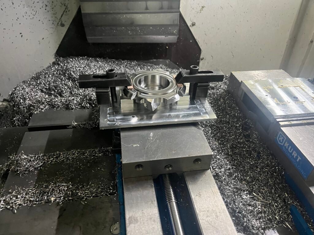
Modular plates, locating pins, supports and clamps can be rearranged for different parts. This approach can reduce fixture lead time and spread reusable hardware across multiple jobs. It is valuable for low-volume families of parts, although setup documentation and collision checking remain necessary.
Dedicated Production Fixtures
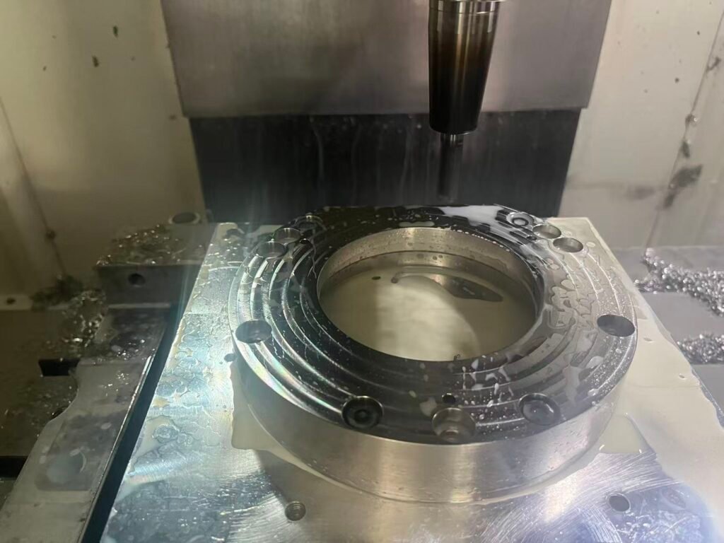
A dedicated fixture may combine multiple stations, quick loading, pneumatic or hydraulic clamping, part-present sensing and defined poka-yoke features. Its engineering and build cost can be justified when repeat quantity, cycle-time reduction, operator consistency or process capability provides enough value. It may not be the right choice for an evolving prototype design.
Vacuum, Magnetic and Adhesive Workholding
These methods can be useful for selected geometries. Vacuum workholding can support thin flat parts but requires enough sealed area and a suitable cutting strategy. Magnetic workholding applies only to compatible ferromagnetic materials. Adhesive or sacrificial techniques can improve access but add preparation and release considerations. None is a universal substitute for mechanical support.
How Setup Count Changes Cost and Risk
Each setup introduces loading time, another coordinate relationship and another opportunity for datum-transfer error. A three-axis part may require separate orientations for top, bottom and side features. The planner must decide which features belong together, where to leave gripping stock and how to preserve relationships across operations.
Five-axis positioning can expose more faces in one setup and allow shorter tools. It can reduce re-clamping and improve feature relationships on suitable parts. It does not automatically lower cost. Machine rate, programming complexity, collision risk, workholding access and inspection still matter. Review 5-axis CNC machining when access or cross-face relationships justify the process.
A useful DFM objective is not simply to demand one setup. It is to minimize unnecessary reorientation while maintaining stable support, tool reach and inspectability.
What Setup Cost Contains
Manufacturing Review and CAM
The programmer selects orientations, tools, stock, toolpaths, entry moves, rest machining and finishing strategies. They must also interpret drawing requirements and identify features that cannot be verified or manufactured as modeled. Complex geometry, revised files and unclear dimensions add time before machining begins.
Fixture Selection, Design and Preparation
This may range from cleaning a vise and machining soft jaws to designing, manufacturing and inspecting a dedicated fixture. The cost includes hardware, fixture material, machining, assembly, tryout and documentation.
Machine Preparation and Work Offsets
The operator loads tools, sets offsets, indicates the workholding, establishes the work coordinate system and confirms the program version. Probing can automate parts of this process, but the probe routine itself must be correct and the reference surfaces must be suitable.
Prove-Out and First-Off Verification
A new program is normally introduced under controlled conditions. The team checks tool clearance, stock condition, chip evacuation and critical dimensions. Inspection scope should follow risk and drawing requirements rather than a universal rule that every dimension must be measured on every prototype.
Documentation for Repeat Orders
Fixture identification, tool lists, offsets, loading instructions, inspection records and revision control make repeat production more reliable. Good documentation can shorten a future setup, provided the design, material, machine and process remain compatible.
How Quantity Affects Unit Cost
A simple planning model is:
Estimated unit cost = material and outside processing + cycle cost + inspection per part + non-recurring setup work divided by accepted quantity
This is a planning relationship, not a universal quotation formula. Scrap allowance, tool wear, packaging, finishing, machine availability and commercial terms may also apply.
|
Production situation |
Typical workholding priority |
Main economic question |
|
One-off prototype |
Fast, flexible and low dedicated-tooling effort |
Can standard or simple semi-custom workholding control the critical features? |
|
Low-volume batch |
Repeatable loading and balanced preparation |
Will reusable soft jaws, a nest or modular plate reduce handling and risk? |
|
Recurring production |
Cycle time, process capability and operator consistency |
Does a dedicated multi-part or quick-change fixture repay its engineering effort? |
How Designers Can Reduce Fixturing and Setup Cost
Provide Functional Datums and a Controlled Drawing
Define the surfaces and features that establish the part in its assembly. Avoid chains of tight dimensions from nonfunctional edges. Make sure the CAD model, drawing revision, material and finish agree. Our design for manufacturability guide lists the information that helps a supplier plan efficiently.
Leave a Practical Gripping Strategy
Provide enough stock or sacrificial material for safe clamping where possible. Small tabs, thin walls and fully machined outer surfaces can remove all obvious gripping areas. Discuss whether temporary bosses, tabs or added stock may be removed in a later operation.
Reduce Unnecessary Orientation Changes
Group related features so they can be machined from a common datum and tool direction. Avoid deep side features or angled holes that require another setup unless the function needs them. When cross-face tolerances are critical, identify them early so the manufacturer can select an appropriate machine and inspection plan.
Apply Tolerances Selectively
Tight tolerances can require more stable workholding, controlled finishing and additional verification. Apply them to functional relationships, not as a blanket title-block default. Material, feature size and geometry also affect what can be held. For an aluminum example, see the 6061 aluminum CNC machining tolerance guide.
Batch Design Revisions
Repeated model changes after programming or fixture manufacture can invalidate work. Consolidate review comments, clearly identify the released revision and ask for DFM feedback before the design is frozen.
Share Quantity and Repeat Demand
State prototype quantity, expected batch size and likely annual demand. A manufacturer may choose different workholding for five development parts than for monthly batches. Hiding future demand can lead to a fixture that is economical for the first order but inefficient for repeat production.
When Is a Custom Fixture Worth It?
A custom fixture becomes reasonable when it produces measurable value, such as:
- Locating an irregular or unstable workpiece reliably.
- Protecting thin or cosmetic surfaces from clamp damage.
- Maintaining critical relationships across repeated parts.
- Reducing loading time or operator adjustment.
- Holding multiple parts per cycle.
- Enabling access that standard workholding blocks.
- Supporting probing, in-process checks or automation.
- Improving safety and mistake prevention.
The decision should consider total expected demand, fixture life, design stability, maintenance and the cost of poor quality. A fixture that saves a small amount of cycle time may not be justified for ten parts, while a fixture that prevents distortion or datum error may be justified even at low quantity.
Inspection Planning and Fixture-Induced Distortion
Inspection should reproduce the functional datum structure where practical. A part measured from different references than those used in the drawing can create confusing results. The plan should identify critical characteristics, method, sampling or frequency, equipment and acceptance criteria.
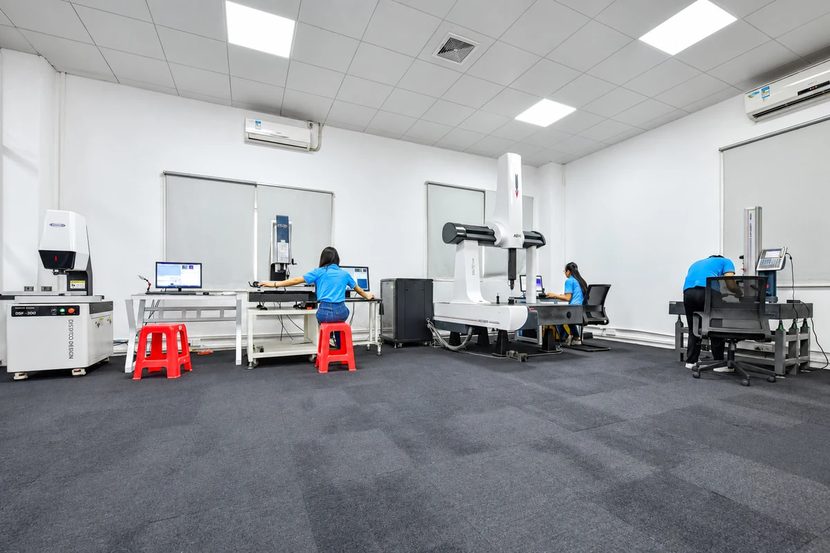
Clamping can temporarily distort thin or compliant parts. When the workpiece is released, residual stress and elastic recovery may change size or flatness. The manufacturing plan may require balanced stock removal, lower clamping force, additional supports, staged machining or measurement after release. Samshion’s quality assurance and inspection systems describe the broader controls used to verify manufactured parts.
Information to Include With a CNC Quote
- Native 3D CAD model and a controlled 2D drawing when tolerances or notes matter.
- Material grade, temper or condition.
- Quantity for the current order and expected repeat demand.
- Critical datums, fits, geometric tolerances and surface-finish requirements.
- Cosmetic zones and surfaces that must not carry clamp marks.
- Required finish, heat treatment, coating or outside processing.
- Inspection report, traceability and certification requirements.
- Mating-part or assembly information when it clarifies function.
- Target delivery date and whether design changes remain possible.
Request a Workholding and Setup Review
Send your CAD files, drawing, material, quantity and critical requirements. Samshion can review gripping surfaces, setup count, datum transfer, tool access, inspection needs and the likely balance between standard, modular and dedicated workholding. Upload your CAD files for a CNC quote.
Frequently Asked Questions
Why can one CNC prototype cost much more per part than a larger batch?
Programming, setup, workholding and first-off verification may be required before one acceptable part is produced. A larger batch can distribute reusable work across more accepted parts, although cycle time, material, finishing and inspection still apply to each unit.
Is a custom fixture always required for low-volume CNC machining?
No. Standard vises, chucks, collets and fixture plates are often sufficient. Soft jaws or a simple nest may provide the best balance for irregular geometry or a second operation. A dedicated fixture is justified when repeatability, access, quantity, cycle time or risk supports it.
Does five-axis machining eliminate setup cost?
No. It can reduce re-clamping and improve access, but programming, workholding, tool preparation, prove-out and inspection remain. The correct comparison is the complete manufacturing plan, not machine rate alone.
Can stronger clamping improve accuracy?
Only when the force safely seats a rigid part against appropriate locators. Excessive or poorly placed force can distort the part, damage a surface or move it away from its intended reference.
Are prototype fixtures disposable?
Not necessarily. Standard hardware, modular systems and some soft jaws can be retained for repeat orders. A fixture may become unsuitable if the design, datum scheme, material, machine or process changes, so identification and revision control are important.
What is the fastest way to reduce setup cost before ordering?
Provide complete files, functional datums, realistic tolerances, clear quantity and early DFM access. A stable revision and a practical gripping strategy often remove more uncertainty than simply requesting a lower price.