Electroless nickel plating adds a functional metal coating to a machined component. For a buyer ordering precision parts, the important questions are how that coating affects the finished dimensions, which surfaces must be plated, and what the drawing requires for acceptance. A coating decision made after machining can leave too little room for a bore, shaft or threaded connection to fit.
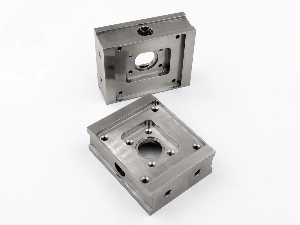
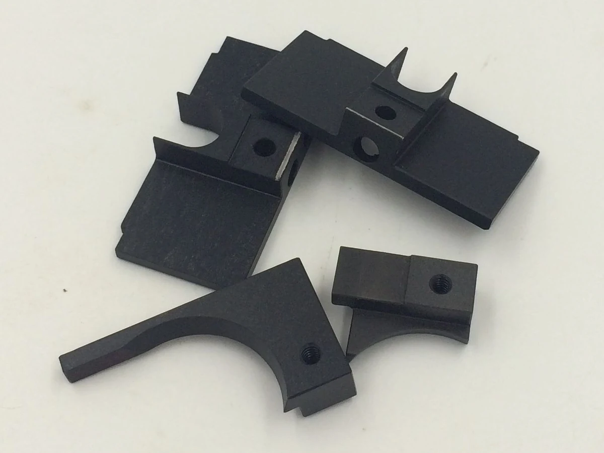
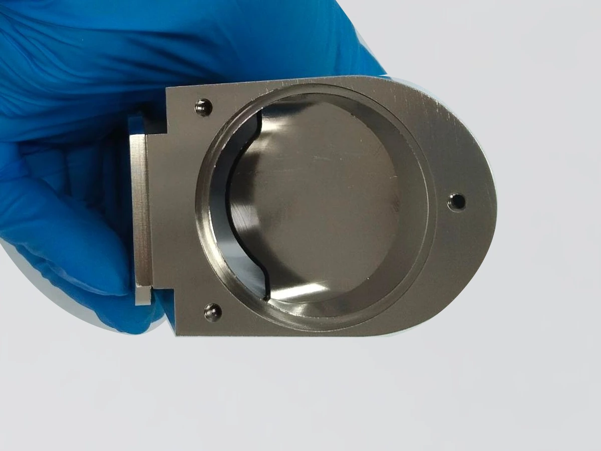
SAMSHION has supplied CNC machined parts with electroless nickel plating performed by an external finishing supplier. The photographs in this guide show our 6061 aluminum work. We manufacture and inspect to the customer drawing and coordinate the specified finish with the supplier. The discussion below explains what to define before production, especially when a component contains precision bores, threaded holes and mating surfaces.
What Electroless Nickel Plating Does
Electroless nickel plating, also called chemical nickel plating or autocatalytic nickel plating, deposits a nickel alloy through a chemical reaction without the external electrical current used in electroplating. Many functional applications use nickel-phosphorus deposits. The coating system, its composition and any subsequent treatment must match the specification for the part.
The process is valued for its ability to coat complex geometry with relatively even thickness. Aalberts surface technologies describes electroless nickel plating as a functional finishing process used on materials including aluminum and steel. Its coating properties are selected for the application, rather than determined by the silver appearance alone.
For a CNC component, this means the finish should be considered while defining the manufacturing route. A thin deposit can still consume a meaningful part of a tight dimensional tolerance. A visually similar component with a different coating specification may therefore require different machining allowances and inspection arrangements.
Electroless Nickel Versus Electrolytic Nickel Plating
Both processes can produce nickel-based finishes, but their deposition mechanisms affect the planning of a precision component. In electroplating, electrical current distribution influences coating thickness. Electroless deposition is less dependent on that geometry-related current distribution.
The comparison helps identify questions for the finishing supplier; it does not establish that one route suits every part. For broader process selection, see our CNC machining surface finish options.
Electroless Nickel Plating on 6061 Aluminum
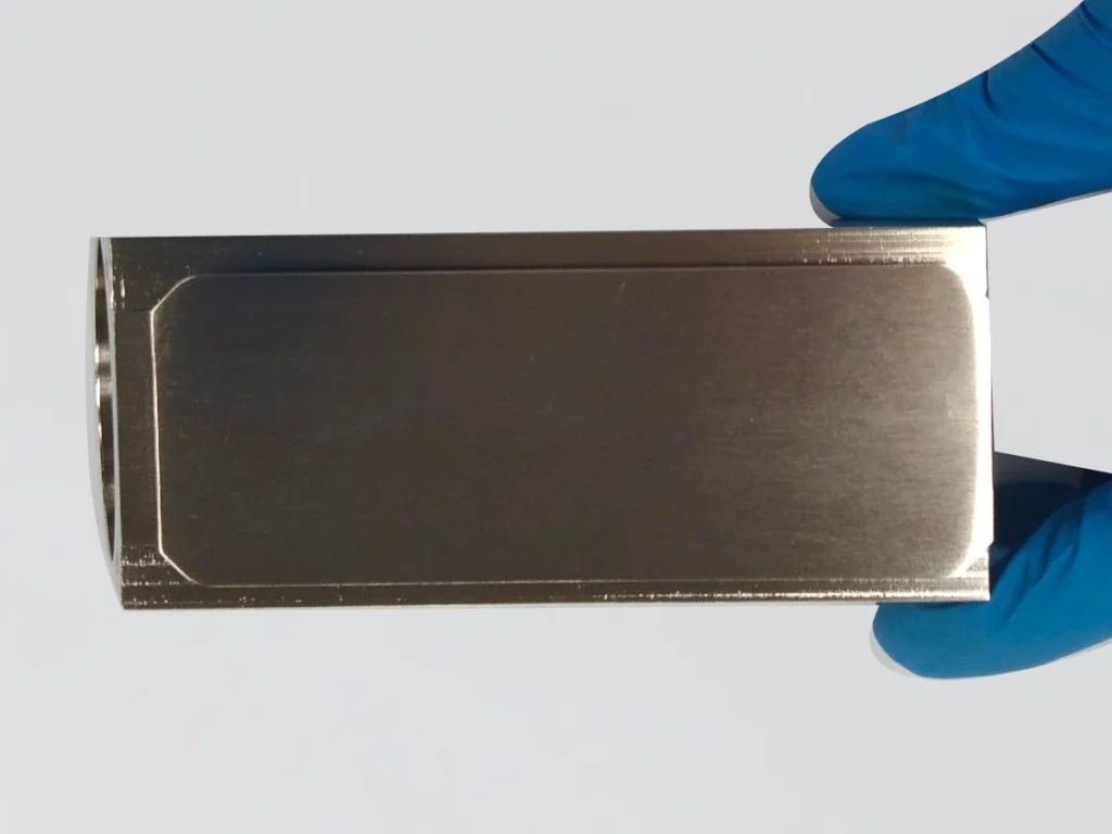
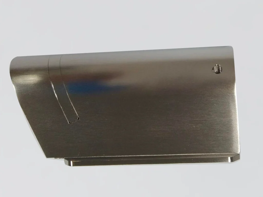
The illustrated 6061 components show the kind of geometry that needs coordinated machining and finishing requirements. Visible features include a large circular opening, smaller holes, a recessed side face and an exterior threaded hole. A purchaser should identify which of these features controls assembly and which surfaces have appearance requirements.
For a new 6061 aluminum order, the drawing should identify the material condition, coating specification, thickness and requirements for critical finished features. A photograph helps communicate shape and appearance; the drawing and order documents establish acceptance. Review those requirements together before selecting machining allowances.
Aluminum preparation also matters. Aluminum rapidly forms an oxide film, so the finishing supplier needs a preparation route suited to the alloy and coating system. Atotech explains zincate pretreatment for aluminum as one established approach before nickel deposition. The supplier selects the appropriate preparation steps for the specified substrate and finish.
For a new order, provide the complete material designation and any required condition or certification. Our 6061 aluminum CNC machining guide discusses the dimensional requirements that should be reviewed alongside the finish.
Specify Coating Thickness Before Setting Machining Allowances
Electroless nickel plating thickness should follow the required coating system and service conditions. There is no single thickness that should be applied automatically to all CNC machined parts. A purchase note that only says “nickel plate” leaves important decisions unresolved.
First establish whether the coating requirement is a minimum thickness, a nominal thickness with a permitted range, or another defined acceptance condition. Also identify the surfaces and locations where the requirement applies. A minimum value alone may be insufficient for a close fit if there is no agreed upper limit on buildup.
Phosphorus content is another specification variable for nickel-phosphorus coatings. Atotech lists low, medium and high phosphorus electroless nickel systems. These are coating choices with different intended properties. A machining supplier should obtain the required designation or arrange a review with the customer and finishing supplier, rather than select a class from appearance.
If a drawing invokes a standard, confirm its edition and the required classification. ASTM B733 addresses functional electroless nickel-phosphorus coatings and distinguishes composition, service condition and post-plating heat treatment. State the applicable ordering details so the customer, machining supplier and finishing supplier are working to the same requirement.
Any heat treatment must also be reviewed against the substrate and its material condition. A treatment selected for coating properties cannot be assumed compatible with every aluminum or steel component. Resolve the complete sequence before releasing the machining dimensions.
How Plating Changes Outside Diameters and Bores
Coating grows on the exposed surface. On a simple cylindrical outside diameter, buildup increases the diameter. On the inside wall of a bore, it reduces the available diameter. Micron’s coating thickness guidance discusses this dimensional effect and the need to account for it during machining.
For a preliminary geometric calculation, let t be the uniform coating thickness on each opposing surface. Using consistent units:
- Finished outside diameter is approximately the prepared outside diameter plus 2t.
- Finished bore diameter is approximately the prepared bore diameter minus 2t.
- A slot coated on both opposing walls becomes approximately 2t narrower.
Here “prepared” means the substrate immediately before deposition. Cleaning, etching and other preparation steps can also affect the surface, so the machining dimension cannot always be calculated by subtracting the nominal coating from the final drawing size alone.
As a hypothetical planning example, a uniform deposit of 0.010 mm on each wall reduces a bore by approximately 0.020 mm on diameter. This number illustrates the geometry only. It is neither the thickness of the photographed components nor a recommended value for a new order.
Include the Coating Range in the Tolerance Review
The permitted variation in coating thickness also affects the finished dimension. In the same simplified model, a bore with a prepared diameter between d_min and d_max and a coating range between t_min and t_max has an approximate finished range from d_min minus 2t_max to d_max minus 2t_min.
This is an engineering planning estimate, not a process capability guarantee. It makes a useful question visible: can the available final tolerance accommodate both the substrate variation and the agreed coating variation? If not, review the machining allowance, masking or an approved finishing sequence before manufacturing.
The same reasoning applies to a thickness measured across two plated outer faces. For a step length or a distance measured from a datum, identify the actual surfaces that define the dimension. If the datum surface is plated, its movement may matter as well. Avoid applying a blanket allowance to every dimension on the drawing.
Precision Bores and Recesses Need a Coverage Review
An external face is easier to see than the bottom of a blind bore or a narrow recess. Electroless deposition can reach complicated features, but coverage depends on the part and process arrangement. The public scope of ASTM B733 conditions uniform thickness on free circulation of the plating solution over the surfaces.
For electroless nickel plating of precision bores, tell the finishing supplier the bore diameter, depth, whether it is through or blind, and which internal surfaces require coating. Review intersecting holes, enclosed cavities and features where air or solution could be trapped. A coating requirement inside a hole also needs an appropriate way to verify it.
A reading on an accessible outer face does not automatically establish thickness at every recessed location. Where an internal feature is critical, agree on measurement access, sampling and any additional evidence before production. A witness sample can have a defined role in a test plan, but should not be assumed to represent every inaccessible detail of a complex part.
Threaded Holes Require Their Own Plating Allowance
Coating on thread flanks affects the fit of a threaded connection. The simple 2t rule for a smooth cylindrical diameter should not be transferred directly to thread pitch diameter. Thread geometry and the required final fit need a separate allowance review.
Specify the thread system, size, pitch, tolerance class and whether acceptance applies after plating. Then decide whether the threads will be coated, selectively masked, or processed through another approved sequence. A tap size or machining adjustment should follow that decision and the applicable thread requirements.
Thread gauges should be used for the specified acceptance condition. A thread that passed a gauge before plating has not thereby demonstrated acceptance after the coating has been added. Conversely, a gauge result addresses the thread features within its inspection scope, rather than coating adhesion or corrosion performance.
Chasing a plated thread with a tap can remove the deposit from functional surfaces. Do not treat this as an automatic correction for a tight thread. Review whether that operation is allowed and whether it would conflict with the specified coverage. Our CNC threaded hole guide covers the drawing information needed to define the thread before production.
Define Masking and Acceptable Contact Locations
Masking can protect a bore, thread, electrical contact or other surface that must remain unplated. It should be defined on the drawing or an agreed marked view. A clear boundary is easier to manufacture and inspect than a general instruction to “avoid plating the important areas.”
Review whether the boundary can be reached and controlled, and where a transition between plated and unplated surfaces is acceptable. Also identify surfaces where holding or support marks would interfere with a fit or an appearance requirement. The finishing supplier can then evaluate a suitable way to handle the part.
Masking adds preparation and handling work, so it can influence quotation and lead time. It is useful when required by the design, but should not replace a dimensional review. Some features can be machined with a suitable allowance and plated throughout; others need a different approved approach.
Surface Appearance Begins With the Machined Substrate
Electroless nickel should not be specified as a way to hide an undefined surface condition. Tool marks, scratches, edges and local geometry need an agreed acceptance requirement before finishing. If polishing or a particular texture is needed, include it in the manufacturing sequence and review its effect on dimensions.
For visible components, define which faces are cosmetic and whether an approved sample, surface roughness requirement or other reference controls appearance. Lighting and reflections can make the same plated surface look different in photographs. Color alone cannot establish the coating composition or thickness.
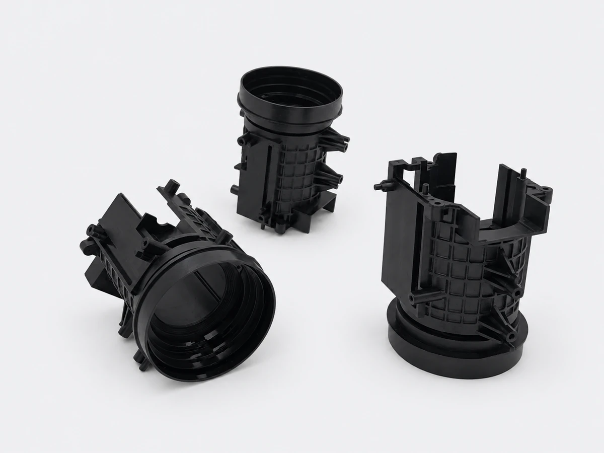
The photographs here illustrate actual component geometry and visible surface condition. They are not records of coating thickness, adhesion or corrosion testing. Keeping that distinction clear helps a buyer request the evidence the application actually needs.
Inspection of Electroless Nickel Plated CNC Parts
Start with the drawing and agreed inspection scope. For a precision component, the inspection plan should state which dimensions apply after the finish and which records are required from the finishing supplier. If a drawing is unclear about the measurement condition, clarify it before selecting machining allowances.
Dimensional inspection may include finished outside diameters, bores, step lengths, slot widths, threaded features and the relationship between mating surfaces. Choose instruments and methods according to the feature, tolerance and access. SAMSHION’s CNC machining inspection guide explains how drawing requirements guide that choice.
Coating thickness requires its own suitable measurement method and locations. X-ray fluorescence is one possible method when appropriate for the coating, substrate and geometry; other methods may be needed for different conditions. The ASTM B733 public abstract identifies several thickness assessment methods. Their suitability must be established for the actual job.
Adhesion, hardness and corrosion performance are separate requirements. Specify the test method, acceptance criteria, sampling and documentation when these are needed. They should not be added to a quotation as assumed routine tests, or inferred from a dimensional inspection report. Customer assembly or service testing should likewise have an agreed responsibility and scope.
If the supplier provides a coating certificate or test report, confirm that it identifies the relevant order or batch and the specified requirement. For repeat orders, keep the drawing revision and finish callout consistent with the approved manufacturing information.
Information to Include in an RFQ
A useful request for electroless nickel plated CNC parts includes the 3D model and a controlled drawing. The model communicates geometry; the drawing establishes dimensions, tolerances and finish acceptance. Include the following information where it applies:
- Complete base material designation, material condition and required certification.
- Coating specification, applicable edition and required coating designation.
- Thickness requirement, permitted range and locations where it applies.
- Dimensions and thread requirements that must be met after finishing.
- Plated areas, masked areas and acceptable transition or support locations.
- Cosmetic surfaces, roughness requirements and any approved appearance reference.
- Required coating tests, sampling, reports and responsibility for final application testing.
- Quantity, drawing revision and delivery requirements.
Cost depends on more than surface area. Selective masking, difficult access, close final tolerances, extra preparation and specified documentation can add work. Coordinating these requirements before machining gives the supplier a clearer basis for evaluating both price and delivery.
Frequently Asked Questions
Can 6061 Aluminum Be Electroless Nickel Plated
Yes. The 6061 components shown here are examples of SAMSHION machined work supplied with electroless nickel finishing through an external supplier. A new part still needs a coating and preparation route suited to its material, geometry and drawing requirements.
How Thick Should Electroless Nickel Plating Be
Use the thickness required by the applicable design and coating specification. Define the permitted range and where it applies. Choosing a number without the service conditions or final dimensional requirements can create a coating or assembly problem.
Will Electroless Nickel Change a Precision Fit
Yes. Buildup increases an outside diameter and reduces a coated bore or slot. Review the coating range together with the machining tolerance, and identify whether the drawing dimensions apply to the finished part.
Can Threaded Holes Be Plated Without Masking
They can be considered for plating when the process, allowance and final thread acceptance support it. Masking depends on the drawing and supplier review. Do not assume every threaded hole must be masked, or that a pre-plating gauge result proves the finished thread is acceptable.
Can a Photograph Prove Coating Quality
A photograph can show visible appearance and part geometry. It cannot establish film thickness, adhesion or corrosion performance. Request the specified inspection or test evidence when those properties control acceptance.
Discuss the Machined Part and Finish Together
SAMSHION machines components to customer drawings and coordinates electroless nickel plating with an external finishing supplier. For a new project, send the current drawing, material, quantity and finish requirements through our quotation page. Identify critical finished bores, outside diameters, threads and mating surfaces so the machining and plating requirements can be reviewed together.