CNC machining small features requires more than fitting a small cutter into the CAD model. The surrounding geometry must allow the tool to reach the full depth, remove chips and finish the required surfaces without damaging the material that remains. On a plate with a dense array of closely spaced pillars, a single bent feature or an incorrectly interpreted gap can affect an otherwise complete part.
The drawing should define feature width, height, spacing and the relationship to the mounting references. At SAMSHION, we prioritize controlling burr formation and removing burrs within the machining process where practical. If residual burrs cannot be removed that way, we use manual removal. The aim is to meet the drawing requirements while protecting the small features, rather than relying on hand finishing to correct their geometry afterward.
Review the small feature in its surrounding geometry
A short boss, a tall narrow rib and a deep slot may share one nominal width but require different manufacturing plans. For small feature CNC machining, the relevant geometry includes the unsupported height, depth of tool reach, neighboring features and available approach direction. The overall size of the component is often less informative than the space around its smallest details.
Dense arrays add repetition to the problem. The cutter must pass between successive features, and the process must preserve the relationship across the pattern. A change in tool condition or chip accumulation can affect later features even when the first few appear satisfactory. At quotation, review the array as a complete machining task rather than quoting one isolated pillar and multiplying its cutting time.
The term small feature does not establish a fixed tolerance or a particular machine category. Likewise, calling a component a micro-pillar plate does not mean it has micron-level tolerances. Feasibility depends on the drawing and inspection requirements of the actual part.
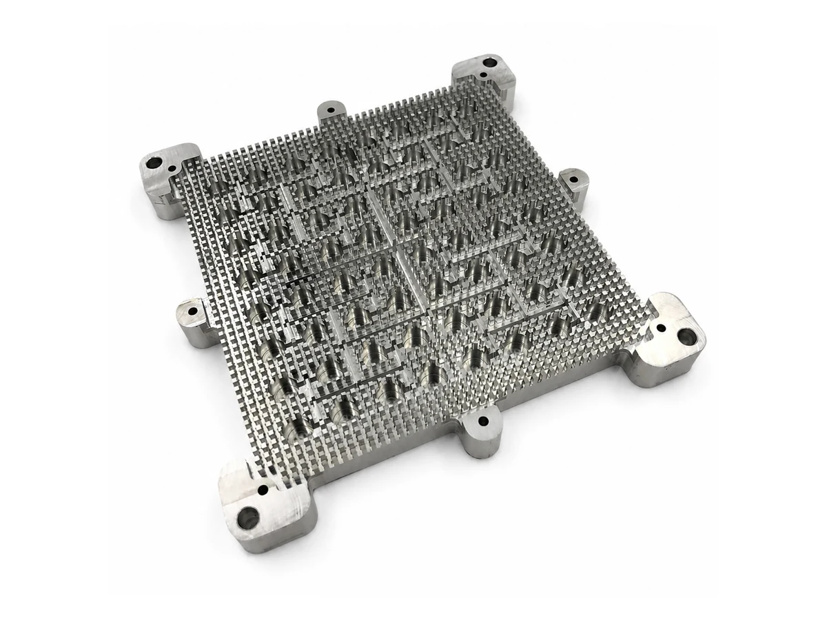
A machined aluminum pillar array example
Our CNC machining service page includes a research plate machined from 7075-T6 aluminum using 3-axis CNC milling. The approximately 150 × 150 × 15 mm component has repeated square pillars approximately 1 × 1 mm in section and 8 mm high, with approximately 1.2 mm clear gaps between adjacent pillars. It was supplied as an as-machined prototype.
The published project identifies narrow-channel access, small-tool stability, chip evacuation and protection of the pillars as machining considerations. It also describes a separate rear assembly face with drawing-defined parallelism and an approximate Ra 0.8 µm surface roughness target. Optical projection inspection was used for applicable small features, with visual inspection for remaining burrs and sharp edges.
These are project-specific dimensions and requirements. They are useful for discussing the geometry, but do not establish a universal minimum slot width, feature size or production tolerance.
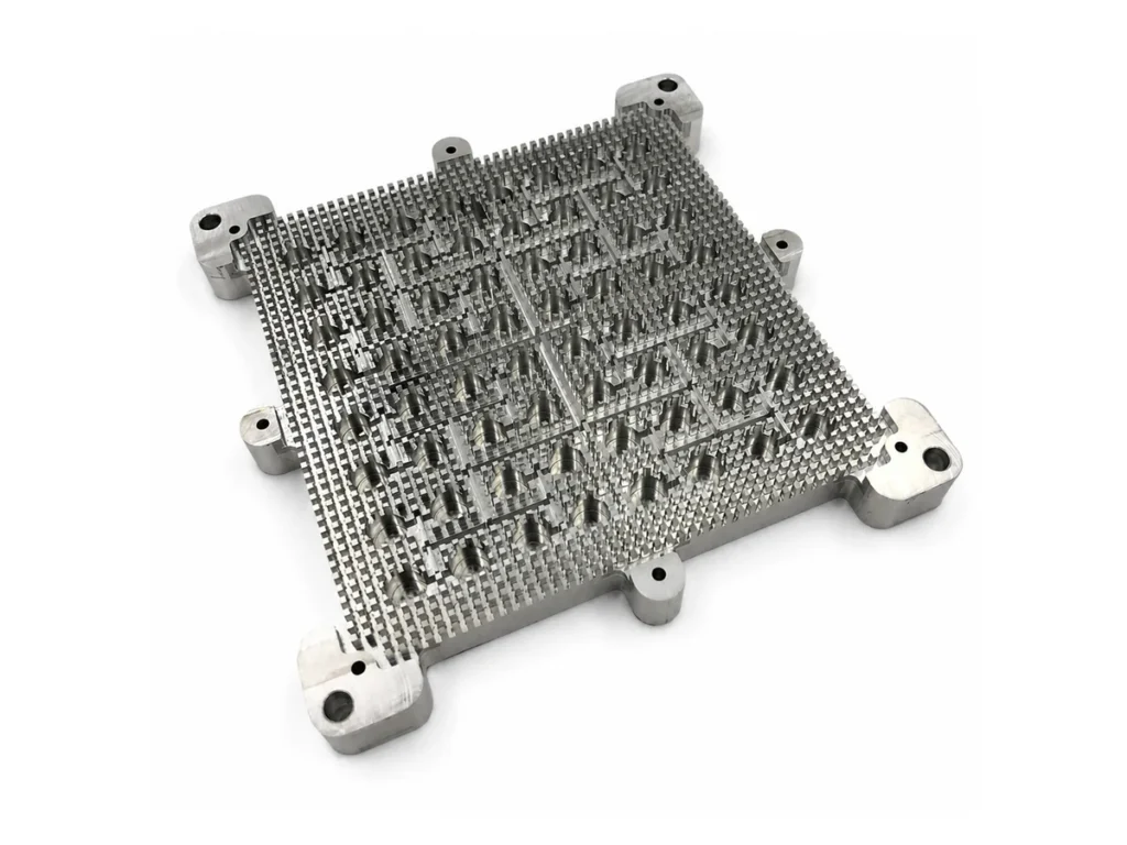
Distinguish pillar width clear gap and pattern pitch
A repeated feature drawing needs to identify what each spacing dimension measures. Pillar width is the material remaining across the feature. The clear gap is the open space between neighboring surfaces. Pitch is the distance between corresponding points, commonly the centers, of adjacent repeated features. Confusing the gap with the pitch changes the complete pattern.
For a simple regular row of equal square pillars, the nominal center-to-center pitch equals the pillar width plus the clear gap measured in that direction. A drawing should still specify which dimension controls acceptance. Applying independent tight tolerances to width, gap and pitch without checking their relationship can create conflicting requirements.
Also distinguish local spacing from the location of the complete array. Each neighboring pair can have an acceptable gap while the pattern is incorrectly located relative to a mounting hole or datum edge. Conversely, a correctly located array can contain an unacceptable local feature. The drawing should communicate both requirements when both matter.
If the feature has a taper, radius or other transition, define the section to which the size requirement applies. A single dimension at the top of a feature may not describe the required geometry farther down its sides.
Check tool access through the full slot depth
Narrow slot milling is constrained by the space available at every depth. A cutter may clear the slot entrance while its neck, shank or holder interferes with nearby material before the cutting edges reach the bottom. A manufacturability review needs the full 3D geometry, including bosses and mounting features outside the repeated pattern.
Tool diameter alone is therefore insufficient to judge access. Cutting length, relieved length, holder clearance and approach direction all need consideration. Long reach can also make the tool less stable. Sandvik Coromant guidance on milling vibration recommends keeping the tool assembly short and rigid and considering support from the workpiece and fixture. These are general principles, not a cutting-parameter specification for the research plate.
Closed slots and open-ended channels also differ. An open end may provide an approach route that a fully enclosed feature lacks. If a closed geometry makes access impractical, a different entry or an approved design adjustment may need discussion. Changes to the finished slot, pillar pattern or mounting interface require customer approval.
For a broader comparison of slot-making processes, see our CNC keyways and slots guide. The present article focuses on milling narrow spaces around delicate repeated features, rather than treating every keyway or slot as the same application.
Preserve support as the array takes shape
The workpiece changes as material is removed. Before the channels are cut, the stock around a future pillar can provide support. After neighboring material has been removed, that same region becomes an exposed slender feature. The sequence should account for this changing condition.
Roughing and finishing can serve different purposes. Roughing removes the bulk material while the remaining structure still provides support. Finishing establishes the required sides, heights and transitions with the remaining stiffness and tool access in mind. The suitable allowance and operation order depend on the geometry; there is no single sequence that fits every array.
The fixture also needs surfaces that can locate and support the part without loading fragile pillars. Where the design has a substantial base or suitable mounting features, those areas may provide useful support. A manufacturer should not assume that the small repeated features can act as clamping surfaces simply because they are available in the model.
This connects to thin wall CNC machining and distortion control, but the local problem is different. A broad thin wall and an individual narrow pillar respond to different support conditions. The useful review is feature-specific: what becomes unsupported, when that happens and which surfaces must remain accurate afterward.
Review cutter condition across the repeated pattern
A dense pattern can involve many repeated passes. The process review should consider whether tool condition, engagement or accumulated chips could produce different results in different areas. An acceptable first feature does not by itself establish the condition of the final row.
Harvey Performance guidance on miniature end mills explains why runout, tool extension and changing cutting loads become important as tool diameter decreases. It also describes how insufficient chip thickness can lead to ploughing rather than effective shearing. Simply reducing the feed as far as possible is therefore not a universal solution.
The practical response is to select the tool assembly and cutting conditions for the material, reach and required geometry, then review the results at appropriate stages. The customer’s inspection requirements should identify whether particular rows or regions need recorded checks. This does not imply a fixed tool-change interval or a full measurement of every feature on every order.
Keep the workpiece proportions separate from the tool proportions. Pillar height divided by pillar width describes the remaining feature. The cutter’s effective reach and diameter require their own review; they cannot be inferred from that ratio alone.
Control burrs during machining before using manual removal
Our first preference is to control burrs within the machining process where practical. Depending on the feature, the review may include tool condition, operation sequence, entry and exit conditions and access for a machining-based finishing pass. These are options to evaluate, rather than a promise that one method will eliminate every burr.
Where residual burrs cannot be removed in the machining process, we remove them manually. On a pillar array, this work needs to preserve the nearby sidewalls and top edges. An action that removes a burr but bends the pillar, rounds a controlled edge excessively or changes the slot width has not preserved the drawing geometry.
Small feature deburring therefore needs an acceptance requirement. Specify a permissible edge break or other edge condition when it matters. If an edge must remain sharp within a defined limit, say so. A general instruction to polish everything may conflict with the intended feature size or shape.
Our CNC deburring and edge inspection guide covers the wider subject. For dense features, add two practical questions: can the relevant edge be reached, and can it be checked without damaging the neighboring material? Visible-area inspection should not be described as verification of every concealed surface.
Inspect repeated features and mounting surfaces separately
An array can contain several inspection tasks. Pillar width, feature height, spacing and pattern location describe different characteristics. The base or rear mounting face may have its own flatness, parallelism or surface roughness requirements. One measurement should not be used as evidence for all of them.
For the published research plate, optical projection inspection was used to evaluate applicable small repeated features. That does not mean every surface at every depth is visible to the instrument, or that every future array will use the same measurement approach. Access, orientation, tolerance and the characteristic being measured determine the inspection plan.
In general, an optical outline can provide useful information about an accessible profile. It does not automatically establish the full geometry of an obstructed sidewall. Similarly, checking selected dimensions on a pattern does not amount to a documented full inspection of every pillar. If a report or coverage requirement is important, agree which characteristics and locations are included.
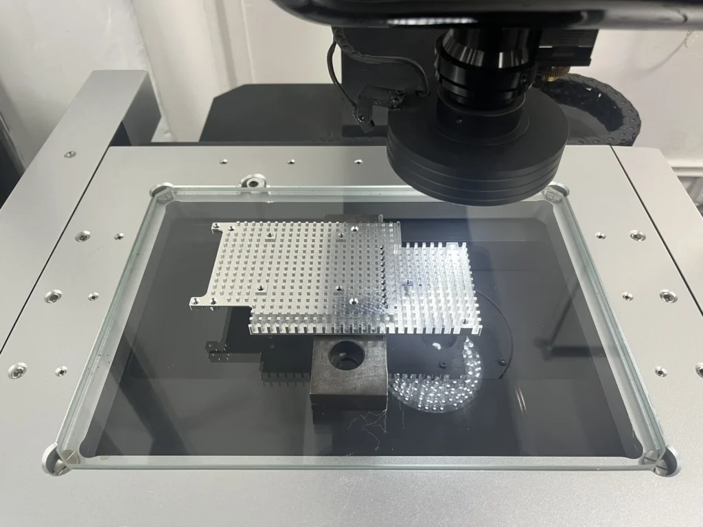
The mounting face should be treated as a separate functional surface. Flatness and parallelism answer different questions, while a roughness target describes surface texture rather than overall orientation. Keep the drawing reference, applicable face and required measurement evidence clear.
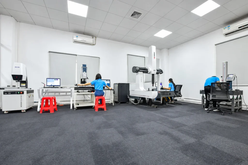
A photograph can illustrate a component or an inspection environment. It cannot supply measurement values, demonstrate full pattern coverage or establish compliance with a roughness requirement. When documentation is required, define the scope of the dimensional inspection report at quotation rather than relying on the appearance of a finished sample.
Avoid design changes that solve one issue by creating another
Increasing the clear gap can improve tool access, but it also changes the amount and arrangement of material remaining in the array. Reducing pillar height can improve support while changing the intended structure. Adding a larger root radius can make a transition more accessible while altering usable space near the base.
These can be reasonable design options when the customer approves them. They should not be made silently during programming. Identify the functional surfaces and dimensions first, then discuss which noncritical details can change. A useful DFM comment names the proposed change and the requirement it could affect.
Internal corners deserve particular attention. A rotating cutter leaves a radius in an accessible internal corner unless another approved method or geometry addresses it. Our internal corner radius guide explains the relationship among radius, tool access and cost. Do not request a sharp internal transition by appearance alone when the drawing needs to define its actual form.
Include the complete array in the quotation review
The price of a dense feature plate is not determined only by material weight. Repeated tool movements, restricted access, finishing, residual burr removal and the agreed inspection coverage can all affect the work. Two plates with similar overall dimensions may therefore require different quotations.
Provide the complete model rather than a cropped image of one feature. Include the number of repeated features, interrupted regions, mounting details and any areas where the pattern changes. A photograph is useful for discussion, but it does not establish hidden geometry, tolerances or the current design revision.
The RFQ should include:
- A current 3D model and a controlled 2D drawing with matching revisions.
- Material grade and condition, quantity and required final finish.
- Pillar or rib width, height and applicable size tolerances.
- Clear gaps, pattern pitch, array origin and the drawing-defined references.
- Slot depth, base transitions and any critical internal radii.
- Mounting features and requirements for the base or rear face.
- Required edge condition, appearance zones and acceptable burr limits.
- Inspection characteristics, requested report scope and delivery timing.
Where a requirement is still undecided, identify it before manufacturing release. For example, the customer may know the nominal pattern but still need to decide the tolerance on its position relative to a mounting interface. That missing relationship is more useful to resolve than adding a tight general tolerance to the entire drawing.
Send the files to SAMSHION for a machining review. We can assess the narrow spaces, repeated geometry and drawing requirements together, with any proposed design changes returned for approval.
Common questions about machining small features
Is there one minimum slot width for CNC milling
No single width applies to every component. Depth, tool access, material, surrounding geometry and the required tolerance all matter. A shallow accessible slot and a deep channel between tall pillars cannot be assessed from width alone.
Does a pillar array always require five axis machining
No. The published research plate was made using 3-axis milling. Other geometries may require different access or setups. Machine-axis count does not replace a review of the feature directions and holder clearance.
Are the clear gap and the pattern pitch the same dimension
No. The clear gap is the open space between neighboring surfaces. Pitch is the distance between corresponding points on repeated features. For equal square pillars in a regular row, pillar width plus clear gap gives the nominal pitch in that direction.
Are all burrs removed by hand
No. At SAMSHION, we first aim to control or remove burrs in the machining process where practical. Manual removal is used for residual burrs that cannot be removed that way, while protecting the required feature geometry.
Does optical projection inspection verify every feature in the array
Not automatically. The drawing characteristics, accessible profiles, inspection locations and report scope need to be defined. A statement that projection inspection was used is not evidence that every surface of every feature was measured.