Brass CNC machining is not just a question of whether a part can be cut quickly. For a component that must fit into an assembly, the important decisions include the specified brass grade, the machining sequence, the relationships between functional features, and how the finished surface will be protected and inspected.
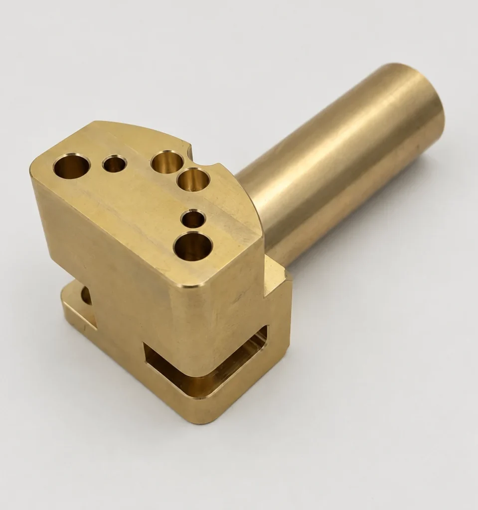
At SAMSHION, brass parts include H59 components made by turning followed by milling, as well as C360 components produced entirely by milling. These examples help explain a practical point: a round feature does not automatically make a part a turning job, and a material name alone does not define the manufacturing route.
This guide explains what to specify and review when ordering CNC machined brass parts. The photographs show our own as-machined components, without subsequent surface treatment. Background and exposure have been edited for presentation; the images illustrate product features, not measured tolerances or inspection results.
Start with the material grade on the drawing
For the components discussed here, the customer drawings specified H59 or C360. We followed those material requirements rather than selecting a different brass grade based only on appearance or perceived ease of machining.
H59 and C360 should not be treated as interchangeable labels. Before releasing a job, the purchasing specification, drawing and material identification should agree. If a material designation is unfamiliar or a proposed substitute is supplied under a different standard, clarify it with the customer before machining. A similar yellow color is not evidence of equivalent composition or performance.
In our experience with these particular parts, the practical machining differences between the two grades were not pronounced. That is a shop observation about these jobs, not a claim that every H59 and C360 stock condition behaves identically. Geometry, stock form, workholding and the required finish still affect process planning.
For buyers, the useful information is the complete material callout and any required documentation. State whether substitutions are prohibited or require approval, and identify material certification requirements at the quotation stage. Where an application has specific chemistry requirements, give the actual specification instead of assuming that a generic description such as “brass” is sufficient.
Choose turning and milling around the complete geometry
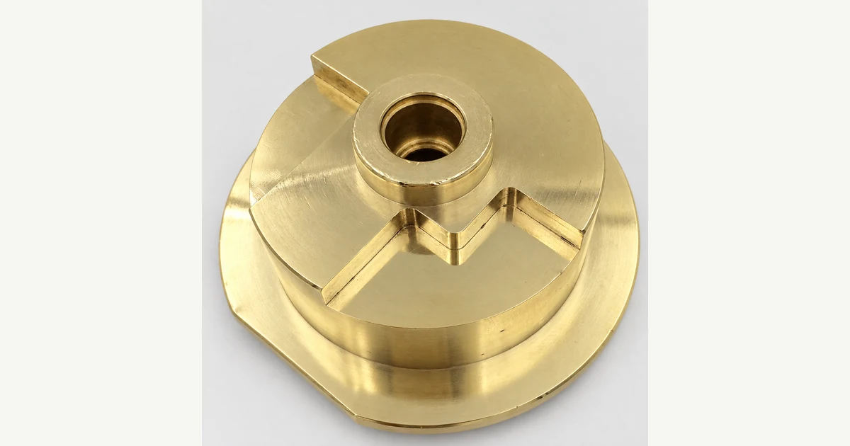
Turning followed by milling for the H59 component
The round H59 component shown below was turned first and then milled. Turning suits its rotational features; milling creates the features that are not rotationally symmetric. The important planning question is how the second operation locates the part relative to the features already machined.
For a part with a fitting diameter, a central bore and milled details, reviewing each dimension separately is not enough. If the drawing controls the relationship between those features, the locating method and inspection plan must preserve and verify that relationship across operations. The exact datum scheme depends on the drawing; the photograph alone cannot establish it.
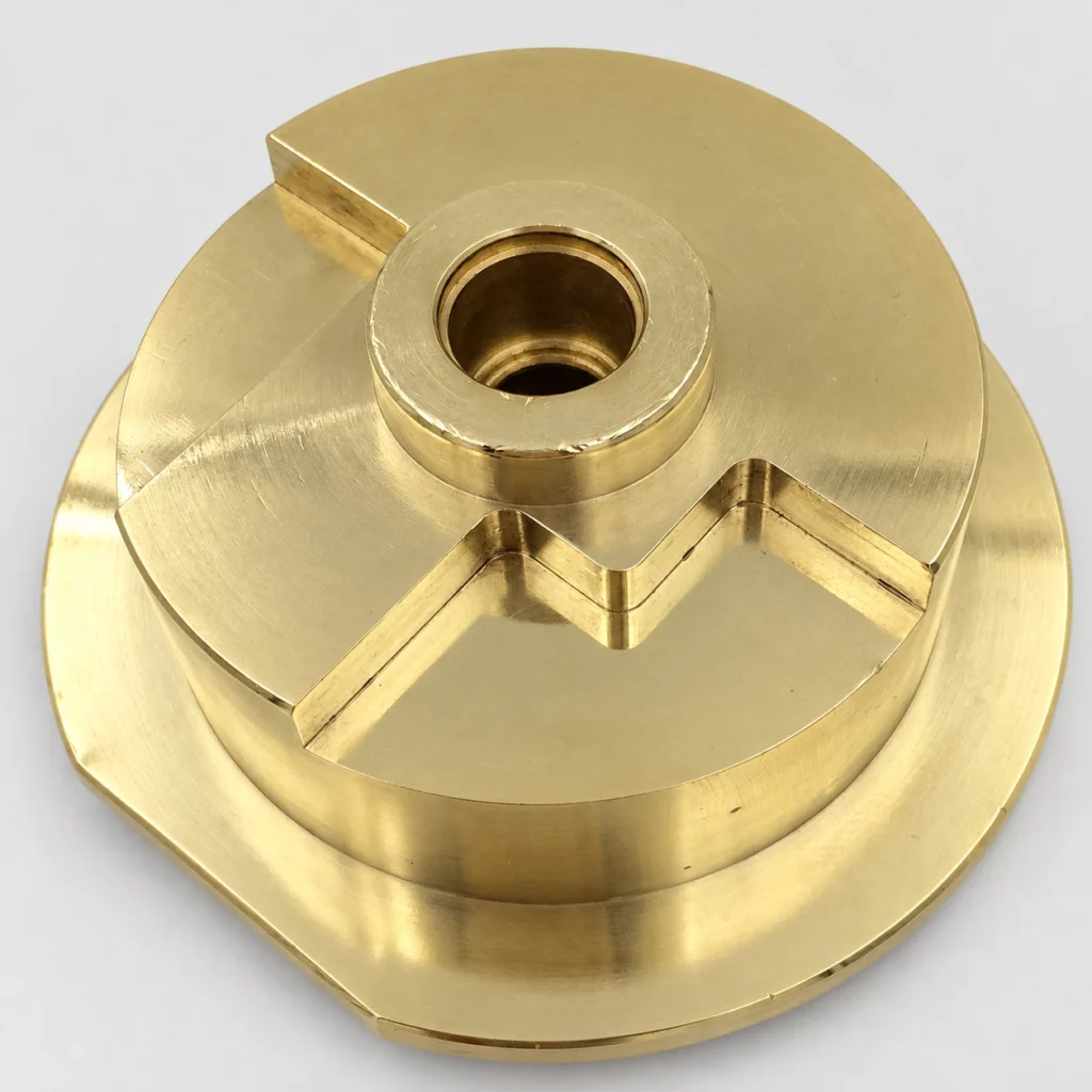
Our CNC turning services and CNC milling services can be combined where the geometry requires both processes. Combining processes does not imply that every part is made in one setup or on a turn-mill machine.
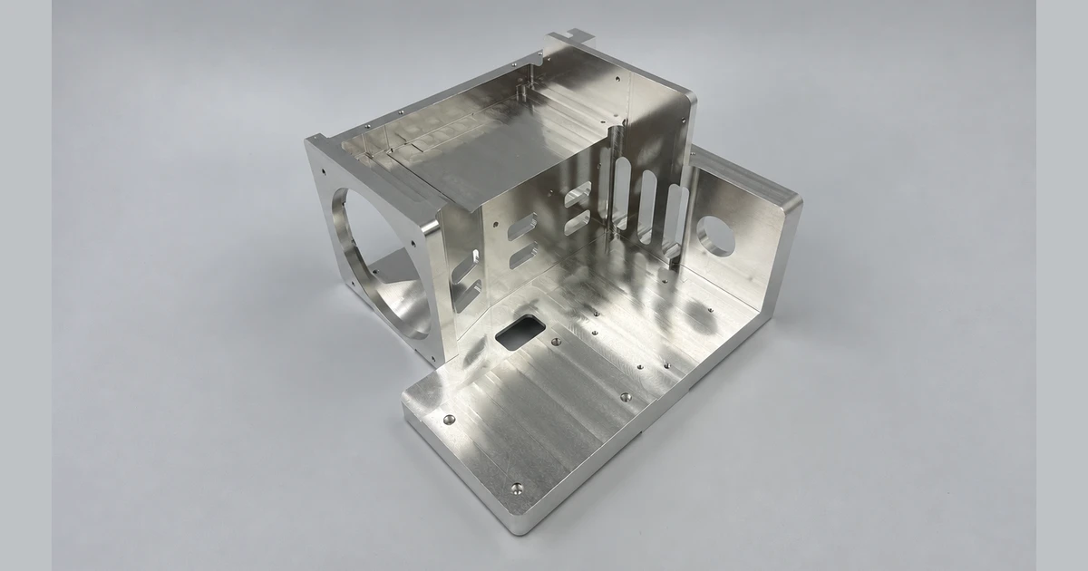
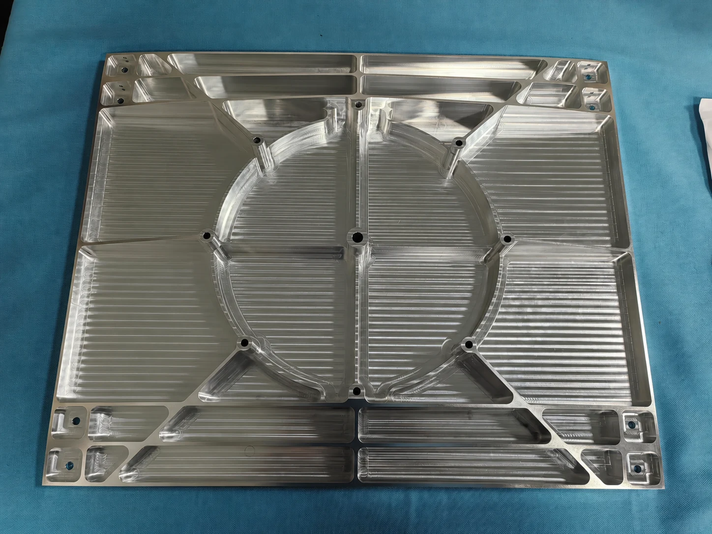
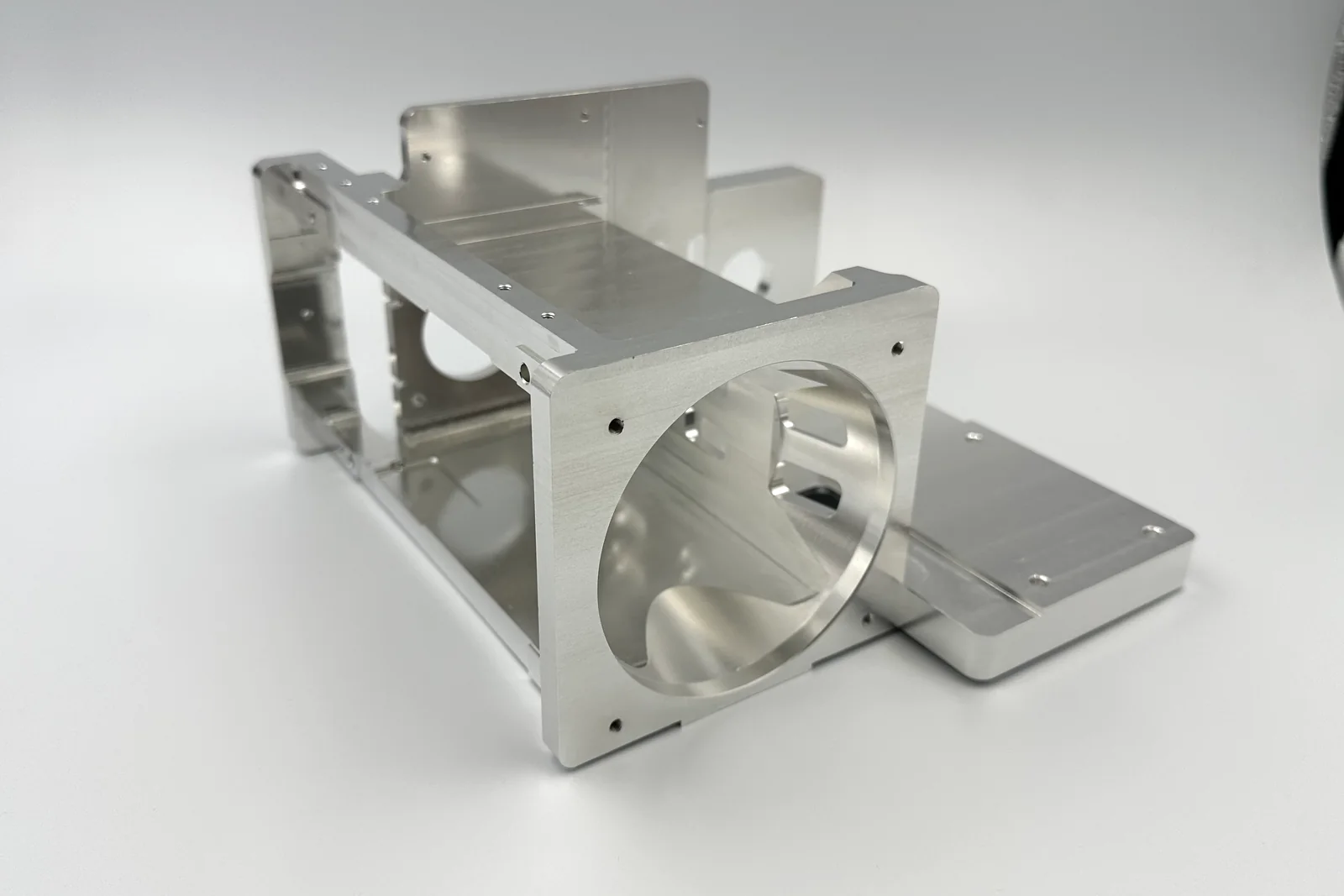
Entirely milled C360 components
The C360 components in this guide were made entirely by milling. One includes a cylindrical extension, but that feature was not turned. This distinction matters when evaluating a supplier’s proposed route: the full part geometry and available access matter more than the visual presence of a cylinder.
A useful process review considers which surfaces can locate the part, which faces must remain accessible, and whether reclamping could affect a critical relationship. There is no benefit in promising the fewest possible setups if that plan compromises support, access or repeatability.
Identify the features that control assembly
The brass jobs described here involved requirements such as internal diameters, fitting outside diameters, hole-to-hole relationships, slot widths and mounting faces. Not every visible feature has the same function or needs the same tolerance.
Bore and outside diameter requirements
A bore may guide, locate or receive another component. A fitting outside diameter may perform a different locating function. Specify the required size limits rather than relying on descriptions such as “tight fit.” If the relationship between a bore and an outside diameter matters, that relationship also needs an appropriate drawing requirement; acceptable individual diameters do not by themselves prove acceptable alignment.
For more detail on choosing the hole-making process, see our guide to CNC hole tolerances, drilling, reaming and boring. The brass material designation does not remove the need to consider access, depth and the specified hole requirement.
Hole relationships and mounting faces
An assembly can have correctly sized holes and still fail to fit if their locations are wrong. The drawing should make clear which references establish the hole locations and which mounting faces affect assembly alignment. Where a mounting face has a geometric tolerance, the inspection method must evaluate that particular requirement rather than only checking a few unrelated dimensions.
Slot width and usable geometry
For a slot that receives another component, review the width together with depth, internal corner geometry and access. A slot-width callout alone may not describe the entire fit. Any necessary corner relief, edge condition or clearance should be agreed before manufacture instead of being improvised during final assembly.
Protect brass surfaces during clamping and handling
Clamping impressions and surface scratches are practical issues we have encountered on brass components. They deserve attention during process planning, not only at the final visual check.
Our measures include using protective pads and controlling clamping pressure. The objective is to hold the component securely without leaving unacceptable contact marks. A pad is not automatically suitable for every setup: its thickness, support and possible movement need to be considered so that surface protection does not undermine positioning or rigidity.
The process plan should distinguish locating surfaces from clamping contact areas and identify any customer-designated appearance surfaces. Reducing pressure without checking stability is not a complete solution. Similarly, placing a protective layer on a critical locating surface can change how the part sits, so the setup must account for it.
Between operations and during storage, we separate components and use protective material to reduce part-to-part contact. Packing clean parts individually also helps prevent a finished face from rubbing against a neighboring edge. Handling protection matters even when no decorative finish is specified.
Define what an acceptable as-machined surface means
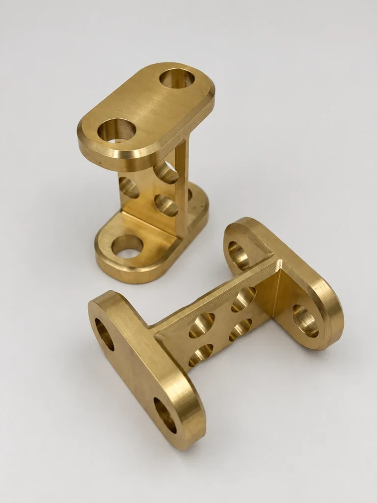
All the brass photographs in this article show parts after machining and before any subsequent surface treatment. The yellow color is the brass itself; it should not be described as a gold coating or evidence of polishing.
An as-machined surface can retain visible tool paths. Their presence alone does not establish whether a specified roughness or functional requirement has been met. Appearance, surface texture and dimensional acceptance should be considered separately, using the requirements on the drawing or an agreed inspection specification.
If some surfaces are cosmetic and others are functional, identify them. Explain whether handling marks are unacceptable on particular faces and whether an approved appearance sample is needed. This is more useful than a general instruction to supply a “perfect finish.”
If a later coating or other surface process is required, state it at quotation and define whether dimensional acceptance applies before or after that process. The examples here do not demonstrate a coated final condition, and no coating performance should be inferred from these photographs.
Match inspection methods to the specified feature
Inspection should follow the feature and its requirement rather than applying one instrument to everything. For our brass work, common methods include pin gauges or bore measuring tools for internal diameters, micrometers for outside diameters, CMM inspection for hole locations and mounting faces, and thread gauges for threads.
A pin-gauge check does not establish hole position. Slot inspection also needs a suitable method selected for its accessibility and drawing requirement. Agreeing the measurement approach before machining helps avoid disputes over what a reported result actually represents.
Where numerical results or a formal report are required, agree on the required features and reporting format before production. Our CNC machining inspection guide explains the broader role of inspection planning and dimensional records.
Information to include in a brass machining enquiry
A clear enquiry makes the quotation and manufacturing review more useful. Supply a 3D model where available, together with the controlled drawing and revision. Include the following information:
- The specified brass grade and any material documentation requirements.
- The quantity and expected delivery requirements.
- The functional dimensions, fits, datum references and geometric tolerances.
- Thread specifications, slot details and any features that are difficult to see in the model.
- The required surface condition, designated appearance faces and any later surface treatment.
- The inspection report requirements and whether acceptance is before or after subsequent processing.
- Handling or packaging requirements needed to protect exposed surfaces.
If a requirement is unclear, it is better to resolve it before machining than to rely on an assumption that becomes visible during assembly.
Frequently asked questions
Can a brass part combine turning and milling
Yes. The H59 component shown here was turned first and then milled. The process sequence should account for both the geometry and any required relationships between features produced in different operations.
Does a cylindrical feature mean the part must be turned
No. The C360 component with a cylindrical extension shown in this guide was made entirely by milling. The complete part geometry and manufacturing plan determine the route.
Can H59 be replaced with C360 without approval
Do not assume so. These are different material designations. For the examples here, the customer specified the grade, and any proposed substitution would need to be reviewed against the drawing and approved requirements.
Do these photographs show plated brass parts
No. They show as-machined brass components without subsequent surface treatment. They are product illustrations, not evidence of coating performance, surface roughness or measured tolerances.
Discuss the drawing before committing the process
Successful brass CNC machining connects the material requirement, process route, workholding, handling protection and inspection plan. Send SAMSHION your drawing, model, quantity and finish requirements to discuss a suitable CNC machining approach for your component.