Titanium CNC machining requires a process that controls tool wear before it becomes a dimensional or threading problem. A part may have acceptable external surfaces while a small blind thread remains the operation most likely to interrupt production. For engineers and buyers, the useful questions are which features drive that risk, how the machining plan addresses it, and what must be checked before acceptance.
At SAMSHION, our titanium machining experience includes TC4, Grade 5 and Grade 2. Two recurring challenges are rapid tool wear and broken threading tools in small holes and blind holes. We have experienced breakage with both taps and thread mills, with taps breaking more often in these jobs. Our responses include changing tools, adjusting spindle speed and feed, improving coolant delivery and chip evacuation, and considering thread milling where appropriate.
This guide explains those decisions and the drawing requirements that help a supplier plan titanium parts. It is intended for custom CNC components, rather than as a universal cutting-parameter recipe or a qualification guide for regulated end-use products.
Start with the specified titanium grade
The material name alone is not a complete purchasing specification. Confirm the grade, applicable material standard, supply condition and stock form against the drawing and material certificate. A familiar trade designation should not be treated as permission to substitute material supplied to another standard.
Grade 2 is commercially pure titanium. Grade 5 is the Ti-6Al-4V alloy. Their material properties differ, so a cutting process proven on one should not simply be copied to the other. TC4 is also among the designations we have machined; the actual purchase specification remains the controlling requirement for each order.
Material data should retain its grade and temperature context. For example, TIMET’s Ti-6Al-4V data sheet gives thermal conductivity of approximately 6.6 W/(m·K) at 20°C for the mill-annealed condition. TIMET’s Grade 2 data sheet identifies that material as commercially pure titanium. A single generic thermal-property value should not be applied to every titanium grade.
For a quotation, include any required material certification with the drawing. If the specified condition or stock size is unavailable, any proposed alternative needs engineering approval before procurement or machining.
Why tool life needs attention throughout machining
Heat concentrated near the cutting edge, adhesion and insufficient rigidity can make titanium machining unstable. The visible result may be worsening finish or burr formation before an obvious tool failure occurs. A worn or damaged edge can also change the cutting load and the size produced by an otherwise unchanged program.
Tool wear is only one possible explanation for a poor surface. Runout, excessive tool overhang, workpiece movement and chip recutting can produce similar symptoms. Replacing a cutter without checking these conditions may leave the underlying problem in place. Kyocera SGS’s titanium milling troubleshooting guidance discusses cutting conditions, rigidity and chip control as interacting factors.
How we decide when to change a tool
At SAMSHION, we combine observations during machining with replacement intervals based on machining time or part count. We watch for deterioration in the machined surface, dimensional deviation, increasing burrs and abnormal cutting sounds. These signs prompt a check rather than being treated as acceptable simply because a preset interval has not yet been reached.
The planned interval is specific to the job. Cutter size, feature depth and the amount of material removed can change how much work a tool performs on each part. A fixed number of parts is therefore not a transferable tool-life promise for all titanium orders.
For a buyer, this matters because dimensional control depends on more than the first acceptable part. A production plan should account for what happens as tools wear and after a replacement tool is introduced.
Match cutting conditions to the operation
An instruction to use low speed and high feed is too broad for a titanium component containing open faces, deep pockets and small holes. The same nominal feed can create different loads as the cutter engagement changes. Increasing feed without considering the tool and engagement can overload the edge; reducing it indiscriminately can create ineffective cutting.
Begin with the tool manufacturer’s recommendations for the actual material and operation. Then evaluate the complete setup, including tool diameter, cutting length, overhang, holder clearance and workpiece support. Where a low radial engagement strategy is suitable, its benefits depend on keeping the engagement controlled through corners and transitions, not merely selecting a high programmed feed.
Do not assign one finish requirement to every surface unless the function calls for it. Separating critical fits and datum faces from less demanding surfaces gives the supplier a clearer basis for selecting finishing operations and checking tool condition.
Cooling and chip evacuation
We use external coolant and internal coolant delivery, with high-pressure capability available. The delivery method is selected for the operation; the presence of a high-pressure system does not mean every cut uses the same pressure or arrangement.
The practical question is whether coolant reaches the cutting region and chips can leave it. An external nozzle that works on an open surface may be obstructed as a tool enters a pocket or hole. Internal delivery requires a compatible tool and coolant path. Pressure alone cannot compensate for a blocked passage, unsuitable tool geometry or inadequate space for chips.
When threading problems occur, our adjustments include coolant delivery and chip evacuation as well as the tool and cutting parameters. There is no single pressure, coolant concentration or cutting speed specified here: those settings must be matched to the equipment, fluid supplier’s instructions and tooling recommendations for the job.
Plan small holes and blind threads before machining
Small blind threads deserve attention during drawing review because the available tool section and chip space are limited. The drawing should distinguish the required full thread depth from the total drilled depth. A drill point, a tap’s lead and the space needed below the usable thread are different geometric requirements.
Before choosing a threading method, review the thread size, pitch and tolerance class, the prepared hole, full thread depth, bottom clearance and distance to surrounding walls. If a feature leaves insufficient room for the intended tool, the supplier should raise the conflict rather than silently changing the thread or drilling deeper.
Tapping and thread milling
Tapping can be suitable when the tap, prepared hole and chip-control strategy match the feature. Small taps have limited resistance to overload, and a blind hole restricts the route available for chips. Tool condition and the programmed approach to the hole bottom therefore matter alongside speed and feed.
Thread milling provides another way to produce the thread using a cutter smaller than the hole and an interpolated path. It can be useful when tap breakage risk is a concern, but it requires suitable tool clearance, reach and machine capability. Sandvik Coromant’s thread milling guidance discusses its use for difficult chip evacuation and features near the bottom of blind holes.
In our own work, both methods have produced broken tools, although taps have failed more often in the small and blind holes described above. We therefore treat a switch to thread milling as a process option to assess, not as a guarantee against breakage. A very small or long-reach thread mill still needs an appropriate load and a stable setup.
For broader drawing and method selection guidance, see our CNC threaded holes guide. On a titanium drawing, specify the functional thread requirement and let the process review establish a suitable method unless the manufacturing method itself is mandatory.
What happens after a tap breaks
When a tap breaks in these titanium holes, we use electrical discharge machining, or EDM, to remove it, then check the thread with a GO/NO-GO thread gauge. Removing the obstruction and accepting the thread are separate steps.
This recovery method should not be understood as a guarantee that every affected part can be retained. The remaining thread must still meet the drawing. Gauge acceptance also does not, by itself, establish every possible surface-integrity requirement. Where a customer restricts EDM or specifies additional acceptance checks, those conditions need to be addressed before recovery. No automatic repair or scrap decision is implied by the extraction step alone.
Check tool access and workholding alongside material removal
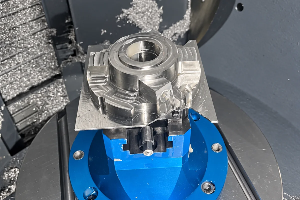
A pocket can be reachable by the cutting tip while the holder still conflicts with a wall. Extending the tool may create clearance but also reduce stiffness. Thin sections can move under cutting or clamping loads, so a process review needs to consider the support left around each feature as machining progresses.
These are reasons to discuss internal radii, pocket depth, narrow slots and access directions early. Where the design permits, a more accessible feature can allow a shorter or larger tool. Any change must retain the part’s functional requirements and receive the customer’s approval.
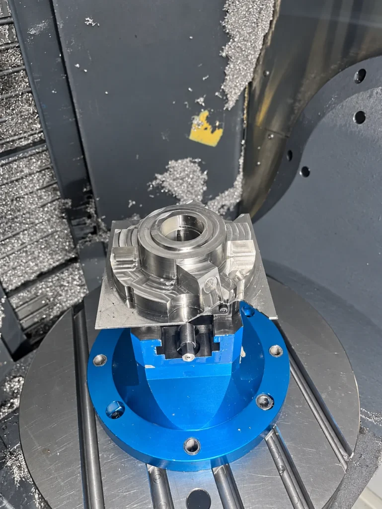
Five-axis machining can provide additional approach directions, but it does not remove holder interference or make a clamped face accessible. The machine’s rotary space and the fixture remain part of the access check. Our five-axis machining limitations guide explains these constraints in more detail.
For titanium, an access problem also affects the tool-life plan. A long-reach finishing tool working in a narrow area may need different cutting conditions and replacement expectations from a short tool machining an open face. Planning these operations separately makes the quotation and the process more realistic.
Define inspection and acceptance with the drawing
Identify the bores, fits, datum surfaces and positional relationships that control assembly. A dimension can be correct on its own while the relationship between two features is unsuitable for the mating components. The inspection method must match the characteristic being accepted.
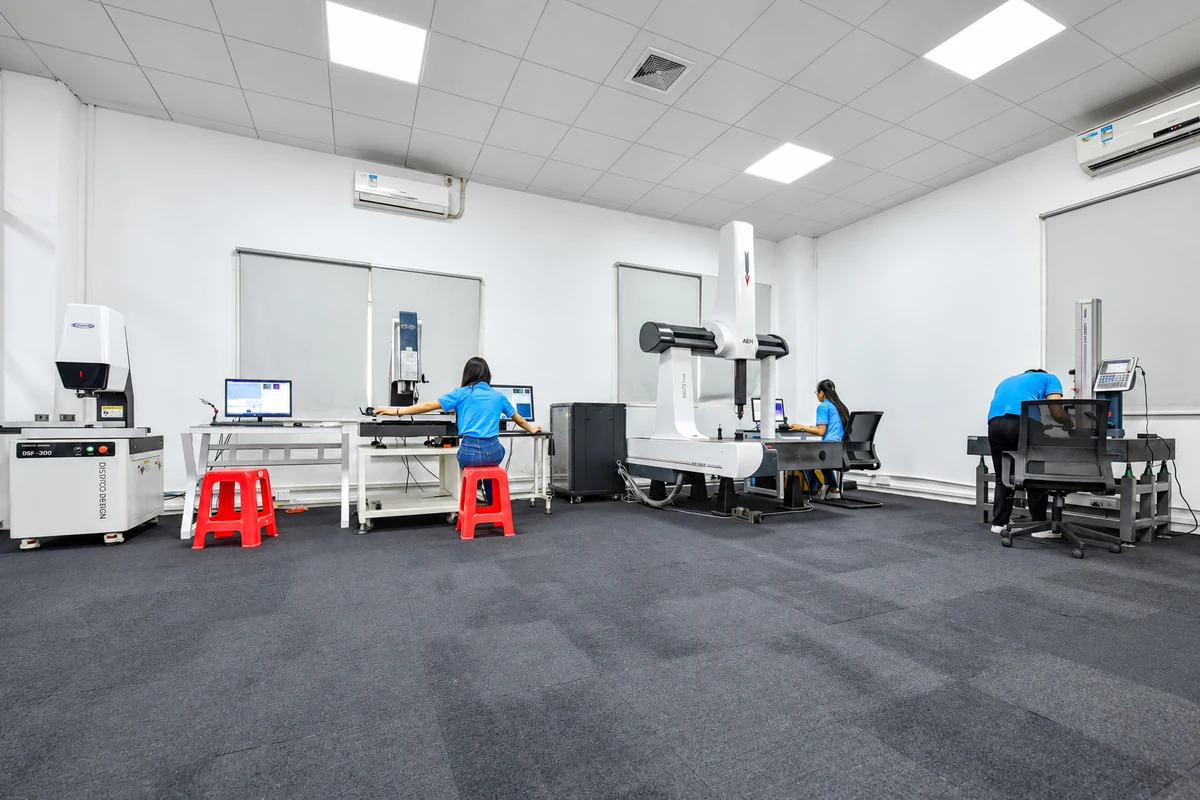
Thread gauging is the specific check confirmed in the tap-recovery procedure above. Other characteristics may require dimensional gauges, micrometers, CMM measurement or another suitable method according to their geometry and tolerance. The required method, report and sampling or full-inspection scope should be agreed for the order rather than assumed from a general equipment list.
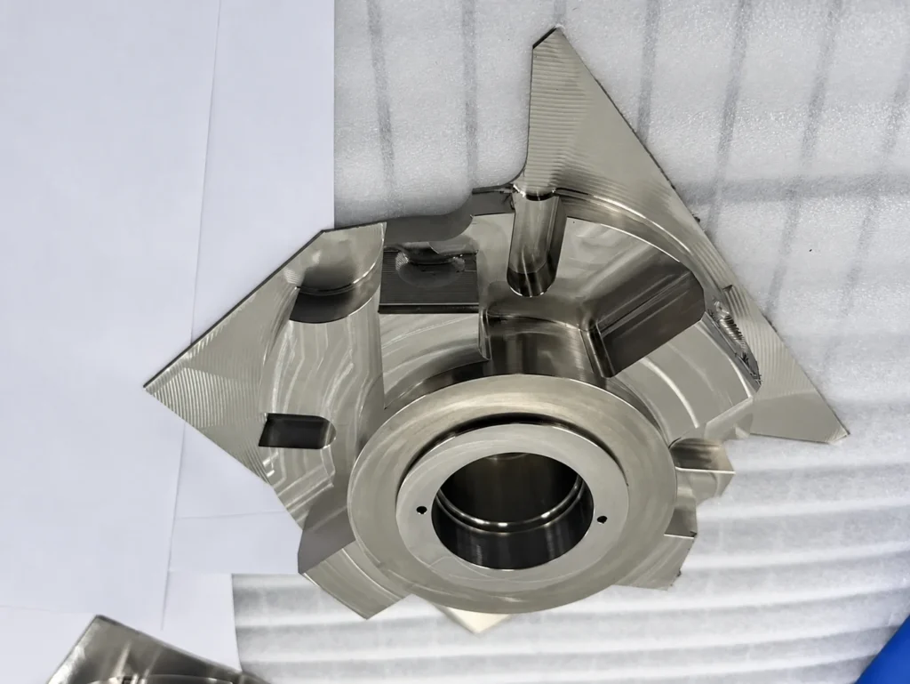
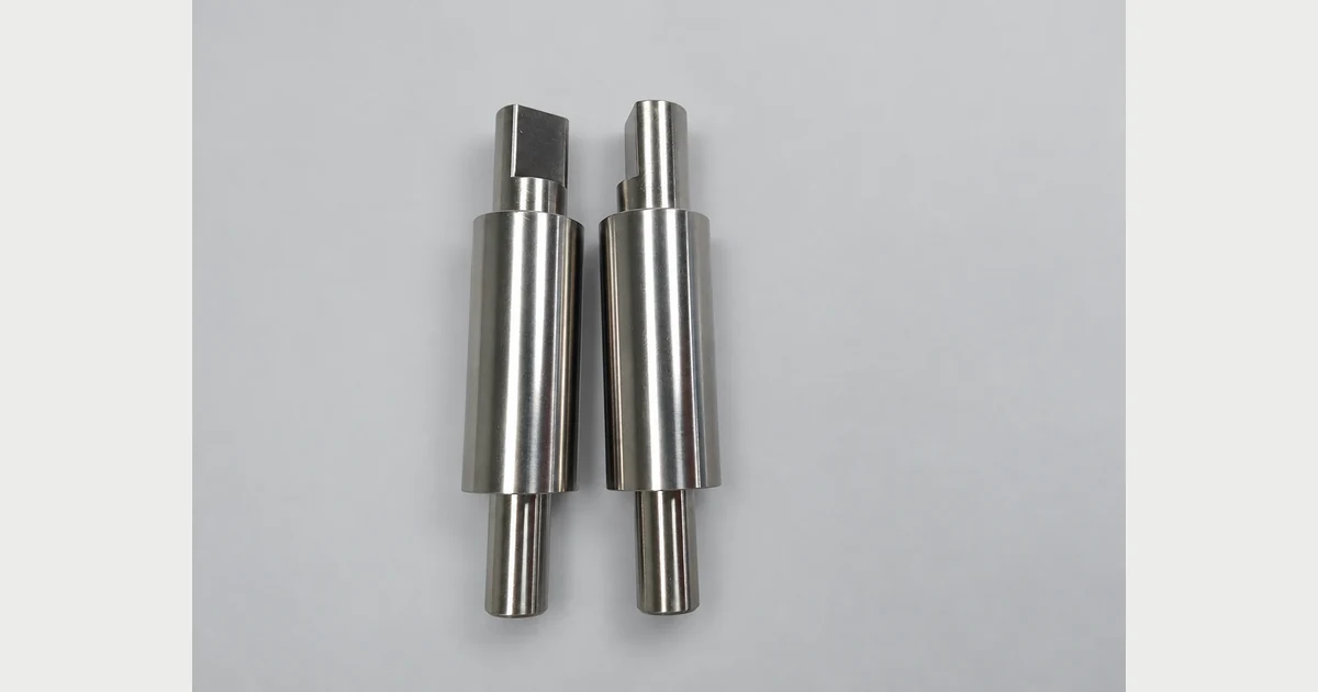
The photograph illustrates a titanium part we machined; it is not a measurement record. Surface appearance cannot establish the bore size, thread acceptance or positional accuracy. If documented results are needed, request them explicitly. Our guide to CNC inspection reports and material certificates explains how to distinguish dimensional results from other supplied documents.
What drives the cost of a titanium part
Material purchase cost is only part of the quotation. Small deep threads, long tool reach, repeated setups and extensive inspection can add work even when the finished component is compact. A thread failure late in the route can also put earlier machining time at risk.
Evaluate efficiency in terms of accepted parts and dependable delivery. A shorter cutting cycle is not necessarily a saving if it increases tool changes, recovery work or rejection. For comparison between suppliers, check whether they have quoted the same material condition, feature requirements and inspection scope.
Provide the following information with a titanium CNC machining enquiry:
- A 3D model and a revision-controlled drawing with dimensions that govern acceptance.
- The material designation, governing specification, supply condition and certification requirements.
- Thread size, pitch, tolerance class, full thread depth and relevant blind-hole geometry.
- Functional datums, critical fits and required surface finish or subsequent treatment.
- Quantity, delivery needs and the required inspection documents.
- Restrictions on process changes or repair methods, including EDM where applicable.
SAMSHION’s CNC machining services support review of the drawing and manufacturing requirements. Send the model and drawing together so tool access, threading risk and acceptance requirements can be considered before the process is agreed.
Common questions about titanium machining
Is Grade 2 processed with the same settings as Grade 5
Not automatically. Grade 2 is commercially pure titanium and Grade 5 is an alloy. Use the specified material and condition to select tooling recommendations, then assess the actual feature and setup. A familiar grade name does not replace a job-specific process check.
Does thread milling eliminate broken tools
No. We have experienced breakage with both taps and thread mills. Thread milling is an option when tapping presents difficulties, but tool size, reach, clearance and cutting conditions still need evaluation.
Can a broken tap be removed from titanium
Our approach is to use EDM for extraction and then check the thread with a GO/NO-GO gauge. Whether the component can be accepted depends on the remaining feature and all applicable drawing and customer requirements, not simply on successful extraction.
How often should titanium cutting tools be changed
There is no universal time or part count. We use planned replacement intervals together with observations of finish, dimensional deviation, burrs and cutting sound. The interval needs to reflect the work performed by that tool on that job.