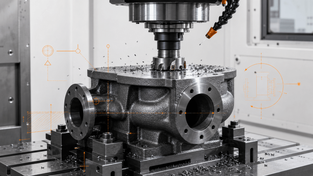
Cast iron is used for machine bases, pump bodies, valve housings, gearbox cases, engine components, tooling plates and other parts that benefit from stiffness, wear resistance, damping or economical near-net-shape production. Yet “cast iron” is not one machining material. Gray iron, ductile iron, compacted graphite iron, malleable iron and hard or alloyed irons can behave differently at the cutting edge.
The casting process adds another layer of variation. Surface scale, sand, chills, hard spots, porosity, inclusions, stock variation and residual stress may change from one region or heat to another. A program that works on a clean test coupon may not transfer directly to a large casting with interrupted surfaces and uneven stock.
Reliable cast iron CNC machining therefore begins with the material certificate and casting condition, not a universal speed, insert or coolant rule. It continues through datum planning, roughing, tool-life control, dust or fluid management, staged inspection and released-part verification. For the surrounding capabilities, visit Samshion’s CNC machining services.
What Makes Cast Iron Different From Steel?
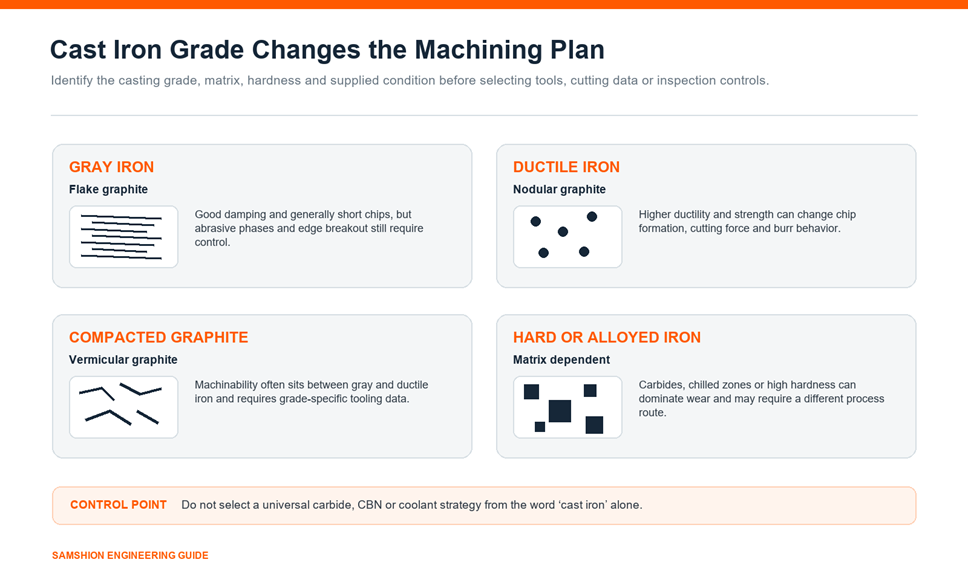
Cast irons are iron-carbon-silicon alloys in which carbon may appear as graphite, carbides or a combination depending on composition and processing. Graphite form and the surrounding metallic matrix strongly influence strength, damping, chip formation, edge breakout and tool wear.
Steel should not be used as the default mental model. Gray iron can form short, discontinuous chips because flake graphite interrupts the matrix. Ductile iron contains graphite nodules and usually combines greater strength and ductility with different chip and burr behavior. Compacted graphite iron has a vermicular graphite structure and often presents a different balance of cutting force, heat and tool life. Chilled or hard iron may contain carbides that make it much more abrasive and difficult to machine.
The Ductile Iron Society’s machinability research summary notes that machinability is affected by microstructure, graphite quality, pearlite content and casting hardness. This supports a practical rule: specify and verify the actual grade and supplied condition before selecting cutting data.
Identify the Cast Iron Grade Before Machining
Do not release a production process from a generic purchase description such as “cast iron.” Request the standard, grade, heat or lot identification, hardness range, heat treatment and relevant casting documentation. If material traceability is required, include it in the purchase order and inspection plan.
Gray Cast Iron
Gray iron contains flake graphite. It is widely used for structures that need vibration damping, dimensional stability and economical casting. Its chips are often short, but the graphite and matrix can be abrasive. The casting skin, sand contamination or locally hard areas may dominate insert wear during the first engagement.
Gray iron can also break away at unsupported edges. Feed direction, tool exit, remaining wall thickness and casting soundness should be reviewed when a machined face intersects a thin flange or bore.
Ductile Iron
Ductile iron contains spheroidal graphite nodules and generally provides greater ductility and strength than gray iron. Ferritic, pearlitic and mixed matrices have different hardness and machinability. Ductile iron may produce longer chips, higher cutting forces or more burr tendency than gray iron, depending on grade and condition.
A carbide grade and edge preparation intended for stable gray-iron roughing should not automatically be assumed optimal for a small ductile-iron finishing tool. Use tooling data that specifically covers the grade, operation and stability.
Compacted Graphite Iron
Compacted graphite iron, also called CGI, contains vermicular graphite. It is used in selected high-load cast components. Its machining behavior is not simply halfway between gray and ductile iron. Cutting data, insert grade, edge preparation and coolant policy should follow application-specific recommendations and shop validation.
Malleable, White and Alloyed Cast Irons
Malleable iron receives a heat treatment that changes its carbon structure. White iron and chilled regions contain hard carbides and can be extremely wear resistant. Alloying and heat treatment can further change hardness, strength and thermal behavior. These materials may require specialized carbide, ceramic, CBN, grinding or another route. Confirm capability before quoting them as ordinary cast iron.
Review the Casting Before CNC Setup
The machined part can only be as reliable as the casting and its process allowance. Inspect incoming castings before investing in expensive machining.
Confirm Stock and Datum Strategy
Compare the casting to the machining model or drawing. Check that each machined surface has enough stock while avoiding excessive, uneven material. Identify casting locators, parting lines, draft, core shift and the datums that will become the machining reference system.
Machining datums are not always the same as foundry-control datums. The Ductile Iron Society describes this distinction in a casting conversion case study, where casting and machining teams had to reconcile reference systems. Resolve that relationship before fixture design.
Look for Casting-Specific Risks
Potential risks include:
- Sand, scale or shot-blast residue on the surface
- Chilled or locally hard zones
- Porosity exposed by machining
- Inclusions or repaired areas
- Core shift that changes wall thickness
- Warpage or uneven stock
- Cracks, cold shuts or other unacceptable discontinuities
- Residual stress from solidification, heat treatment or straightening
Not every discontinuity is visible before cutting. Define who owns the response if machining exposes porosity or inclusions. The drawing, casting specification and commercial agreement should distinguish casting acceptance from machining workmanship.
Select Cast Iron Cutting Tools by Grade and Operation
Tool selection should account for the cast iron grade, matrix, hardness, casting skin, operation, engagement, machine stability and production quantity. No single material is best for every cut.
Coated Carbide
Coated carbide is a common starting point for milling, turning, boring and drilling cast iron. CVD-coated grades may provide wear resistance in stable roughing and medium operations. PVD-coated or tougher grades can support lighter cuts, smaller tools, less stable setups or selected ductile-iron applications. The exact choice belongs to the tool supplier’s application map.
Sandvik Coromant’s current milling-tool selection guide lists different grades for gray iron, nodular iron, stable or average conditions, roughing or finishing, and wet or dry machining. That range demonstrates why “use carbide for cast iron” is not a complete specification.
CBN and PCBN
CBN or PCBN can be appropriate for high-speed finishing, hard cast iron, continuous production or applications where wear consistency justifies the tool cost. It is not automatically required whenever a fine surface is specified. Interrupted cuts, unstable fixtures, heavy stock variation and unsuitable edge preparation can damage a brittle cutting edge.
Evaluate CBN from the actual grade, hardness, cut continuity, surface target, machine stability and economic tool life. Do not promise a particular roughness merely because a CBN insert is selected.
Ceramic Tools
Ceramic tools can support high cutting speeds in selected cast-iron turning or milling conditions. They require suitable machine power, rigidity, engagement and thermal control. Some ceramics are sensitive to impact or thermal shock. Use supplier-specific guidance and controlled trials rather than treating ceramics as a universal replacement for carbide.
Tool Geometry and Edge Preparation
Rake, clearance, edge hone, chamfer, insert shape and entering angle influence cutting force and edge strength. A heavily prepared edge may resist abrasion but increase force. A sharper positive geometry may reduce force on a thin or ductile feature but provide less edge security against casting skin or interruption.
The CNC cutting tool selection guide provides the broader relationship between workpiece material, tool material, coating, geometry and operating conditions.
Dry, Air-Assisted or Wet Machining?
Cast iron is frequently machined dry because graphite can provide some lubricity, short chips are often manageable and thermal cycling from intermittent coolant can damage certain hot inserts. However, “cast iron must always be machined dry” is also incorrect.
Coolant may be selected for holemaking, tapping, dimensional temperature control, chip evacuation, surface requirements or a tool grade designed for wet use. Some modern carbide grades are explicitly intended for either wet or dry cast-iron milling. The decision should consider the operation, tool supplier’s recommendation, machine enclosure, filtration, corrosion control and environmental exposure.
Avoid Intermittent Thermal Shock
If coolant is used, delivery should be stable and appropriate to the tool. A weak, intermittent stream onto a hot interrupted cutter can create thermal cycling. If dry or minimum-fluid cutting is used, provide effective chip and dust extraction rather than blowing contamination throughout the workshop.
Manage Metalworking Fluid Correctly
When fluid is used, maintain concentration, cleanliness, microbial control, filtration and mist extraction. OSHA’s metalworking-fluid best practices manual explains that fluids provide cooling, lubrication, corrosion protection and swarf removal, while poor fluid management can create health and process problems.
Control Cast Iron Dust and Chips
Dry cast-iron machining can create fine particulate mixed with chips. Graphitic dust can contaminate machine ways, tool interfaces, sensors, inspection surfaces and nearby work areas. Compressed air used without capture may simply redistribute the exposure.
Use suitable machine enclosure, local exhaust or extraction, chip collection and housekeeping. Protect measuring equipment and clean reference surfaces before inspection. Workers should follow the site’s risk assessment, safety data, applicable regulations and personal-protection requirements.
OSHA identifies inhalation and skin exposure risks associated with metalworking fluids and provides controls such as enclosures, optimized fluid delivery and local exhaust ventilation in its exposure-evaluation guidance. The specific controls for dry cast-iron dust should be selected by the employer’s qualified safety personnel.
Fixture and Datum Planning for Castings
Cast surfaces are not precision locating surfaces unless the fixture has been designed around their variation. Three-point support, adjustable locators, rest pads and controlled clamping may be needed to prevent rocking or distortion.
Establish Machined Datums Early
The first setup often creates a stable reference face, bore or pattern. Later setups should transfer from those machined datums where possible. Document which features locate, orient and support the part. Clean graphite and chips from every locator before loading the next casting.
Avoid Over-Clamping
A large housing can appear rigid but still distort when clamped across an uneven casting surface or thin wall. Measure critical features in the released condition unless the drawing specifies a restrained state. If a dimension changes after unclamping, investigate support, clamping, wall variation and residual stress.
The CNC fixturing and datum-transfer guide explains how locating, clamping and setup transfer affect repeatability.
Plan Roughing, Semi-Finishing and Finishing
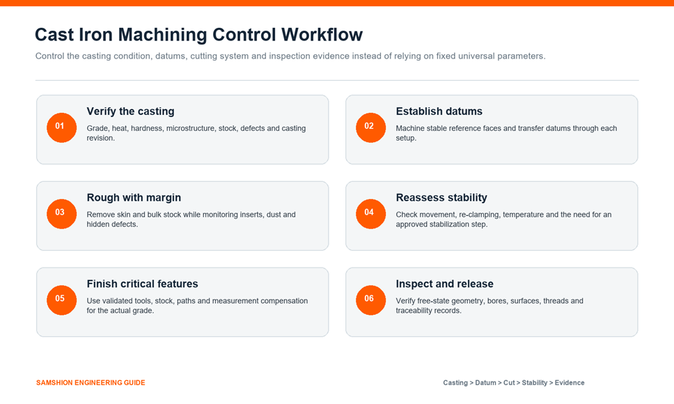
Separate stock removal from final dimensional control when part size, casting variation, stress or tolerance justify it. The correct number of stages and the stock between them depend on the casting and feature.
Roughing
Roughing removes casting skin and bulk stock, establishes access and reveals hidden defects. Tool wear may be highest when engaging abrasive skin, scale or sand. Leave enough controlled material for later correction, but do not apply one universal allowance to every casting size and grade.
Reassess After Major Stock Removal
Measure the part after roughing and release it from the fixture when the stability plan requires. If movement is significant, determine whether the route needs re-datum, a different support scheme, symmetric stock removal or a material-approved stabilization operation.
A fixed 24-to-48-hour wait is not a universal industry standard. Time alone does not guarantee stress relief. Thermal stress relief, natural aging, vibration treatment or simple re-clamping should be specified only when technically justified for the material, geometry and drawing.
Semi-Finishing and Finishing
Semi-finishing can restore uniform stock and prepare stable geometry. Finishing uses a controlled tool condition, engagement, temperature and inspection plan to establish critical dimensions and surfaces. Sister tools or tool-life limits can improve consistency in production, but the replacement point should come from wear data rather than a generic spindle-minute value.
Milling Cast Iron
Face milling is common for bases, covers and flanges. Cutter diameter, entering angle, pitch, insert geometry, engagement and machine power should suit the width and stability of the cut. Position the cutter and choose the path to avoid unnecessary repeated entry through casting skin or thin edges.
For pockets and contours, maintain controlled engagement and chip evacuation. A constant-engagement path can help with variable geometry, but it is not automatically required for every iron casting. Avoid recutting abrasive chips and clean the tool interface during insert changes.
At a fragile exit edge, reduce breakout risk through geometry, stock support, path direction, edge preparation or a sacrificial feature. Do not apply a fixed 50% feed reduction without validation. The required change depends on the tool, edge, wall and material.
Turning, Boring and Holemaking
Turning and boring operations must account for interrupted casting skin, bore distortion, tool overhang and insert wear. Critical bearing or sealing bores may require rough boring, released-state checking and a controlled finish pass.
Bores and Circular Features
Check cylindricity, roundness and taper rather than only diameter when function requires it. Thermal condition, clamping and tool deflection can cause a bore to measure differently after cooling or release. Use a stable boring system and a measurement method appropriate to depth and tolerance.
Drilling
Core shift and uneven stock can push a drill away from its intended path. Cast skin or voids may create interrupted engagement. Spotting, pilot strategy, drill geometry, coolant or air delivery and pecking should follow the tool system and actual depth. Verify position and true wall thickness when a drilled hole runs near a cored passage.
Threads
Thread quality depends on the cast iron grade, hole condition, engagement, tool form and lubrication strategy. Ductile iron can behave differently from gray iron. Thread milling may reduce risk for large or high-value parts because the tool does not become trapped like a tap, but tapping may remain efficient for stable production. Choose from the drawing, quantity, machine and recovery risk.
Control Tool Wear With Evidence
Cast iron can produce flank wear, abrasion, edge chipping, thermal cracking or notching depending on the material and cut. Inspect inserts at planned intervals and connect the wear pattern to dimensions and surface results.
Useful production records include:
- Tool and insert grade, geometry and lot
- Cutting time or number of components
- Machine, holder and cutter identification
- Casting heat or lot
- Wear images and replacement criterion
- Dimensional trend at critical features
- Surface result and any breakout or defect
- Coolant, air or extraction condition
Tool-life management can call a sister tool before failure, but it should not be described as measuring wear at the micron level unless the system actually measures wear. Many controls track time or usage and rely on validated replacement limits.
Surface Finish and Edge Integrity
Surface finish is influenced by tool geometry, insert runout, feed, speed, stability, wear, casting microstructure and exposed discontinuities. A polished-looking cut does not prove dimensional or material integrity.
Distinguish Machining Marks From Casting Defects
Regular feed marks may come from the cutting process. Random pits or open voids may be porosity. A torn edge can involve material breakout, insufficient support or tool condition. Record location and morphology before assigning responsibility.
Specify What Matters
State roughness parameters and cutoff conditions when function requires them. Also define flatness, sealing-band width, edge condition, porosity acceptance or visual requirements separately. The CNC machining surface-finish guide explains why roughness and post-machining finish should not be treated as the same requirement.
Inspection and Quality Control
Inspection should connect casting traceability, machining datums and functional features.
|
Requirement |
Suggested evidence |
Risk if omitted |
|
Material and casting identity |
Certificate, heat or lot, hardness where specified |
Wrong grade or uncontrolled lot variation |
|
Datum faces |
Flatness and datum relationship after release |
Downstream setup and assembly mismatch |
|
Critical bores |
Diameter plus roundness, cylindricity or position as required |
A bore can pass size but fail function |
|
Wall-sensitive features |
Position and wall-thickness verification |
Core shift or drill wander may remain hidden |
|
Sealing surfaces |
Flatness, roughness and documented visual condition |
Leakage despite acceptable average roughness |
|
Threads |
Gauge or functional inspection tied to specification |
Assembly failure or false acceptance |
|
Released-part stability |
Measurement in specified free or restrained state |
Clamping can mask distortion |
|
Production consistency |
First article and sampling or control plan |
Tool wear and casting variation go undetected |
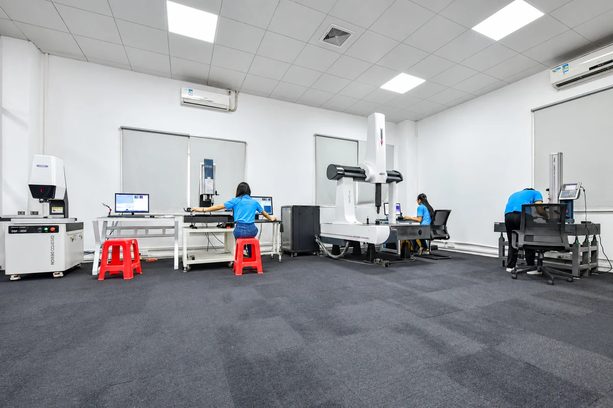
Clean graphite residue from datums and measuring contacts. Allow the part to reach the defined inspection temperature when tight dimensions justify it. The CNC machining inspection guide and Samshion’s quality assurance systems provide the wider planning and documentation framework.
Cast Iron Machining Troubleshooting Matrix
|
Symptom |
Contributors to investigate |
First controlled checks |
Verification |
|
Rapid flank wear |
Hard matrix, carbides, sand, casting skin, unsuitable grade or speed |
Confirm material and hardness; inspect skin and insert wear mode |
Tool-life trend by casting lot |
|
Insert chipping |
Interrupted cut, weak edge, runout, impact, unstable fixture |
Check cutter condition, engagement, clamping and edge preparation |
Wear image plus dimensional result |
|
Edge breakout |
Unsupported geometry, exit direction, defect, aggressive edge |
Review wall, path direction, tool condition and casting soundness |
Visual standard and edge dimensions |
|
Bore taper or out-of-round |
Tool deflection, clamping, temperature, wear, stress |
Measure in released condition and at several depths |
Bore geometry report |
|
Part moves after unclamping |
Uneven support, over-clamping, residual stress, stock imbalance |
Map support and measure before and after release |
Free-state inspection after revised route |
|
Random pits |
Porosity, inclusions, exposed casting defect |
Compare morphology and casting specification |
Documented disposition with foundry data |
|
Poor or inconsistent finish |
Insert runout, wear, vibration, material variation, recutting |
Inspect cutter, holder, wear and chip evacuation |
Roughness and visual record |
|
Dust contamination |
Weak extraction, compressed-air redistribution, housekeeping |
Review enclosure, capture and cleaning procedure |
Workplace and machine cleanliness record |
The matrix is a diagnostic starting point, not a substitute for the casting specification, tooling data or machine manual.
Information to Send for a Cast Iron Machining Quote
Provide:
- 3D CAD model and controlled 2D drawing
- Cast iron standard and exact grade
- Casting supplier, heat or lot requirements and material certificates
- Hardness or heat-treatment condition
- Raw casting model, drawing or inspection data where available
- Machining quantity and expected repeat schedule
- Critical datums, GD&T, bores, sealing faces and threads
- Surface roughness and porosity acceptance where relevant
- Casting stock and known core-shift or wall-thickness risks
- Coating, cleaning, pressure testing or assembly requirements
- First-article and production inspection documentation
Use the design for manufacturability guide to review geometry and tolerance risks, then upload your CAD files for an engineering review.
Frequently Asked Questions
Is gray cast iron easier to machine than ductile iron?
Often, but not always. Gray iron commonly forms short chips, while ductile iron may generate higher forces or longer chips. Matrix, hardness, graphite quality, casting skin and defects can outweigh the grade label. Use actual material data and tool-supplier guidance.
Should cast iron always be machined dry?
No. Dry machining is common, but wet machining may be appropriate for drilling, tapping, temperature control, chip evacuation or tools intended for coolant. Use stable delivery and suitable extraction or fluid management.
Is CBN required for a fine cast-iron finish?
No. CBN can be valuable in stable finishing or hard cast iron, but carbide, ceramic or another tool may meet the requirement depending on grade, continuity, quantity and economics. Surface finish must be verified, not inferred from tool material.
How much stock should remain after roughing?
There is no universal allowance. It depends on casting size, stock variation, stability, tool deflection, tolerance, feature and process route. Define it from the casting model, first-article evidence and finishing capability.
Does a cast-iron part need to rest for 24 to 48 hours after roughing?
Not as a universal rule. Time alone does not guarantee stress relief. Some parts benefit from released-state checking, re-datum or a specified stabilization process. The route should be justified by material, geometry and dimensional evidence.
How can porosity discovered after machining be prevented?
Machining cannot remove the root cause of casting porosity. Incoming controls, casting design, foundry process, radiography or other NDT where justified, and a clear acceptance standard reduce risk. Define disposition responsibility before production.
Conclusion
Accurate cast iron CNC machining comes from controlling the complete system: material grade, casting condition, stock, datums, tools, dust or fluid, staged machining and inspection. Replacing universal claims with grade-specific data and measured evidence improves tool life, dimensional stability and supplier communication.
For a technical review, upload your CAD model, drawing and casting information so the raw casting, machining route and inspection plan can be evaluated together.