Choosing between rapid tooling and production tooling is not simply a choice between a cheap mold and an expensive mold. The correct tool must match the design maturity, resin, part geometry, surface requirement, validation plan, expected production demand and acceptable business risk.
Rapid tooling can shorten the route to molded samples and low-volume production. Production tooling is engineered for repeatable manufacturing, maintenance and longer-term capacity. A bridge-tooling strategy can connect the two when demand is growing but the final production assumptions are not yet stable.
This guide explains how these tooling strategies differ, which cost and lead-time factors matter, how tool material affects performance and what information to provide when requesting custom injection molding services.
Key Takeaways
- Rapid tooling prioritizes speed, learning and lower initial commitment; production tooling prioritizes repeatability, throughput, maintenance and long-term manufacturing requirements.
- “Rapid” does not automatically mean aluminum, and “production” does not automatically mean fully hardened steel. Tool material is selected for the resin, geometry, finish, expected demand and maintenance plan.
- There is no universal quantity threshold, lead time, price ratio or guaranteed shot life that separates the two strategies.
- Cost should be compared as total cost per accepted part, including tooling, molding, validation, scrap, maintenance, modifications and schedule risk.
- Tight dimensions must be reviewed feature by feature. A production mold does not make every dimension controllable to +/-0.005 mm.
- The quotation should define tool ownership, storage, maintenance, expected use, approved resin, cavity count, sampling and transfer conditions.
What Is Rapid Tooling?
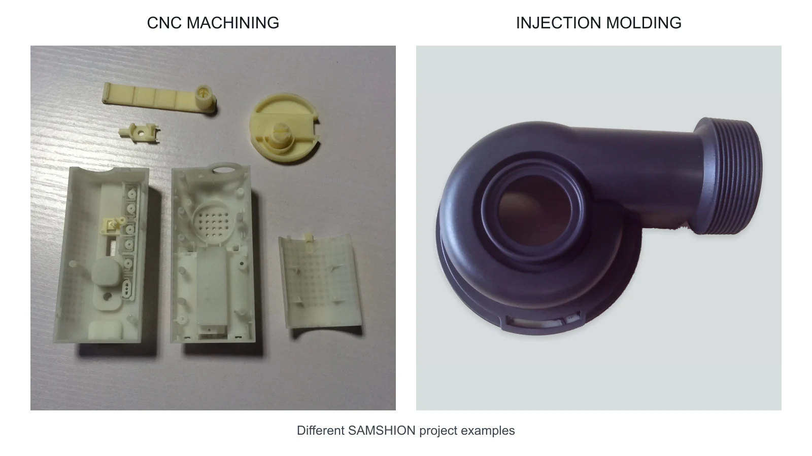
Rapid tooling is an injection-mold tooling strategy optimized to produce molded parts sooner and with less initial investment than a fully featured long-term production tool. It is commonly used for design validation, pilot builds, market testing, certification samples, low-volume orders and demand ramp-up.
The term describes the program objective, not one single construction method. A rapid tool may use:
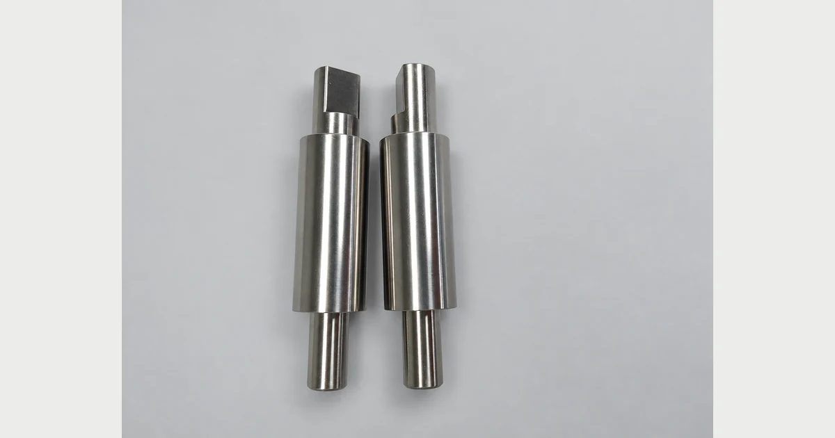
- Machined aluminum cavity and core inserts.
- Prehardened tool steel inserts in a standard mold base.
- Interchangeable inserts for several design variants.
- A single cavity where future production may use multiple cavities.
- Simplified automation, ejection or cooling where the intended run permits it.
- A mold architecture designed so selected inserts can be revised without remaking the entire tool.
A well-designed rapid tool should still produce representative parts in the intended production resin. It should control the functional dimensions, surface requirements and process conditions needed for the current validation stage.
Rapid tooling is not the same as vacuum casting, silicone molding or a 3D-printed visual prototype. Those processes may support product development, but they do not necessarily reproduce injection-molded material behavior, weld lines, gate effects, shrinkage, fiber orientation or ejection.
For programs that need molded parts before a final production tool is justified, review SAMSHION’s rapid tooling services.
What Is Production Tooling?
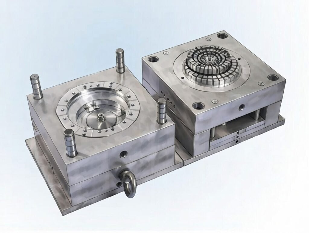
Production tooling is designed around a defined manufacturing plan. The mold must support the approved resin, output target, cycle-time objective, machine interface, quality plan, maintenance method and expected period of service.
Depending on the project, a production tool may include:
- Multiple cavities or a family-mold arrangement that has been technically justified.
- Hardened, prehardened or corrosion-resistant cavity and core materials.
- Replaceable wear inserts at gates, shut-offs, lifters and sliding interfaces.
- Hot-runner or cold-runner systems selected for material, waste and process stability.
- Balanced cooling circuits and temperature-control connections.
- Robust ejection, guided slides, lifters and interlocks.
- Sensors, robotic interfaces or automatic part handling.
- Spare components, maintenance instructions and defined tool-history records.
Production tooling should not be described only as a “hard mold.” A prehardened steel tool can be suitable for many production programs, while a hardened tool can still fail early if cooling, venting, steel support, processing or maintenance is poor.
SAMSHION’s production molding services combine tooling, process development, inspection and repeat-order manufacturing.
What Is Bridge Tooling?
Bridge tooling provides manufacturing capacity between early rapid tooling and the final long-term production system. It is useful when the design is largely stable and orders are increasing, but one or more production assumptions remain uncertain.
A bridge tool may:
- Supply launch quantities while a multi-cavity tool is being built.
- Use production-intent resin and geometry with a lower cavity count.
- Support regulatory or customer approval before final automation is released.
- Provide a backup source or spare capacity during ramp-up.
- Preserve insert geometry that can later be transferred or duplicated.
Bridge tooling should be planned deliberately. If it is treated only as a temporary purchase without documentation, it may create different gate locations, dimensions or cosmetic results from the final production tool. The transition plan should identify which characteristics must remain equivalent.
Rapid Tooling vs Production Tooling: The Core Differences
Program Objective
Rapid tooling is selected when learning speed, design flexibility and controlled initial commitment are the priorities. Production tooling is selected when the part and commercial plan are stable enough to optimize capacity, repeatability and lifecycle cost.
Design Maturity
A rapid tool can accommodate a higher probability of insert changes, gate revisions or local geometry correction. A production tool should be released only after the product definition, assembly interfaces and critical characteristics are sufficiently stable.
Tool steel can be modified, but changes become more expensive after heat treatment, polishing, texturing, hot-runner integration or multi-cavity matching. Freeze the correct requirements before investing in those steps.
Tool Material
Rapid tools frequently use aluminum or prehardened steel because these materials can reduce machining and heat-treatment steps. Production tools may use prehardened steel, through-hardened steel, corrosion-resistant steel or selected high-conductivity inserts.
Material choice depends on more than order quantity. Abrasive glass-filled resin, corrosive PVC, high-gloss optical surfaces and deep textured geometry can require different steel properties even at the same volume.
Cavity Count and Mold Architecture
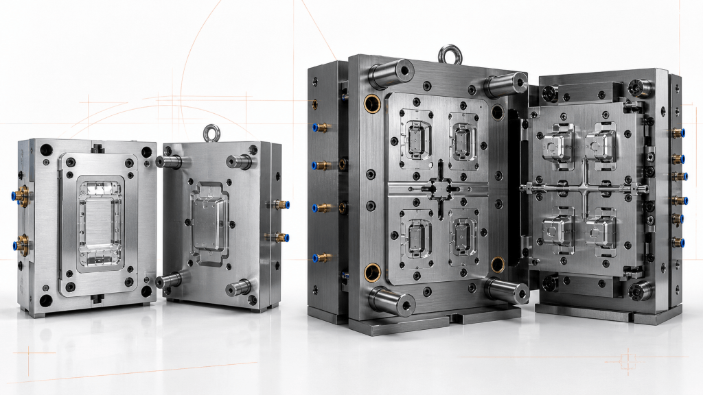
Rapid tools are often single-cavity or use a simple standard mold base. Production tools may use multiple cavities, hot runners, slides, lifters, unscrewing systems and automation. More cavities can increase output, but they also add balancing, cooling, validation and maintenance requirements.
Cooling and Cycle-Time Target
Rapid tooling may use a practical conventional cooling layout when the output requirement is moderate. Production tooling usually requires closer analysis of cooling balance, insert temperature, warpage and cycle time. A faster cycle is valuable only if quality and process stability remain acceptable.
Validation and Documentation
A rapid-tool program may focus on first-article dimensions, assembly and functional testing. A production-tool program can require a wider package: process-window development, cavity-to-cavity comparison, capability studies, material certification, control plan, gauge strategy, approved appearance samples and customer-specific documentation.
Maintenance and Spare Parts
Production tooling should identify wear components, lubrication points, cleaning intervals, storage protection and spare-part needs. The tool should be inspectable and repairable without losing cavity alignment or validated geometry.
Tool Ownership and Transfer
Tool ownership, storage location, permitted production site, maintenance responsibility and transfer conditions should be written into the quotation. If a tool may be moved later, confirm machine compatibility, locating ring, clamp method, water and electrical connections, hot-runner controller and documentation package before purchase.
How to Select Injection Mold Tool Material
Mold material must resist the actual failure mechanisms of the project. Relevant properties include hardness, toughness, wear resistance, corrosion resistance, polishability, machinability, thermal conductivity and dimensional stability during heat treatment.
The Uddeholm tool-steel guide for plastic molding explains that mold-material requirements depend on factors such as shot demand, plastic material, mold size and desired surface finish. This is why one generic “aluminum for rapid, H13 for production” rule is not technically sufficient.
Aluminum Tooling
Aluminum offers good machinability and high thermal conductivity. It can be effective for prototype, pilot and selected production applications, especially when geometry, resin and surface requirements are compatible.
Review aluminum tooling carefully when the resin is abrasive, the tool contains delicate shut-offs, the part requires deep texture or the program expects frequent maintenance. The mold-design engineer should select a tooling-grade aluminum and suitable mold-base support rather than assuming that every common plate alloy performs equally.
Prehardened Tool Steel
Prehardened mold steel can provide a useful balance of machinability, toughness, polishability and service performance without a separate final hardening operation. It is widely applicable to rapid, bridge and production tools. Local wear inserts can be hardened or replaced where the gate, slide or shut-off faces experience concentrated wear.
Through-Hardened and Corrosion-Resistant Steel
Through-hardened steels may be selected for high wear, demanding surfaces or long-term operation. Corrosion-resistant grades can be important for corrosive resins, humid operating conditions, cooling-system risk or medical and optical cleanliness requirements.
Heat treatment adds time and requires allowance for dimensional change and finishing. The benefit should be tied to a defined risk rather than specified automatically.
High-Conductivity Inserts and Local Solutions
Some molds use copper alloys or other high-conductivity inserts near hot spots. These materials can improve local heat transfer but may require support, coating, careful handling or planned replacement. Local solutions are often more efficient than assigning the most expensive steel to the entire mold.
Why Fixed Tool-Life Claims Are Misleading
Mold life is not determined by the base material alone. It is influenced by:
- Resin abrasiveness, glass or mineral reinforcement and additives.
- Melt temperature, injection pressure and gate velocity.
- Shut-off angle, slide travel and lubrication.
- Part geometry, texture depth and ejection load.
- Cooling-water quality and corrosion control.
- Cleaning method, preventive maintenance and storage.
- Unplanned crashes, insert loading errors and machine setup.
- Acceptance criteria for flash, texture and dimensional wear.
The Plastics Industry Association publishes an updated Customs and Practices of the Moldmaking Industry guide that includes mold classifications and approximate lifespans to reduce confusion during purchasing. A quotation should reference an agreed tool class or project-specific construction standard instead of presenting an unsupported guarantee such as “this mold always lasts five million shots.”
Expected life should be stated together with the approved resin, maintenance assumptions, tool construction and definition of end-of-life wear.
Tooling Cost: Compare Total Cost per Accepted Part
There is no dependable rule that rapid tooling always costs 30% to 60% of production tooling. Cost varies with tool size, cavities, actions, steel, hot runner, surface finish, tolerance, documentation and validation.
A useful commercial comparison includes:
Initial Tooling Cost
Include design, mold base, cavity and core machining, electrodes, heat treatment, surface treatment, hot runner, purchased components, assembly and sampling.
Part Conversion Cost
Include resin, machine time, labor, runner waste, automation, secondary operations, inspection and packaging. A less expensive single-cavity tool may have a higher unit cost than a multi-cavity production tool.
Validation Cost
Include dimensional reports, material certificates, capability studies, appearance approval, functional testing and customer-specific submissions. These activities may be larger cost drivers than the difference between two insert materials.
Modification and Learning Cost
Early changes are normal. Estimate the cost and schedule of inserts, welding, re-machining, texture repair and repeated sampling. A modular insert strategy can reduce risk when changes are expected.
Maintenance and Downtime Cost
Include planned cleaning, wear inserts, spare components, hot-runner service and lost production during repair. A tool that is inexpensive to purchase but difficult to maintain may increase lifecycle cost.
Schedule and Supply Risk
A delayed product launch, failed approval or missed repeat order can cost more than a tool-price difference. Bridge capacity, backup inserts and transparent tool documentation can have measurable commercial value.
Compare quotations using the same resin, cavity count, cycle target, quality plan, tool ownership and expected demand. Otherwise, the quoted prices do not represent equivalent solutions.
Lead Time: What Actually Controls the Schedule?
Tooling lead time begins after the design and commercial inputs are sufficiently complete. It is affected by:
- DFM closure and drawing approval.
- Tool size, cavities and mold-base availability.
- Slides, lifters, threads, collapsible cores and insert loading.
- Hot-runner procurement and electrical integration.
- Steel procurement, heat treatment, coating and polishing.
- Texture, engraving and cosmetic approval.
- Electrode quantity and EDM work.
- Cooling complexity and conformal-cooling inserts.
- Trial availability, resin availability and customer feedback.
- Dimensional correction and repeated sampling.
A simple tool may be completed quickly, while a small but highly complex tool can take longer than a larger conventional mold. Publish a project-specific schedule with review milestones instead of promising one fixed number of days for every rapid or production mold.
Tolerances and Surface Requirements
A production tool does not make every part dimension controllable to +/-0.005 mm. Plastic dimensions are affected by material shrinkage, moisture, fiber orientation, gate location, cavity pressure, cooling, part geometry and measurement conditioning.
ISO 20457 specifies possible manufacturing tolerances and acceptance conditions for plastic molded parts. It provides a formal reference, but the drawing still needs feature-specific tolerances and a functional datum system.
During DFM:
- Identify assembly, sealing and motion-critical dimensions.
- Apply geometric tolerances where they communicate function more clearly than blanket plus/minus limits.
- Separate molded dimensions from dimensions created by secondary machining.
- Define the measurement temperature, conditioning and fixture when soft or moisture-sensitive materials are involved.
- Evaluate dimensions across multiple cavities rather than reporting only one favored cavity.
Surface finish must also be specified. SPI polish level, VDI texture, Mold-Tech texture, gloss, grain direction and permissible witness lines require different steel and processing considerations. Review the injection mold surface-finish standards guide before approving the tool surface.
Tooling Selection Framework
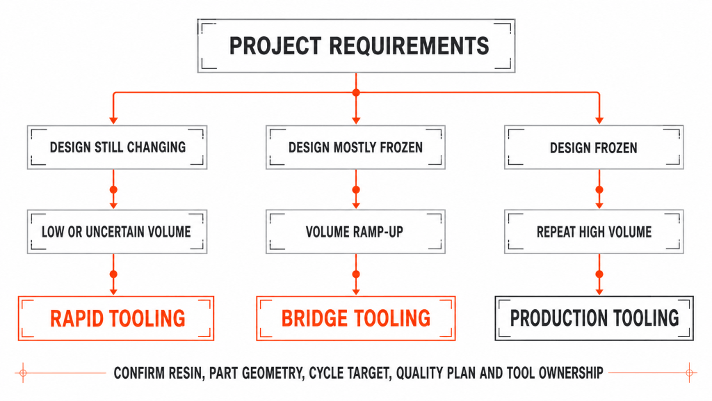
Use the following questions before choosing rapid, bridge or production tooling.
1. Is the Product Design Frozen?
If assembly interfaces, wall thickness, snap fits, sealing features or cosmetic surfaces are still changing, use a strategy that allows controlled insert revisions. A high-complexity multi-cavity tool is difficult to justify when the geometry is unstable.
2. How Certain Is the Demand Forecast?
Consider initial order, annual demand, peak monthly demand, product life and downside scenario. Avoid one universal quantity threshold. A large part with a long cycle may justify multiple cavities at a lower annual quantity than a small fast-cycling part.
3. What Resin Will Be Molded?
Confirm the exact commercial grade, filler, color system, recycled-content rule and regulatory requirements. Resin affects shrinkage, wear, corrosion, venting, gate design, temperature and surface quality. Review available injection molding materials before freezing the tool specification.
4. What Is the Part Complexity?
Slides, lifters, deep ribs, undercuts, threads, inserts, thin walls and large flat surfaces affect both tool construction and process risk. A complicated part may need production-grade local components even in a rapid tool.
5. What Quality Evidence Is Required?
Define first-article inspection, capability, cavity-to-cavity study, material traceability, cosmetic standards and functional testing. Medical, automotive and other controlled products may require a more rigorous validation path independent of order quantity.
6. What Cycle and Capacity Are Required?
Estimate machine size, cycle time, cavities, operating hours and expected yield. The tool must deliver accepted parts at the required rate, not merely demonstrate that one good sample can be molded.
7. Who Owns, Stores and Maintains the Tool?
Confirm ownership, permitted use, maintenance records, storage, insurance, expected service, modification approval and transfer conditions. These commercial details protect both parties when production continues for several years.
When to Choose Rapid Tooling
Rapid tooling is usually appropriate when:
- The design needs production-material validation.
- Demand is low, uncertain or still being tested.
- Samples are required for assembly, certification or customer approval.
- The program needs saleable pilot parts before final automation.
- Controlled revisions are more valuable than the lowest possible unit cost.
- A single cavity can meet the near-term schedule.
- The product may be replaced or revised before a long production run.
Do not choose rapid tooling only because its initial price is lower. Confirm that the tool can mold the required resin, produce the functional geometry and supply the forecast quantity with acceptable maintenance and yield.
When to Choose Bridge Tooling
Bridge tooling is appropriate when:
- The design is largely stable but final demand remains uncertain.
- Launch quantities are needed while the final production tool is under construction.
- The customer needs production-intent parts for approval and ramp-up.
- A backup or regional supply path is commercially valuable.
- A single-cavity or lower-cavity tool can temporarily support demand.
Define how the bridge tool differs from the final tool. Gate location, cooling, cavity count, resin, texture and processing can affect dimensions and appearance. Product approval should state whether data from the bridge tool transfers to the production tool.
When to Choose Production Tooling
Production tooling is appropriate when:
- The design and critical requirements are frozen.
- Demand is recurring and capacity can be calculated.
- Cavity count and cycle time materially influence unit economics.
- The product requires documented process control and repeatability.
- Resin wear, corrosion or surface requirements demand specific tool materials.
- Maintenance, spare parts, automation and long-term availability are required.
- The cost of downtime justifies robust construction and backup planning.
A production tool still needs sampling and correction. Higher initial investment does not eliminate the need for DFM, process development or maintenance.
How to Move from Rapid Tooling to Production Without Repeating Work
Use Production-Intent Resin Early
Material substitution can change shrinkage, warpage, weld lines, snap behavior, color and surface appearance. Use the intended commercial grade during relevant validation whenever possible.
Preserve Datums and Critical Features
Keep the same functional datum strategy, critical dimensions and inspection method across rapid and production tools. This makes data more comparable and reduces drawing interpretation changes.
Document the Proven Process
Record gate concept, venting observations, fill pattern, pressure response, cooling behavior, dimensional corrections and failure modes. The final tool does not have to copy every rapid-tool detail, but it should learn from the actual molded results.
Plan Replaceable Inserts
Where change risk is concentrated around clips, connectors, text, sealing features or cosmetic zones, use inserts that can be revised without replacing the full cavity block.
Define Transfer Validation
Do not assume that approval from a single-cavity rapid tool automatically approves a multi-cavity production tool. Plan first-article inspection, cavity comparison, appearance approval and functional testing for the final tool.
Retain a Backup Strategy
The rapid or bridge tool may remain useful for service parts, emergency orders, revisions or backup production. Document storage and maintenance instead of discarding it after launch.
Tool Sampling and Validation
DFM Approval
Close open questions about draft, wall thickness, ribs, bosses, undercuts, gates, vents, parting lines, ejectors, cooling, texture and inspection access before tool manufacture.
Initial Tool Trial
The first trial checks tool function, filling, ejection, cooling, flash, short shots and obvious dimensional issues. It is not automatically a validated production process.
Dimensional and Functional Review
Inspect critical dimensions using the approved drawing and datum system. Test assembly, sealing, loads and appearance. Review any correction against its effect on other features.
Process-Window Development
Establish a stable operating window for temperature, fill, pack, cooling and ejection. Avoid accepting a process that works only at one extreme setting.
Pilot Run
Run consecutive cycles long enough to expose thermal stabilization, insert-handling, cavity balance and quality drift. Measure yield and functional results, not only cycle time.
Production Release
Freeze the approved resin, master process, control plan, inspection method and maintenance requirements. Changes to tool, resin or process should follow an agreed review process.
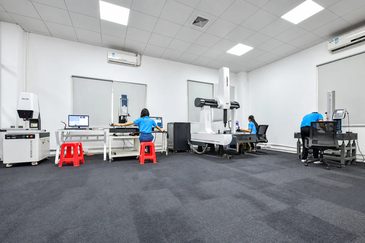
SAMSHION’s quality assurance system supports dimensional inspection, material verification and project-specific quality planning.
Information Required for an Accurate Tooling Quote
Provide:
- Native or STEP 3D CAD model.
- 2D drawing with datums, tolerances and critical characteristics.
- Exact resin grade, color and additive or filler requirements.
- Initial order, annual demand, peak demand and product-life estimate.
- Target tool location and injection-molding machine requirements if known.
- Surface finish, texture, gloss and cosmetic zones.
- Insert molding or overmolding requirements.
- Required documentation, inspection and capability studies.
- Packaging, assembly and secondary-operation requirements.
- Tool ownership, maintenance, storage and transfer expectations.
A quotation without these inputs may rely on assumptions that change the final cost and schedule.
Quote-to-Parts Process
1. Upload the Design Package
Send the 3D CAD model, 2D drawing, resin, quantity and application requirements.
2. Receive DFM and Tooling Recommendation
The engineering review identifies manufacturability risks and recommends rapid, bridge or production tooling with an appropriate cavity and material strategy.
3. Confirm Commercial and Ownership Terms
Approve the tool specification, schedule, sampling, inspection, maintenance, ownership and transfer conditions.
4. Manufacture and Sample the Tool
Review initial molded parts, dimensional results, appearance and functional performance. Correct the tool or process where required.
5. Validate and Release Production
Complete the agreed pilot run and quality records before repeat manufacturing.
Upload your CAD files to receive a tooling strategy and injection-molding quotation based on your actual geometry, resin, volume and validation requirements.
Frequently Asked Questions
Is Rapid Tooling Always Made from Aluminum?
No. Rapid tooling may use aluminum, prehardened steel or a combination of standard mold-base components and replaceable inserts. The choice depends on resin, geometry, finish, demand and risk.
Is Production Tooling Always Hardened Steel?
No. Some production programs are well served by prehardened steel, while others require through-hardened, corrosion-resistant or locally reinforced materials. Tool construction should match the failure risks and manufacturing plan.
How Many Parts Can a Rapid Tool Produce?
There is no reliable universal number. Tool performance depends on resin, filler, gate design, shut-offs, ejection, process conditions, maintenance and acceptance criteria. Request an expected-use statement tied to these assumptions.
When Should We Move to Production Tooling?
Move when the design is stable, repeat demand is credible and production capacity, unit economics, validation or maintenance requirements justify the investment. A bridge tool can support the transition when demand is rising but final assumptions remain uncertain.
Is Rapid Tooling Suitable for Saleable Parts?
Yes, if the tool, resin, inspection and regulatory plan are appropriate. “Rapid” describes the tooling strategy, not a lower quality requirement. Product acceptance must still be defined.
Can a Rapid Tool Be Upgraded into a Production Tool?
Sometimes. Replaceable inserts, standard mold bases and documented interfaces can support upgrades, but a simple single-cavity tool may not economically accept the cooling, hot runner, cavity count or automation required for production. Plan upgradeability during DFM.
Which Tool Has the Lowest Cost?
Rapid tooling normally reduces initial commitment, but production tooling can reduce unit cost and downtime at scale. Compare total cost per accepted part over realistic demand scenarios.
What Causes Tooling Quotes to Differ So Much?
Quotes may assume different steel, cavity count, mold base, hot runner, cooling, actions, texture, validation, expected use, maintenance, ownership and sampling. Compare the written specifications, not only the final price.
Request a Tooling Strategy Review
The best tooling decision balances speed, learning, production economics and risk. Send SAMSHION your CAD model, drawing, resin, expected quantity, surface requirement and quality plan. Our engineering team can recommend a rapid, bridge or production tooling route and explain the assumptions behind the quotation.