Introduction
A cutting tool is not selected by hardness alone. The most expensive tool can fail quickly when its geometry, substrate, coating or holder does not match the workpiece and operation. A less exotic tool can produce better parts when it has enough edge strength, chip space and stability for the actual cut.
Effective CNC cutting tool selection starts with the machining requirement. The engineer must understand the material grade and condition, whether the operation is continuous or interrupted, how rigidly the part can be held, how far the tool must reach, what tolerance and finish matter, and how many acceptable parts must be produced. These factors determine whether the process needs a sharp high-speed steel tool, a coated carbide end mill, an indexable cutter, or an application-specific PCD, PCBN or ceramic edge.
This guide explains the main cutting tool materials, coating families, geometry choices and wear patterns without pretending that one universal cutting speed or tool grade works everywhere. For a broader process overview, begin with Samshion’s CNC machining services.
What a CNC Cutting Tool System Includes
The cutting edge is only one part of the system. Reliable machining depends on the interaction of five elements:
- Substrate or tool material: HSS, cemented carbide, PCD, PCBN or ceramic provides the base combination of toughness, hot hardness and wear resistance.
- Grade and coating: Carbide binder content, grain size, coating chemistry and coating method change how an edge responds to heat, abrasion and impact.
- Geometry: Rake angle, clearance, edge preparation, flute form, chipbreaker and corner radius control cutting forces and chip flow.
- Holder and interface: Collets, shrink-fit holders, hydraulic holders, arbors and turning-tool interfaces affect runout, stiffness and repeatability.
- Cutting conditions: Speed, feed, depth of cut, radial engagement, coolant and chip evacuation determine the mechanical and thermal load at the edge.
The tool must also work with the fixture and machine. A rigid end mill cannot compensate for a flexible thin wall, excessive stickout or unstable clamping. The CNC fixturing and setup guide explains how workholding and datum control affect the cutting process.
Start With the Machining Requirement
Identify the Exact Workpiece Material and Condition
“Aluminum,” “stainless steel” and “tool steel” are not complete specifications. Alloy, temper, hardness, heat treatment, casting condition and abrasive reinforcement can change machinability. A polished tool for wrought aluminum may not be the right choice for a high-silicon casting. A tool selected for annealed steel may fail after the workpiece is hardened.
Seco’s official ISO application standardization guide groups common workpiece materials into ISO P, M, K, N, S and H. The system helps organize machining behavior and application load, but it does not standardize every manufacturer’s carbide grade or geometry. Supplier recommendations must still be checked for the exact material and operation.
Define the Operation and Engagement
Turning, face milling, slotting, drilling, reaming and threading load an edge differently. A turning insert may cut continuously, while milling repeatedly enters and exits the workpiece. A full-width slot provides less chip space and more engagement than a light peripheral finishing pass. Interrupted surfaces, cross holes, scale and cast skin can shock the edge.
Before choosing a tool, record the operation, axial and radial engagement, entry conditions, required reach, machine power and expected interruption. This prevents a finishing geometry from being used as a heavy roughing tool.
Evaluate Rigidity, Reach and Runout
Use the shortest practical tool and holder assembly that can reach the feature safely. Long stickout increases deflection and vibration. Small-diameter tools are particularly sensitive to runout because one flute may carry more load than the others. The condition and cleanliness of the spindle taper, holder, collet and tool shank matter.
For deep pockets, a reduced-neck tool or staged tool-length strategy can be better than using one long tool for every pass. The internal radius in milling guide explains why corner geometry and tool diameter influence reach, engagement and chatter risk.
Set the Quality and Production Target
A roughing tool is chosen for metal removal and edge security. A finishing tool is chosen for dimensional control, surface quality and predictable wear. Prototype work may favor versatile tools and fast setup. Repeated production can justify application-specific grades, optimized chipbreakers, preset tools and controlled replacement intervals.
The best economic measure is not the price of one insert or end mill. It is the tooling cost per acceptable part, including machine time, tool changes, scrap, inspection and unplanned stops.
Cutting Tool Materials
High-Speed Steel
High-speed steel is tougher and less brittle than carbide. It can be ground to very sharp, complex profiles and is useful for taps, broaches, form tools, large drills and selected low-speed operations. Cobalt-alloy HSS variants can improve hot hardness and wear resistance.
HSS is not automatically obsolete. Its toughness can be valuable on less rigid equipment, interrupted hand-fed operations or tools with delicate geometry. Its limitation is lower productivity and wear resistance than carbide in many modern CNC applications.
Cemented Carbide
Cemented carbide is the general starting point for many CNC milling, turning and drilling operations. It combines hard carbide particles with a metallic binder. Changes in grain size, binder content, edge preparation and coating create grades with different balances of toughness and wear resistance.
Solid carbide tools provide stiffness and accurate geometry for small and medium diameters. Indexable carbide tools use replaceable inserts and are economical for larger cutters, turning holders and operations where a strong mechanical edge is needed. “Carbide” alone is not a complete selection. The grade, geometry and coating still have to match the application.
Polycrystalline Diamond
PCD provides very high wear resistance and a low-friction cutting edge for suitable non-ferrous and abrasive materials. Common applications include aluminum alloys, copper alloys, graphite and fiber-reinforced composites. It can deliver long tool life and stable finish where material compatibility and process conditions are appropriate.
PCD is generally not selected for conventional machining of ferrous steels because chemical interaction at cutting temperatures can accelerate wear. It also costs more than standard carbide and needs an application that can justify its edge life or surface-quality advantage.
Polycrystalline Cubic Boron Nitride
PCBN is mainly used for selected hardened ferrous materials and cast irons. Stable hard turning can sometimes replace grinding or reduce subsequent finishing. Performance depends on workpiece hardness, interruption, insert preparation, machine rigidity and cutting conditions.
PCBN should not be described as a universal hard-material tool. Interrupted cuts and unstable setups can require a tougher edge or a different process strategy. Supplier grade charts are essential.
Ceramic Cutting Tools
Ceramic inserts retain hardness under high thermal load and can support productive machining in selected cast iron, hardened steel and nickel-alloy applications. Their lower fracture toughness makes stable conditions important. Edge preparation, entry method, interruption and coolant strategy must be controlled.
Ceramics are not simply “better carbide.” They occupy application windows where speed, heat resistance and wear behavior outweigh the need for high impact toughness.
Carbide vs HSS Cutting Tools
|
Selection factor |
HSS |
Cemented carbide |
|
Toughness |
High; tolerates shock and delicate forms well |
Lower than HSS but varies widely by grade |
|
Stiffness and wear resistance |
Lower |
Higher for many CNC applications |
|
Practical cutting rate |
Often lower |
Often supports higher productivity |
|
Edge geometry |
Easy to grind into sharp or complex forms |
Sharp or prepared edges available, but application dependent |
|
Typical use |
Taps, form tools, broaches, large drills, low-speed or less rigid work |
End mills, drills, indexable turning and milling, general CNC production |
|
Economic question |
Is toughness or special geometry more valuable than speed? |
Does the grade and coating deliver stable cost per acceptable part? |
The comparison should be made at process level. A carbide tool run with excessive stickout or poor chip evacuation may perform worse than a properly applied HSS tool. Conversely, selecting HSS only because its purchase price is lower can increase cycle time and tool-change frequency.
Coated and Uncoated Cutting Tools
A coating can reduce friction, protect the substrate from heat and wear, and improve process reliability. It cannot correct the wrong substrate, weak geometry, excessive runout or poor chip evacuation. Oerlikon Balzers explains that its cutting-tool solutions use PVD, PACVD and CVD coating technologies and are tailored to different workpiece materials and machining methods.
PVD and CVD in Practical Terms
PVD coatings are commonly used on sharp solid-carbide tools, drills, taps and inserts. The deposition process can preserve a relatively sharp edge and supports a wide range of coating chemistries. CVD coatings are common on indexable inserts and can provide strong wear resistance in stable applications, though coating thickness and edge condition must suit the operation.
The process name alone does not choose the tool. The manufacturer may combine layers, surface treatments and edge preparation to obtain the required behavior.
Common Coating Families
- TiN: A general-purpose coating with good lubricity and clear wear indication, used in selected moderate applications.
- TiCN: Often chosen where additional abrasive wear resistance is useful, but the complete grade and application still matter.
- TiAlN or AlTiN: Common for heat-resistant cutting of steels and other demanding materials, especially where heat is carried with the chip.
- AlCrN and related coatings: Used in selected high-temperature, milling, drilling and threading applications.
- Diamond and diamond-like carbon families: Applied to compatible non-ferrous, abrasive or low-friction applications. They are not interchangeable with PCD cutting edges.
Uncoated polished carbide remains important for many aluminum and non-ferrous applications because a sharp, smooth surface can reduce material adhesion. Abrasive aluminum alloys or composites may instead justify diamond-coated carbide or PCD. Confirm compatibility before assuming that a dark or gold coating indicates a particular performance level.
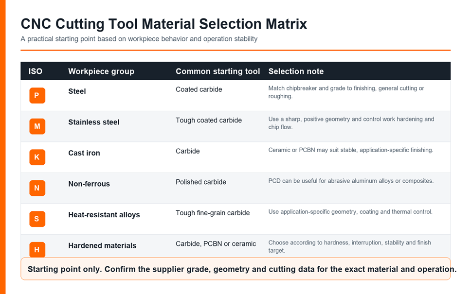
Tool Selection by ISO Workpiece Group
ISO P: Steels
Coated carbide covers a broad range of steel turning, milling and drilling. Finishing grades prioritize wear resistance, while roughing and interrupted operations need more edge strength. Chipbreaker selection is critical because many steels create continuous chips.
ISO M: Stainless Steels
Stainless steels can work-harden and adhere to the cutting edge. A sharp positive geometry, controlled feed and reliable chip evacuation help the edge cut rather than rub. A tougher coated carbide grade is a common starting point, but austenitic, duplex and precipitation-hardening grades require different cutting data.
ISO K: Cast Irons
Cast irons often form shorter chips and can be abrasive. Carbide is widely used. Ceramic or PCBN may be appropriate for stable, high-productivity finishing, but casting skin, interruption and material type influence edge security. See the cast iron CNC machining guide for process-specific considerations.
ISO N: Non-Ferrous Materials
Aluminum, copper, brass and many plastics benefit from sharp tools, polished flutes and generous chip space. Material adhesion and chip welding can damage finish. Abrasive silicon-rich aluminum or composites may justify PCD or diamond-coated tools. Plastics also need heat and clamping control; the polypropylene machining guide gives a polymer example.
ISO S: Heat-Resistant Alloys and Titanium
Nickel alloys and titanium can concentrate heat near the cutting zone and impose high mechanical loads. Use application-specific carbide grades, strong but free-cutting geometry, controlled engagement and reliable coolant delivery. Selected ceramic tools can be productive in suitable nickel-alloy operations, but they require stable conditions.
ISO H: Hardened Materials
Coated carbide can handle lower hardness, interrupted cuts or operations that need toughness. Stable finishing of harder ferrous materials may favor PCBN or selected ceramics. Hardness, allowance, surface integrity and interruption must be reviewed together.
Geometry Controls Cutting Forces and Chip Flow
Rake and Edge Preparation
A positive rake and sharp edge reduce cutting force and can help thin walls, non-ferrous materials and less rigid setups. A honed or chamfered edge improves strength for heavy or interrupted cutting but increases force. The correct balance depends on the material and load.
Flute Count, Helix and Chip Space
More flutes can increase the number of cutting edges and feed capacity, but they leave less chip space. Tools for aluminum and full slots often need generous flutes for chip evacuation. Higher flute counts can suit finishing or materials that produce smaller chips when engagement and coolant are controlled.
Corner Radius and Nose Radius
A larger corner or nose radius can strengthen the edge and improve finish under stable conditions. It also increases radial force and can promote chatter on thin or flexible parts. Radius selection should follow feature geometry, allowance, stability and the required surface.
Chipbreakers
Indexable inserts use chipbreaker geometry to form and direct chips within a defined feed and depth-of-cut range. A chipbreaker used outside its intended range may rub, create long chips or overload the edge. Match roughing, medium and finishing geometries to the actual cut.
Solid Carbide vs Indexable Tooling
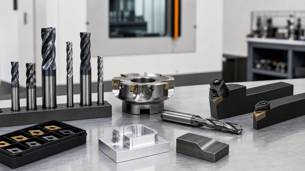
Solid carbide end mills and drills provide accurate geometry, stiffness and access at small diameters. They are useful for complex profiles, pockets, small holes and finishing. When worn, the complete tool is replaced or professionally reconditioned.
Indexable cutters use replaceable inserts. They are common for face milling, shoulder milling, large-diameter drilling and turning. Multiple insert grades and geometries can use the same holder, and only the worn edge is replaced. They require correct insert seating, screw torque and pocket condition.
Choose by operation, diameter, reach, machine power, required accuracy and the economics of edge replacement. A mixed tool list is normal.
Holders, Stickout and Runout
The holder must transmit torque and locate the cutting edge repeatably. Clean contact surfaces before assembly. Do not clamp an end mill on the transition between its shank and flutes. Follow the holder and tool manufacturer’s torque, balance and engagement requirements.
Minimize stickout while maintaining safe clearance. For small tools or fine finishing, measure runout close to the cutting edge when practical. Unequal flute loading can create chatter, size error and premature wear even when the programmed feed appears correct.
Coolant, Lubrication and Chip Evacuation
Coolant strategy is part of tool selection. Flood coolant, through-tool coolant, air blast and minimum-quantity lubrication serve different purposes. Some applications need cooling, some need lubrication, and some prioritize removing chips from the cutting zone.
Inconsistent coolant can create thermal cycling, especially in interrupted milling. Deep holes may require through-tool delivery to clear chips. Aluminum can suffer from chip welding when lubrication and evacuation are poor. A process should not alternate casually between dry and wet cutting without considering the selected tool and operation.
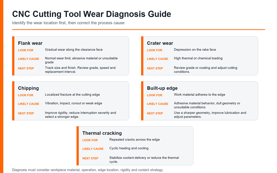
Diagnose Cutting Tool Wear Before Changing Parameters
Flank Wear
Uniform flank wear is a normal tool-life mechanism. Replace the edge before it causes unacceptable size, finish or cutting load. Accelerated flank wear can indicate abrasive material, excessive speed or an unsuitable grade.
Crater Wear
Crater wear appears on the rake face where the chip contacts the tool. It is associated with thermal and chemical loading. A more suitable grade or coating and revised cutting conditions may be needed.
Chipping and Edge Fracture
Chipping points to mechanical instability more often than simple gradual wear. Check runout, holder condition, workholding, entry, interruption, chip recutting and edge strength before only reducing speed.
Built-Up Edge
Built-up edge occurs when work material adheres to the cutting edge. It can change effective geometry, damage finish and break away unpredictably. Sharper geometry, suitable lubrication, a compatible coating or polished surface, and corrected cutting conditions can help.
Thermal Cracking
Repeated cracks can form when the edge experiences strong heating and cooling cycles. Stabilize coolant delivery or change the thermal strategy. Sandvik Coromant’s official turning handbook illustrates common wear patterns including flank wear, crater wear, chipping and built-up edge.
Do not diagnose from sound alone. Photograph the edge, record material, operation, cutting data, tool life, surface result and the exact location of wear. Change one major variable at a time when possible.
How Tooling Affects Tolerance, Finish and Cost
A worn or unstable tool can create taper, oversize holes, burrs and inconsistent surface texture. Tool deflection can leave walls thicker at depth. Built-up edge can smear material. Insert indexing or tool replacement may shift size if offsets and seating are not controlled.
Finishing strategy should define allowance, tool condition, compensation and inspection timing. The CNC surface finish options guide explains how as-machined texture and secondary finishing should be specified.
For production economics, compare acceptable tool life, cycle time, edge cost, change time and scrap. A tool that lasts longer but forces a slower cycle may not reduce total cost. A faster tool that creates unpredictable failure can be worse. Stable, measurable performance is the goal.
A Practical CNC Cutting Tool Selection Workflow
- Confirm the workpiece. Record alloy, temper, hardness, casting condition and any abrasive reinforcement.
- Define the operation. State turning, milling, drilling or threading; roughing or finishing; engagement; reach; and interruption.
- Evaluate stability. Review machine condition, spindle interface, holder, tool diameter, stickout, fixture and workpiece rigidity.
- Set acceptance requirements. Identify dimensional, finish, burr and surface-integrity requirements.
- Choose the tool family. Decide between HSS, solid carbide, indexable carbide, PCD, PCBN or ceramic based on the application window.
- Select grade, coating and geometry. Use the exact tool manufacturer’s application chart and recommended starting data.
- Plan coolant and chip control. Make sure chips can leave the cut and the coolant strategy is stable.
- Prove out safely. Confirm clearance, load and chip behavior under controlled conditions.
- Inspect the first acceptable part. Verify critical features and surface condition.
- Record wear and optimize. Track tool life and failure mode before changing conditions.
Information to Send for a Machining Review
Provide the native CAD model and controlled drawing, material grade and condition, quantities, critical tolerances, surface requirements, heat treatment and expected repeat demand. If a feature has a difficult reach or an internal corner, identify its functional purpose rather than specifying a smaller tool without context.
For a tight-tolerance aluminum example, review the 6061 aluminum CNC machining tolerance guide. Then upload your CAD files for a CNC quote so the process, tooling, workholding and inspection plan can be reviewed together.
Frequently Asked Questions
Is carbide always better than HSS?
No. Carbide offers high stiffness, wear resistance and productivity in many CNC operations. HSS provides greater toughness and can support sharp or complex forms, low-speed work and less rigid conditions. The correct choice follows the complete application.
Should aluminum be machined with coated or uncoated tools?
Many wrought aluminum applications use polished uncoated carbide to reduce adhesion and evacuate chips. Abrasive aluminum alloys, long production runs or special operations may justify PCD or a compatible coating. Confirm the alloy and supplier recommendation.
What is the best coating for stainless steel?
There is no single best coating for every stainless grade and operation. Austenitic, duplex and precipitation-hardening stainless steels behave differently. Choose the substrate, coating, geometry and cutting data as a system.
What causes a CNC end mill to chip?
Common causes include runout, chatter, excessive stickout, unstable workholding, severe entry, chip recutting, an interrupted surface or an edge that is too weak for the load. Inspect the wear location before changing parameters.
When should PCD or PCBN be considered?
PCD is mainly considered for suitable non-ferrous and abrasive materials. PCBN is mainly considered for selected hardened ferrous materials and cast irons. Both require enough stability, production value and material compatibility to justify their cost.
Can a coating repair a poor tool setup?
No. A coating may improve wear, friction or thermal resistance, but it cannot correct excessive runout, weak clamping, blocked chip evacuation or the wrong geometry.