Die casting and CNC machining solve different manufacturing problems. Die casting produces repeatable near-net-shape metal components efficiently once tooling is established, while CNC machining controls the bores, sealing faces, threads, datums and surface requirements that a casting process alone may not reliably achieve.
For recurring aluminum, zinc or magnesium components, combining the two processes can reduce unnecessary material removal and machine time without sacrificing functional accuracy. The correct workflow depends on annual volume, alloy, casting quality, machining allowance, tolerance strategy, inspection method and surface-finish requirements. This guide explains where each process adds value and how to design a robust combined manufacturing route.
Key Takeaways
- Die casting is most valuable when repeat production justifies tooling and the part can be formed close to its final shape.
- CNC finish machining should be reserved for features that control fit, sealing, motion, alignment or assembly.
- CNC machining can improve selected dimensions and surfaces, but it cannot repair internal porosity, shrinkage cavities or cracks.
- The lowest-cost process is determined by total project economics, not by comparing machining time or tooling price alone.
- A reliable quotation requires a 3D CAD model, a 2D drawing, expected production volume, alloy, critical tolerances and inspection requirements.
What Is Die Casting?
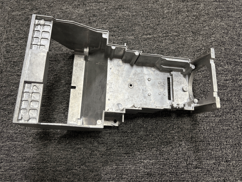
Die casting is a metal-forming process in which molten alloy is injected into a reusable steel die. The metal fills the cavity, solidifies under controlled conditions and is ejected as a near-net-shape component. After casting, runners, gates and flash are removed before secondary operations such as deburring, machining, coating and assembly.
High-pressure die casting is widely used for repeat production because it can create thin walls, ribs, bosses and complex external geometry with good repeatability. The tooling investment is higher than for machining a part directly from stock, but the production cycle can become economical when order volume is sufficient and the design is stable.
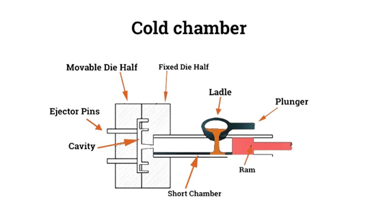
Cold-Chamber Die Casting
In a cold-chamber machine, molten metal is transferred into the shot sleeve for each cycle and then injected into the die. This approach is commonly used for aluminum alloys and other alloys that are not suitable for continuous contact with the injection system.
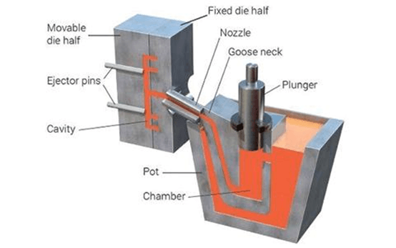
Hot-Chamber Die Casting
In a hot-chamber machine, the injection system is immersed in the molten metal. The process supports fast cycles and is commonly used for zinc alloys and other compatible low-melting-point materials.
What Is CNC Machining?
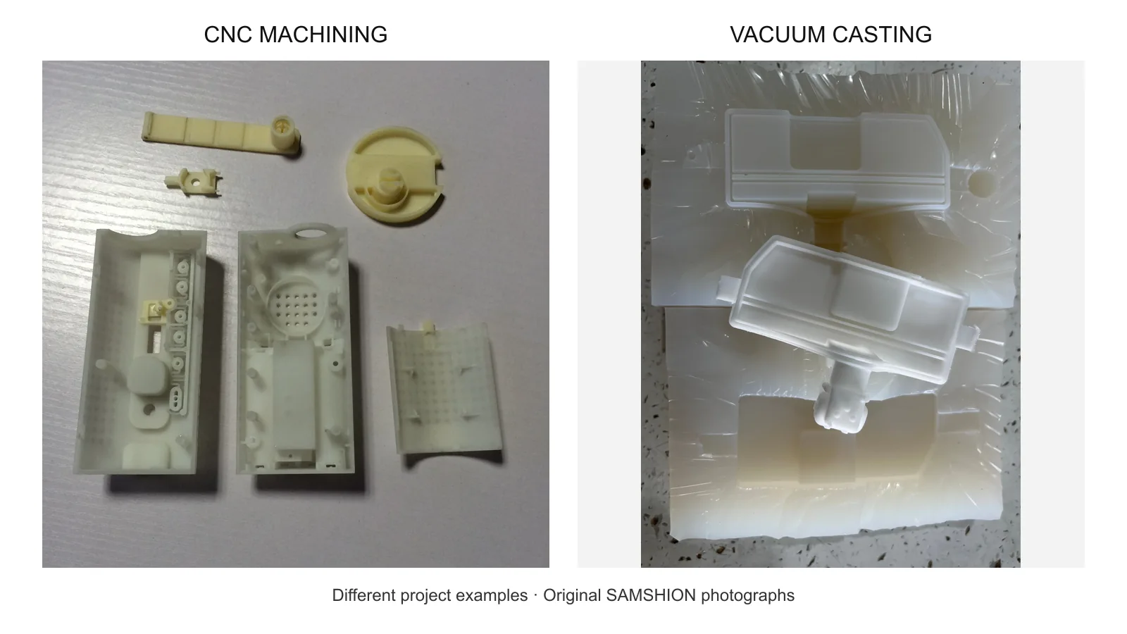
CNC machining is a subtractive process that removes material from a billet, plate, bar, extrusion, forging or casting. Computer-controlled milling and turning equipment follows programmed toolpaths to produce defined geometry and dimensions.
CNC machining can manufacture complete parts from solid stock, especially for prototypes and low-volume production. It can also be used as a secondary process after die casting. In the combined route, the casting provides most of the geometry and CNC machining finishes only the functional features that need tighter control.
Common finish-machining operations on die-cast parts include:
- Milling mounting faces, datum pads and sealing surfaces.
- Boring or reaming bearing seats and alignment holes.
- Drilling and tapping threaded holes.
- Machining O-ring grooves and gasket interfaces.
- Creating slots, pockets or features that cannot be released from the die.
- Removing selected gate, overflow or ejector-pin witness areas.
Why Combine Die Casting and CNC Machining?
The combined process separates the part into two groups of features. Geometry that can be produced repeatably in the die remains as-cast, while function-critical geometry is finish machined. This prevents the project from paying CNC time to remove material that the casting process could have formed directly.
The approach is especially useful for housings, pump bodies, motor components, brackets, gear cases, electronic enclosures, pneumatic components and structural parts with a mixture of complex external geometry and precision interfaces.
A suitable component often includes several of the following conditions:
- Recurring production volume that can justify die tooling.
- A stable design that is unlikely to change after tool release.
- Complex near-net-shape geometry that would require extensive material removal from solid stock.
- A limited number of critical bores, faces, threads or sealing features.
- A practical way to establish stable machining datums on the casting.
- Inspection requirements that can be measured consistently during production.
Die Casting and CNC Machining Workflow
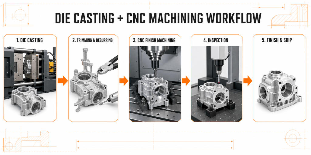
1. Design Review and Process Selection
The project begins with the 3D model, 2D drawing, alloy, production quantity and functional requirements. The engineering team separates as-cast features from machined features and evaluates draft, wall thickness, fillets, gate location, ejection, machining access and inspection access.
At this stage, the team should also compare full CNC machining with die casting plus CNC finishing. Prototype or low-volume demand may favor complete machining, while recurring production with stable geometry may support a tool-based route. A rapid-prototyping phase can be used to verify assembly and function before production tooling is released.
2. Tooling, Sampling and Casting Validation
The die is designed around metal flow, venting, cooling, shrinkage, ejection and tool life. Initial samples are reviewed for dimensional stability, filling, flash, surface condition and internal quality where required. Any machining fixtures should be developed using real sample castings rather than an idealized nominal model alone.
3. Trimming and Deburring
After casting, the runner system, gates, overflows and flash are removed. Deburring prepares the component for handling and machining. The trimming method must avoid distorting thin walls or damaging surfaces that will later be used as machining references.
4. Datum Establishment and CNC Finish Machining
The first machining operation establishes reliable datums. Later operations reference those datums to control the relationship between bores, sealing faces, mounting pads and threaded features. Fixture contact points should be placed on stable regions that can resist clamping without distortion.
Machining allowance must be sufficient to clean up the required surface despite normal casting variation, but excessive allowance increases cutting time, tool wear and the risk of exposing subsurface porosity.
5. Inspection and Functional Testing
Inspection is based on the drawing and control plan. Typical methods include CMM inspection, gauges, surface-roughness measurement, visual inspection and thread verification. Leak-critical components may also require pressure-decay, air-under-water, helium or another agreed leak-test method. The appropriate method depends on the product and acceptance criteria.
6. Surface Treatment, Final Inspection and Shipping
After machining, parts may be cleaned, blasted, conversion coated, painted, powder coated, plated or otherwise finished. Masking requirements for threads, bores, electrical contacts and sealing surfaces must be defined before finishing. Final inspection confirms that finishing has not changed critical dimensions or contaminated functional surfaces.
When Is the Combined Process the Right Choice?
Die casting plus CNC machining is usually worth evaluating when a project has repeat demand, complex external geometry and only selected precision features. The tooling cost can be distributed across the production quantity, while the near-net-shape casting reduces the amount of material removed during machining.
The combined route should be reviewed when:
- The design has reached a stable production stage.
- Annual demand is recurring rather than a one-time order.
- Full machining from solid stock creates high material waste or long cycle time.
- The casting can incorporate ribs, bosses, thin walls or internal passages efficiently.
- Only a controlled group of features needs finish machining.
- The required alloy is compatible with the selected casting process and finishing route.
When Is Full CNC Machining a Better Choice?
Combining processes is not automatically the lowest-cost answer. Full CNC machining may be more suitable when quantities are low, the design is still changing, tooling lead time is unacceptable or the component requires material properties that are better achieved with wrought stock.
Full machining may also be preferred when:
- The expected quantity cannot justify production tooling.
- Multiple design revisions are likely.
- The part requires extensive machining on most surfaces.
- The alloy or heat-treatment requirement is not suitable for conventional high-pressure die casting.
- Very low porosity or structural requirements favor another process route.
- A prototype is needed before production geometry is frozen.
For recurring demand, CNC production machining can also be evaluated with extrusions, forgings and other near-net-shape blanks before a die-casting tool is justified.
Design Guidelines for Die-Cast and CNC-Machined Parts
Separate As-Cast and Machined Requirements
The drawing should identify which surfaces remain as-cast and which surfaces are machined. Applying the same tolerance and surface-finish requirement to the entire part can create unnecessary operations and inspection cost.
Use tighter controls only where they support fit, sealing, alignment, bearing performance, electrical contact or another defined function. Cosmetic expectations should be documented separately from dimensional requirements.
Establish Functional Datums
Choose datums that represent how the part assembles and functions. The machining sequence should establish stable primary, secondary and tertiary references before producing dependent features. Avoid using an irregular parting line, a small ejector witness or an unstable thin wall as the main machining reference.
Control Machining Allowance
Machining allowance must account for casting variation, tool wear, distortion and fixture repeatability. Too little allowance can leave incomplete cleanup. Too much allowance increases machine time, cutting load and the chance of exposing subsurface pores.
Allowance should therefore be assigned by feature rather than added uniformly to every surface. Critical sealing faces may require complete cleanup, while nonfunctional exterior surfaces can often remain as-cast.
Maintain Uniform Wall Thickness
Uniform walls support more consistent filling and solidification. Abrupt transitions and isolated heavy sections can increase the risk of shrinkage and distortion. Where additional stiffness is needed, ribs and gradual transitions are often more effective than adding a large solid mass.
Include Draft, Fillets and Radii
Draft helps the casting release from the die. Fillets and radii improve metal flow, reduce stress concentration and avoid fragile sharp tool features. Exact values depend on alloy, wall depth, surface requirement and die construction, so they should be confirmed during DFM review.
The North American Die Casting Association’s die-casting design guidance also identifies uniform wall thickness, sufficient draft and fillets or radii as fundamental design practices for die-cast components.
Review Gates, Overflows and Ejector Locations
Gate, overflow and ejector locations affect filling, trimming, appearance and machining access. They should not interfere with sealing faces, datums or cosmetic surfaces. If a gate witness must be machined away, the required operation and inspection method should be included in the quotation.
Avoid Casting Precision Threads Where Reliability Matters
Threads, threaded inserts and fastener features require individual review. Machined threads generally provide better dimensional control than cast threads. Thread depth, engagement, insert installation, pull-out load and corrosion conditions should be specified according to the application.
Use GD&T to Protect Function
Geometric dimensioning and tolerancing can control the relationship between machined and as-cast features without applying unnecessarily tight plus/minus tolerances everywhere. Datum references, position, profile, flatness, perpendicularity and runout should be chosen according to assembly function and measurable inspection methods.
Materials for Die Casting and Post-Machining
Material selection must consider casting behavior, strength, corrosion, weight, machinability, thermal performance, surface finishing and cost. Review the available manufacturing materials before finalizing the drawing.
Aluminum Die-Casting Alloys
Aluminum die-casting alloys provide a useful balance of weight, corrosion resistance, thermal performance and mechanical properties. Common high-pressure die-casting selections include A380 and ADC12, subject to regional standards and project requirements.
Aluminum-silicon die-casting alloys are machinable, but silicon content influences tool wear and surface appearance. High-silicon castings may also show darker or less uniform color after anodizing than wrought aluminum.
Zinc Die-Casting Alloys
Zinc alloys such as Zamak 3 and Zamak 5 support detailed features, good dimensional repeatability and efficient hot-chamber production. Zinc components can be machined, plated, painted or otherwise finished when the product requires precision interfaces or cosmetic surfaces.
Magnesium Die-Casting Alloys
Magnesium alloys such as AZ91D are selected when low weight is important. Machining and finishing require suitable process controls, clean handling and attention to corrosion protection. Alloy, coating and environmental requirements should be confirmed together.
Important Note About A356
A356 is more commonly associated with gravity, low-pressure or permanent-mold casting than conventional high-pressure die casting. If A356 is specified, the quotation and technical content should clearly identify the actual casting process instead of grouping it with A380 or ADC12 high-pressure die-casting alloys.
Tolerances and Surface Roughness
There is no single tolerance that applies to every die-cast and machined component. Achievable results depend on feature size, alloy, tool condition, die temperature, parting line, ejector system, datum strategy, machining setup and inspection method.
For formal guidance covering alloy data, coordinate dimensioning, GD&T and quality assurance, refer to the NADCA Product Specification Standards overview.
The drawing should distinguish among:
- As-cast dimensions controlled by the die and casting process.
- Machined dimensions controlled by cutting tools and fixtures.
- Relationships between machined and as-cast features.
- Cosmetic surfaces that require an approved visual standard.
- Critical characteristics that require documented inspection.
Do not apply a blanket claim such as +/-0.005 mm or +/-0.1 mm to the entire component. Critical tolerances should be confirmed feature by feature during drawing review.
Surface-Roughness Requirements
Surface roughness should be specified only where it supports sealing, bearing, appearance, friction or another defined function. Requiring Ra 0.8 micrometers or better across an entire casting can add unnecessary machining and inspection time.
Review the available CNC surface-finish options before assigning finish requirements. A machined sealing face, a bearing bore and an exterior cosmetic wall do not normally require the same specification.
What CNC Machining Can - and Cannot - Correct
CNC finish machining can remove selected flash, establish reliable datums, improve flatness on chosen mating faces and produce accurate holes, threads, grooves and sealing surfaces. These operations improve assembly consistency because function-critical features are referenced to controlled machining setups rather than relying only on as-cast dimensions.
CNC machining cannot repair internal porosity, shrinkage cavities or cracks. Removing the casting skin may expose subsurface pores that were not visible before machining. Casting design, metal flow, venting, vacuum, process parameters and solidification control must address the source of these defects.
NADCA’s porosity guidance treats porosity reduction as a combined program of understanding causes, controlling process parameters, improving casting design, and predicting and measuring the resulting porosity level.
Leak-critical or highly loaded components therefore require a defined quality-assurance and inspection plan. Depending on the risk, the plan may include X-ray or CT inspection, pressure or leak testing, dye-penetrant inspection, impregnation where appropriate and agreed rejection criteria.
Surface Finishing After Casting and Machining
The correct finish depends on alloy, environment, appearance and functional requirements. Options may include as-cast cleaning, shot blasting, tumbling, conversion coating, painting, powder coating, plating and selected polishing.
High-silicon aluminum die-casting alloys such as A380 and ADC12 may produce darker, less uniform anodized colors than wrought alloys such as 6061. If cosmetic consistency is critical, confirm the alloy, porosity level, surface preparation, masking and approved appearance sample before production. Powder coating, conversion coating or painting may provide more predictable cosmetic results for some die-cast parts.
Finishing instructions should identify:
- Surfaces that must remain electrically conductive.
- Threads, bores and sealing faces that require masking.
- Acceptable color, gloss and texture variation.
- Areas where rack, fixture or contact marks are permitted.
- Coating thickness where it affects fit or assembly.
- Post-finish inspection requirements.
Cost Drivers for Die Casting Plus CNC Machining
The combined route is most economical when production volume is high enough to justify tooling and only a limited percentage of the casting requires precision machining. Cost savings come from near-net-shape geometry, reduced material removal and machining only the features that control fit or function.
The complete cost model should include:
- Die design, die manufacture and maintenance.
- Number of cavities and expected tool life.
- Alloy price and casting weight.
- Machine size, cycle time and production yield.
- Trimming, deburring and cleaning.
- Number of CNC setups and machining cycle time.
- Fixture design and fixture replacement.
- Cutting tools and tool wear.
- Inspection frequency and reporting.
- Leak testing, impregnation or special validation.
- Surface finishing, masking and packaging.
It is not professional to promise a fixed percentage saving without reviewing the actual part. Samshion compares full CNC machining, die casting plus CNC finishing and other near-net-shape routes during DFM review before recommending a production method.
Full CNC Machining vs. Die Casting Plus CNC Finishing
Choose Full CNC Machining When
- The project is a prototype or low-volume order.
- The design is likely to change.
- Tooling investment or lead time is not justified.
- Wrought material properties are required.
- Most surfaces need machining.
- Production must start before a die can be manufactured.
Evaluate Die Casting Plus CNC Finishing When
- The design is stable and demand is recurring.
- The casting can create most geometry close to final shape.
- Only selected interfaces require precision machining.
- The tooling investment can be distributed across production volume.
- Casting, machining, inspection and finishing requirements can be planned as one controlled process.
Quality Control for Die-Cast and Machined Parts
A combined process needs controls for both the casting and machining stages. Inspecting only the final CNC dimensions is not enough if casting variation can affect porosity, distortion, coating or long-term function.
A practical control plan may include:
- Verification of alloy and material certificates.
- First-article dimensional inspection.
- CMM inspection of critical datums and feature relationships.
- In-process gauges for repeat characteristics.
- Thread gauges and functional assembly checks.
- Surface-roughness measurement where specified.
- Visual standards for flash, porosity exposure and coating appearance.
- Leak or pressure testing for fluid-handling components.
- Traceability of casting lot, machining batch and inspection records.
Inspection frequency should reflect feature risk, process capability, production volume and customer requirements. The drawing and purchase documentation should state whether a dimensional report, CMM report, material certificate, coating certificate or other record is required.
From Quote to Production Parts
Step 1: Upload Your Files
Provide the 3D CAD model, 2D drawing, target quantity, alloy, surface treatment and required delivery schedule. Identify all critical-to-function dimensions, leak-test requirements and cosmetic areas.
Step 2: Receive DFM Feedback
Samshion reviews process selection, draft, wall thickness, radii, machining allowance, datum strategy, tool access, inspection access and finishing requirements. Questions are resolved before tooling or fixtures are released.
Step 3: Confirm the Manufacturing Route
The team compares full CNC machining with die casting plus CNC finishing and, where appropriate, extrusion, forging or other near-net-shape alternatives. The quotation identifies tooling, samples, production operations, inspection and finishing.
Step 4: Validate Samples
Initial samples are reviewed against the drawing and approved requirements. Machining fixtures and inspection methods are confirmed using representative castings.
Step 5: Start Controlled Production
Casting, trimming, machining, inspection and finishing follow the approved route. Process records and traceability are maintained according to the project requirements.
Step 6: Final Inspection and Delivery
Final parts are inspected, protected and packaged for shipment. Required reports and certificates are supplied with the order.
Frequently Asked Questions
Is Die Casting More Accurate Than CNC Machining?
The processes should not be compared with one universal accuracy number. Die casting can repeat complex near-net-shape geometry efficiently, while CNC machining can hold tighter control on selected features. The combined route uses each process where it provides the greatest value.
Can CNC Machining Remove Porosity From a Die Casting?
No. CNC machining may remove surface material, but it cannot repair internal gas porosity, shrinkage cavities or cracks. Machining may expose subsurface pores. Porosity must be controlled through casting design, tooling and process parameters, then verified with the appropriate inspection or leak test.
Which Features Should Be CNC Machined After Die Casting?
Typical candidates include bearing bores, sealing faces, datum pads, mounting interfaces, threads, precision holes and grooves. Features should be selected according to function rather than machining every visible surface.
How Much Machining Allowance Should Be Added?
There is no universal value. Allowance depends on casting size, alloy, local variation, datum strategy, cleanup requirement and machining process. It should be defined feature by feature during DFM review.
Can Aluminum Die Castings Be Anodized?
They can be anodized, but high-silicon die-casting alloys may show darker or less uniform cosmetic results than wrought aluminum. Confirm alloy, preparation and an approved appearance sample before selecting anodizing for a cosmetic surface.
When Does Die Casting Plus CNC Machining Become Cost-Effective?
The answer depends on tooling investment, production quantity, casting yield, part weight, machining area, number of setups and inspection requirements. A total-cost comparison is more reliable than using a fixed volume threshold.
Do You Need Both a 3D Model and a 2D Drawing?
The 3D model defines geometry, while the 2D drawing communicates tolerances, datums, surface finish, threads, coating, inspection and other requirements. Providing both reduces quotation assumptions and supports a more reliable manufacturing plan.
What Information Is Needed for a Quote?
Provide CAD files, drawings, alloy, expected quantity, annual demand, critical tolerances, surface treatment, inspection reports, leak-test requirements, cosmetic standards and target delivery. This information allows the engineering team to compare the available process routes.
Request a Die Casting and CNC Machining Review
Send your 3D CAD model, 2D drawing, alloy, annual volume, critical tolerances, leak-test requirements and surface-finish specification. Samshion’s engineering team will compare full CNC machining with a die-cast-plus-machined route and identify the features that should remain as-cast or be finish machined.