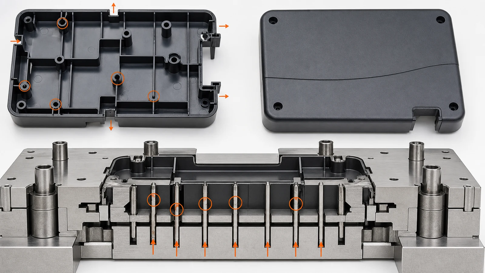
A molded part must release from cores and cavity surfaces without permanent deformation, whitening, cracks or unacceptable witnesses. Ejector pins concentrate force into small circular areas, so their size, number and location must match part stiffness and actual release resistance.
Marks are not solved only by polishing pins flush. Draft, undercuts, shrinkage, cooling balance, surface texture, venting and timing all influence how much force the ejection system must deliver.
Scope, Search Intent and Technical Boundary
This article covers pin-based part ejection and the visible or dimensional evidence it can create. It does not replace a complete tool-ejection design for sleeves, stripper plates or air assistance. For broader geometry and specification guidance, use the manufacturing materials guide alongside this feature-level discussion. For an additional authoritative reference, consult BASF injection-molding problems causes and solutions.
Designers, quality teams and sourcing personnel can use this workflow to expose assumptions about injection molding ejector pin marks before material is released.
Key Takeaways
- Place ejectors on supported, noncritical surfaces where load can spread.
- Use enough draft and avoid hidden release resistance.
- Balance pin force around cores, ribs and deep walls.
- Define acceptable witness against the correct cosmetic zone.
- Confirm ejection after the part reaches a stable release condition.
Understand What an Ejector Mark Reveals
A raised, depressed, white or cracked witness points to different combinations of pin fit, part temperature, local stiffness and release force. For the corresponding manufacturing decision and capability context, consult SAMSHION’s injection molding services.
Place Pins on Supported Geometry
Bosses, ribs and structural pads can provide support, while thin cosmetic walls and sealing faces are usually poor pin locations.
Reduce Release Force before Adding More Force
Draft, polished pull direction, controlled texture, correct mold temperature and elimination of undercuts can reduce the load required. For the corresponding manufacturing decision and capability context, consult SAMSHION’s overmolding production guide.
Balance Cooling and Ejection Timing
An overly hot or unevenly cooled part is more vulnerable to pin indentation and distortion even when the layout appears adequate. For the corresponding manufacturing decision and capability context, consult SAMSHION’s injection molding shrinkage guide.
Define Cosmetic and Dimensional Acceptance
The drawing or appearance standard should identify zones, viewing conditions and whether local height, sink or whitening is permitted. For the corresponding manufacturing decision and capability context, consult SAMSHION’s surface finishing services.
Engineering Variables to Confirm Before Quotation
Draft angle and texture direction
Confirm draft angle and texture direction before quotation. Evaluate it against release force, supported geometry, surface class and cooled-part dimensions. Record the agreed value, part condition and acceptance stage on the controlled drawing or DFM record so mold setup, molding process and quality inspection use the same requirement.
Part shrinkage onto cores
Confirm part shrinkage onto cores before quotation. Evaluate it against release force, supported geometry, surface class and cooled-part dimensions. Record the agreed value, part condition and acceptance stage on the controlled drawing or DFM record so mold setup, molding process and quality inspection use the same requirement.
Pin diameter, count, location and projection
Confirm pin diameter, count, location and projection before quotation. Evaluate it against release force, supported geometry, surface class and cooled-part dimensions. Record the agreed value, part condition and acceptance stage on the controlled drawing or DFM record so mold setup, molding process and quality inspection use the same requirement.
Wall, rib and boss stiffness near each pin
Confirm wall, rib and boss stiffness near each pin before quotation. Evaluate it against release force, supported geometry, surface class and cooled-part dimensions. Record the agreed value, part condition and acceptance stage on the controlled drawing or DFM record so mold setup, molding process and quality inspection use the same requirement.
Mold temperature and release timing
Confirm mold temperature and release timing before quotation. Evaluate it against release force, supported geometry, surface class and cooled-part dimensions. Record the agreed value, part condition and acceptance stage on the controlled drawing or DFM record so mold setup, molding process and quality inspection use the same requirement.
Cosmetic zone and dimensional tolerance
Confirm cosmetic zone and dimensional tolerance before quotation. Evaluate it against release force, supported geometry, surface class and cooled-part dimensions. Record the agreed value, part condition and acceptance stage on the controlled drawing or DFM record so mold setup, molding process and quality inspection use the same requirement.
Failure Modes and Root-Cause Diagnosis
A circular pin witness becomes visible after painting
When a circular pin witness becomes visible after painting, inspect draft, texture direction, core retention, local stiffness, pin contact and cooling balance. Compare the affected part with a controlled reference and change one suspected variable at a time. Retain the failed part, process record and measurement evidence until the root cause is confirmed.
A deep core holds the part and one side whitens during ejection
When a deep core holds the part and one side whitens during ejection, inspect draft, texture direction, core retention, local stiffness, pin contact and cooling balance. Compare the affected part with a controlled reference and change one suspected variable at a time. Retain the failed part, process record and measurement evidence until the root cause is confirmed.
Thin geometry distorts because pin force is unbalanced
When thin geometry distorts because pin force is unbalanced, inspect draft, texture direction, core retention, local stiffness, pin contact and cooling balance. Compare the affected part with a controlled reference and change one suspected variable at a time. Retain the failed part, process record and measurement evidence until the root cause is confirmed.
A pin sits proud or recessed and embosses the surface
When a pin sits proud or recessed and embosses the surface, inspect draft, texture direction, core retention, local stiffness, pin contact and cooling balance. Compare the affected part with a controlled reference and change one suspected variable at a time. Retain the failed part, process record and measurement evidence until the root cause is confirmed.
Process Controls for a Repeatable Result
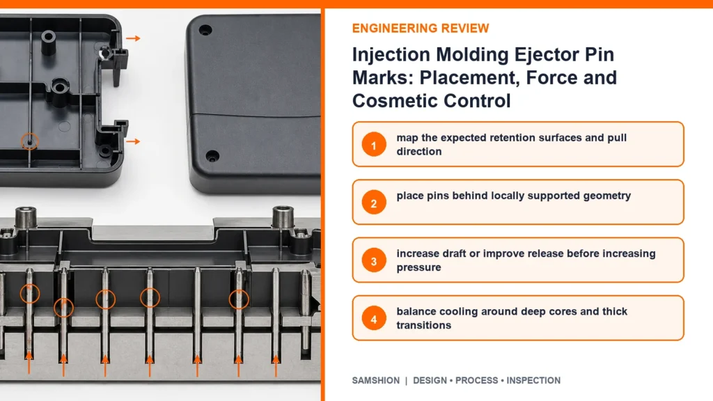
Map the expected retention surfaces and pull direction
Implement map the expected retention surfaces and pull direction as a documented process control. Record pin layout, draft, mold temperature, cooling time, ejection settings and cavity number. Verify the control on the first article, then define the check frequency and reaction limit for repeat production.
Place pins behind locally supported geometry
Implement place pins behind locally supported geometry as a documented process control. Record pin layout, draft, mold temperature, cooling time, ejection settings and cavity number. Verify the control on the first article, then define the check frequency and reaction limit for repeat production.
Increase draft or improve release before increasing pressure
Implement increase draft or improve release before increasing pressure as a documented process control. Record pin layout, draft, mold temperature, cooling time, ejection settings and cavity number. Verify the control on the first article, then define the check frequency and reaction limit for repeat production.
Balance cooling around deep cores and thick transitions
Implement balance cooling around deep cores and thick transitions as a documented process control. Record pin layout, draft, mold temperature, cooling time, ejection settings and cavity number. Verify the control on the first article, then define the check frequency and reaction limit for repeat production.
Maintain pin fit and flush condition
Implement maintain pin fit and flush condition as a documented process control. Record pin layout, draft, mold temperature, cooling time, ejection settings and cavity number. Verify the control on the first article, then define the check frequency and reaction limit for repeat production.
Approve witnesses using representative molded samples
Implement approve witnesses using representative molded samples as a documented process control. Record pin layout, draft, mold temperature, cooling time, ejection settings and cavity number. Verify the control on the first article, then define the check frequency and reaction limit for repeat production.
Inspection Strategy and Acceptance Evidence
Witness height or depression in critical areas
Evaluate witness height or depression in critical areas using controlled lighting, depth or height measurement, dimensional inspection after cooling and cavity comparison. State the part condition, datum or reference, acceptance limit and actual result. Keep the result traceable to cavity, molding lot and approved appearance sample.
Whitening, cracks and drag direction
Evaluate whitening, cracks and drag direction using controlled lighting, depth or height measurement, dimensional inspection after cooling and cavity comparison. State the part condition, datum or reference, acceptance limit and actual result. Keep the result traceable to cavity, molding lot and approved appearance sample.
Flatness or profile after complete cooling
Evaluate flatness or profile after complete cooling using controlled lighting, depth or height measurement, dimensional inspection after cooling and cavity comparison. State the part condition, datum or reference, acceptance limit and actual result. Keep the result traceable to cavity, molding lot and approved appearance sample.
Pin pattern consistency across cavities
Evaluate pin pattern consistency across cavities using controlled lighting, depth or height measurement, dimensional inspection after cooling and cavity comparison. State the part condition, datum or reference, acceptance limit and actual result. Keep the result traceable to cavity, molding lot and approved appearance sample.
Appearance under the approved lighting and viewing standard
Evaluate appearance under the approved lighting and viewing standard using controlled lighting, depth or height measurement, dimensional inspection after cooling and cavity comparison. State the part condition, datum or reference, acceptance limit and actual result. Keep the result traceable to cavity, molding lot and approved appearance sample.
Cost, Lead Time and Quotation Transparency
Extra ejector components and mold machining
Treat extra ejector components and mold machining as a separate quotation driver when it changes tool construction, cycle time, surface finishing, sampling or corrective tool work. State what is included, the assumed acceptance evidence and which design or process change would require requotation.
Texture or polish changes to improve release
Treat texture or polish changes to improve release as a separate quotation driver when it changes tool construction, cycle time, surface finishing, sampling or corrective tool work. State what is included, the assumed acceptance evidence and which design or process change would require requotation.
Longer cooling required before safe ejection
Treat longer cooling required before safe ejection as a separate quotation driver when it changes tool construction, cycle time, surface finishing, sampling or corrective tool work. State what is included, the assumed acceptance evidence and which design or process change would require requotation.
Cosmetic rework or tool correction after trials
Treat cosmetic rework or tool correction after trials as a separate quotation driver when it changes tool construction, cycle time, surface finishing, sampling or corrective tool work. State what is included, the assumed acceptance evidence and which design or process change would require requotation.
A Practical Engineering Review Sequence
First, mark the pull direction, deep cores, textured surfaces, cosmetic zones and functional datums on the part drawing. This separates release risk from appearance acceptance before ejector locations are approved.
Second, review draft, shrinkage, local stiffness and the proposed ejector pattern together. Place pins on supported geometry, balance force around retained features and verify that pin faces are flush with the intended mold surface.
Finally, approve cooled samples by cavity. Record the viewing condition, witness-mark limit, deformation limit and measurement timing so production decisions do not rely on an undefined visual opinion.
RFQ and DFM Checklist
- 3D model and controlled 2D drawing with material and shrinkage assumptions
- Pull direction, draft values, texture callouts and deep-core identification
- Cosmetic-zone map with permitted ejector-mark size, depth or visibility
- Critical dimensions and the required time after molding before inspection
- Expected annual quantity, mold life and number of cavities
- Color, gloss, painting or coating requirements that can reveal pin witnesses
- Known ejection failures, approved samples and mating-part information
Frequently Asked Questions
Are ejector pin marks always defects?
A small controlled witness may be normal on a noncosmetic surface; acceptance must be defined. Confirm the project-specific answer from the controlled drawing and the actual material condition.
Can higher ejection pressure solve sticking?
It can increase damage if the root cause is draft, texture, cooling or an undercut. Confirm the project-specific answer from the controlled drawing and the actual material condition.
Should ejectors be placed behind bosses?
Often this gives support, but boss geometry, sink and surrounding walls still need review. The general rule does not replace a feasibility review of the complete geometry and acceptance method.
Why do marks appear after painting?
Coatings and reflected light can reveal local height and texture changes that were subtle on raw plastic. Supplier and customer should agree the feature definition before production begins.
Can air ejection replace pins?
Air can assist some geometries, but the complete tool and safety strategy must be designed for it. The general rule does not replace a feasibility review of the complete geometry and acceptance method.
Get an Engineering Review
Upload the native CAD model, controlled drawing, material specification, quantity and required finish for a project-specific review of injection molding ejector pin marks.
For a review of injection molding ejector pin marks, send the native CAD model, controlled drawing, material specification, quantity, finishing route and required acceptance records. SAMSHION’s engineering team can return project-specific DFM questions and documented quotation assumptions before production begins. When the model and drawing are ready, use upload your part for mold DFM and include the material, quantity, finish and inspection requirements.