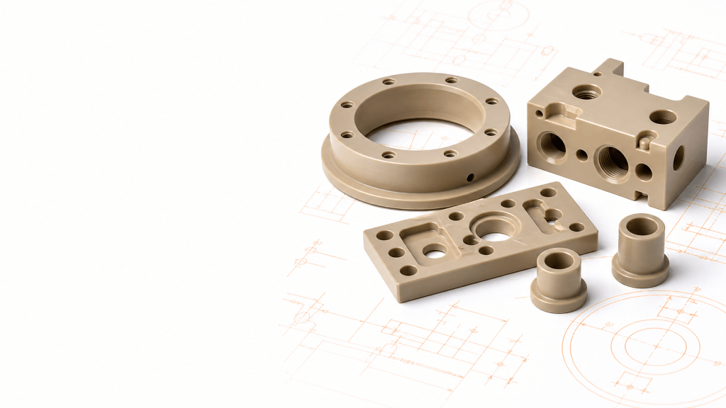
PEEK CNC machining is often selected when a project needs high-temperature performance, chemical resistance, electrical insulation or a strong engineering polymer without injection-mold tooling. The material can be milled, turned, drilled and threaded using conventional CNC equipment, but a reliable result depends on more than choosing “PEEK” in a material list.
The resin grade, stock-shape manufacturing route, reinforcement, thermal history, feature geometry and inspection temperature all influence the finished part. A tolerance that is practical on a short, thick unfilled PEEK component may be unstable or unnecessarily expensive on a thin, fiber-filled housing. Likewise, an annealing cycle that helps one high-temperature application may add time, shrinkage or distortion to a part that did not need it.
This guide explains how engineers should specify, design, quote and inspect CNC-machined PEEK parts. It also separates general guidance from requirements that must come from the selected material supplier, drawing and application.
Quick Answer: Is PEEK Suitable for CNC Machining?
Yes. PEEK stock shapes are routinely machined into prototypes, fixtures and end-use components. Unfilled grades generally machine well with sharp tools and controlled heat. Glass-filled, carbon-filled and bearing grades can be more abrasive, so tool material and tool-life planning become more important.
For a dependable quotation, provide the exact grade or approved equivalent, the required stock-shape certification, a 3D CAD model, a 2D drawing, critical tolerances, surface requirements, quantity, operating temperature and any cleanliness or traceability requirements. If the grade is not yet fixed, identify the functional need instead of asking a supplier to assume that every PEEK grade is interchangeable.
For manufacturing support across engineering plastics, review our CNC machining services and manufacturing materials guide.
What Is PEEK?
Polyetheretherketone, commonly abbreviated as PEEK, is a semi-crystalline high-performance thermoplastic in the PAEK family. It is used where conventional plastics may not provide the required combination of temperature capability, chemical resistance, wear behavior, electrical performance and mechanical retention.
Those advantages do not make PEEK a universal replacement for metal or a standard commodity plastic. Properties depend on the specific grade, test method, temperature, environment and manufacturing route. Machined stock-shape properties can also differ from apparently similar injection-molded parts because crystallinity, fiber orientation and thermal history are not the same.
PEEK should therefore be selected from a current supplier datasheet and application requirements. Do not copy a single strength, temperature or chemical-resistance value into a drawing without confirming its conditions and relevance.
Select the PEEK Grade Before Quoting
“PEEK” alone is not a complete material specification. The grade changes machinability, stiffness, wear behavior, thermal expansion, color, certification and cost. It can also determine whether the finished part is permitted in a regulated application.
Unfilled PEEK
Unfilled PEEK is commonly selected for electrical insulation, chemical service and components that need a balance of toughness and machinability. It is typically less abrasive to cutting tools than fiber-reinforced grades. It can still move when heat or internal stress is released, especially in thin or heavily pocketed geometry.
Glass-Filled PEEK
Glass reinforcement can increase stiffness and reduce thermal expansion in selected directions, but it also makes machining more abrasive. Fiber orientation and the direction in which the part is cut from the stock shape can affect dimensional behavior and surface condition. Sharp carbide may be appropriate for limited work, while longer production runs may justify more wear-resistant tooling after process trials.
Carbon-Filled PEEK
Carbon-filled grades are selected for increased stiffness, lower thermal expansion or other application-specific properties. They are also abrasive and can expose fibers at a machined surface. Tool wear, edge quality, particulate control and surface acceptance criteria should be agreed before production.
Bearing and Wear Grades
Bearing grades can include carbon fiber, graphite, PTFE or other modifiers. They are formulated for friction and wear performance rather than simply being “stronger PEEK.” The modifier package affects machining behavior and may affect bonding, sealing, cleanliness or regulatory suitability.
Medical and Implant Grades
General industrial PEEK must not be described as implant grade. A medical or implantable project requires the exact approved material designation, lot traceability, applicable standards, biocompatibility strategy, manufacturing controls and device-specific regulatory evidence. FDA recognition of ASTM F2026 does not mean that any beige PEEK stock or any machined PEEK component is automatically approved for implantation.
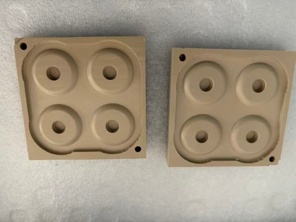
PEEK Grade Selection Table
|
Grade family |
Common reason to specify it |
Machining concern |
What to put on the RFQ |
|
Unfilled PEEK |
Balanced properties, insulation, chemical service |
Heat, burrs, stress release in thin geometry |
Manufacturer, grade, color, stock form and certificate level |
|
Glass-filled PEEK |
Higher stiffness or lower expansion for the application |
Abrasive fibers, edge quality, orientation effects |
Filler percentage, grade, stock orientation and surface criteria |
|
Carbon-filled PEEK |
Stiffness, dimensional behavior or wear performance |
Tool wear, exposed fibers and particulate control |
Exact compound, fiber content, cleanliness and inspection plan |
|
Bearing grade |
Low friction or wear performance |
Modifier-dependent surface and chip behavior |
Exact compound and mating surface or lubrication conditions |
|
Medical or implant grade |
Device-specific regulated use |
Traceability, contamination and validation |
Approved grade, standard, lot traceability and regulatory requirements |
Why Machining PEEK Requires Process Control
Heat Builds at the Cutting Zone
Polymers conduct heat less effectively than metals. A dull tool, rubbing cut, excessive recutting of chips or poor coolant strategy can raise local temperature. The result may be dimensional drift, smeared material, burrs, surface damage or a part that changes after unclamping.
Heat control is achieved through a combination of sharp geometry, appropriate chip load, adequate chip evacuation, limited tool engagement and a coolant or air strategy compatible with the material and end-use cleanliness requirements. A blanket instruction such as “always machine PEEK slowly” is not reliable. Parameters must be developed for the grade, tool, diameter, engagement, machine and feature.
Stock Shapes Contain a Thermal History
Extruded, compression-molded and other stock shapes are not identical. They may have different stress distributions, crystallinity and properties through the section. Removing a large volume from one side can release residual stress and allow the workpiece to bow or twist.
The machining plan should preserve balanced stock where practical. Roughing both sides, alternating faces and leaving finishing allowance can reduce asymmetric stress release. Thick stock with a thin final wall deserves special review.
PEEK Is More Flexible Than Metal
PEEK should not be clamped as if it were aluminum or steel. Excessive vise, jaw or fixture pressure can distort the workpiece during machining. The part may appear correct while restrained and then move after release.
Use broad, clean contact areas and enough support near the cutting zone. Soft jaws, custom nests, sacrificial supports or low-force vacuum fixtures may be useful, but the fixture must resist cutting load without crushing or bowing the part. Inspection should occur in an unrestrained state unless the drawing defines a functional restraint condition.
Reinforced Grades Wear Tools Faster
The term “PEEK” does not by itself justify diamond tooling, but glass- and carbon-filled grades can accelerate wear. A process that works for several unfilled prototypes may lose edge quality during a longer reinforced-grade run. Monitor size, burr formation and surface texture as tool life progresses. For abrasive compounds or repeat production, evaluate coated carbide, PCD or another tool recommended by the tooling supplier.
Tooling and Cutting Strategy
Use Sharp, Positive Cutting Geometry
The cutting edge should shear the polymer rather than rub it. Sharp carbide tooling is a practical starting point for many unfilled PEEK milling and turning operations. Keep tools dedicated and clean when surface contamination matters. Replace a worn edge before compensating for it with more heat or pressure.
Choose Parameters From the Actual Setup
Published speed and feed tables are starting ranges, not finished process instructions. Tool diameter, flute count, radial engagement, axial depth, stock rigidity, grade and coolant all interact. Establish parameters with a controlled trial, then document the validated window for repeat work.
The Victrex finishing guide distinguishes unfilled from reinforced material and provides manufacturer starting guidance. Use the current guide for the selected resin family, then confirm the result on the actual stock shape.
Remove Chips Instead of Recutting Them
Recut chips add heat and can mark a finished surface. Use air, vacuum or compatible coolant to clear the cutting zone. If fluid is used, verify that it is permitted by the material supplier and the final application. Medical, vacuum, semiconductor, food-contact and bonding applications may require controlled fluids and validated cleaning rather than a general-purpose shop coolant.
Plan Roughing and Finishing Separately
Rough the component with enough allowance for relaxation and inspection. Allow the workpiece to return to a stable temperature before final sizing. Use a sharp finishing tool and avoid a light pass that only rubs the surface. Very thin features may need staged roughing, support or an intermediate stress-management step.
For milled pockets, sealing faces and multi-axis access, see our CNC milling capabilities.
Is Annealing Always Required?
No. Secondary annealing is not automatically required for every CNC-machined PEEK part. The decision depends on the stock condition, material supplier guidance, amount and symmetry of material removal, required dimensional stability, wall thickness and service temperature.
Victrex states that secondary annealing is unnecessary for many applications, while some applications use annealing to change crystallinity, remove thermal history, reduce stress or limit dimensional change at high temperature. If annealing is required for a machined part, it should normally be completed before the final machining step. Ensinger likewise advises that intermediate annealing can help when heavy machining or tight geometry creates a distortion risk.
Do not invent a universal oven cycle. Heating rate, soak temperature, hold time, support and cooling rate must come from the exact material and stock-shape supplier. Annealing can cause shrinkage or warpage if it is poorly planned. A useful sequence for a demanding part is:
- Confirm the grade, stock form and supplier heat-treatment guidance.
- Rough-machine symmetrically and leave measured finish allowance.
- Check the unrestrained part for movement.
- Apply an approved intermediate anneal only when the risk assessment requires it.
- Let the workpiece stabilize, re-establish datums and complete finish machining.
- Inspect at the defined temperature and restraint condition.
PEEK Machining Design Guide
Walls and Ribs
Avoid thin walls that stand far above their support or surround a deep pocket. A single universal minimum wall is not responsible engineering because stability depends on height, span, reinforcement, tool access and tolerance. Make nonfunctional walls thicker where packaging allows, add ribs with gradual transitions and identify which wall is truly critical.
Internal Corners
Internal milled corners have a radius. Specify the largest acceptable radius and allow clearance for the mating part. A larger corner radius permits a more rigid tool and reduces machining time. If a sharp corner is functionally necessary, identify whether it can be made by another operation and limit it to the critical location.
Deep Pockets
Deep pockets increase tool reach, evacuation difficulty and heat exposure. Reduce depth, open one side, add access or divide the component when possible. If a deep cavity is unavoidable, use generous internal radii and allow room for the selected tool path.
Holes and Threads
Blind holes need drill-tip allowance and chip space. Deep small-diameter holes may require staged drilling, pecking or specialized tooling. Thread engagement should be based on load and grade rather than copied from a metal part. Threaded inserts may be more reliable when a joint will be assembled repeatedly or highly loaded.
Sealing and Bearing Surfaces
Define the function rather than requesting an unexplained “perfect finish.” Specify surface roughness, flatness, circularity or profile only where the interface needs it. Identify the datum structure, mating material, pressure, temperature and inspection method. A visual cosmetic requirement is not the same as a functional sealing requirement.
Avoid Unnecessary Tolerance Chains
Dimension from functional datums and avoid repeated chain dimensions. Apply general tolerances to noncritical geometry and reserve geometric controls for interfaces that affect assembly or performance. This reduces inspection ambiguity and prevents cost from being driven by dimensions that do not change function.
PEEK Machining Tolerances
There is no honest universal PEEK tolerance. Achievable accuracy depends on part size, grade, reinforcement, wall thickness, feature relationship, material removal, machine strategy and inspection conditions. A short bore in a supported ring is different from flatness across a large thin plate.
Before requesting a tight value, classify dimensions into three groups:
- Functional critical: sealing diameters, bearing fits, alignment datums and interfaces that directly control performance.
- Assembly important: hole patterns, mounting faces and envelope features needed for fit.
- Noncritical: clearances, reliefs and cosmetic geometry where a broader tolerance has no functional penalty.
Use a 2D drawing to define the critical dimensions and GD&T. State the inspection temperature if thermal expansion is relevant. For thin or flexible parts, define whether inspection is free-state or restrained. If a supplier proposes a looser tolerance, ask whether the limitation is material movement, feature access, measurement uncertainty or an avoidable design choice.
Surface Finish and Inspection
Surface acceptance should cover both function and appearance. Tool marks are normal on an as-machined surface, but torn edges, smeared polymer, raised burrs, fiber pullout or heat damage may be unacceptable. The drawing should identify any sealing, bearing, optical, vacuum-facing or cosmetic surfaces that need special control.
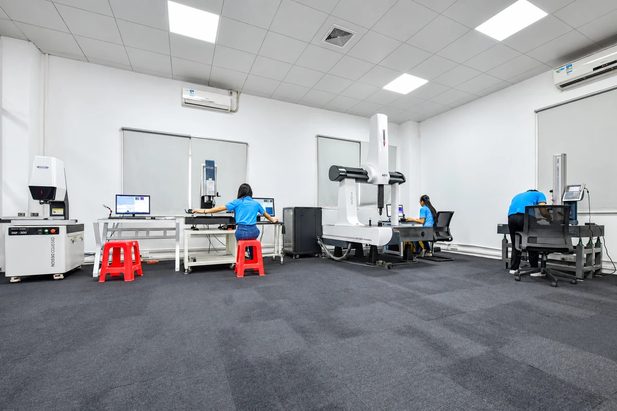
A sensible inspection plan may include first-article dimensional inspection, calibrated hand gauges for simple features, CMM or optical measurement for complex geometry, thread gauges, surface-roughness measurement and visual inspection under defined lighting or magnification. Use low and repeatable contact force on flexible features. Let parts reach the inspection environment before final measurement.
For reporting options, metrology and traceability, review our quality assurance and inspection systems
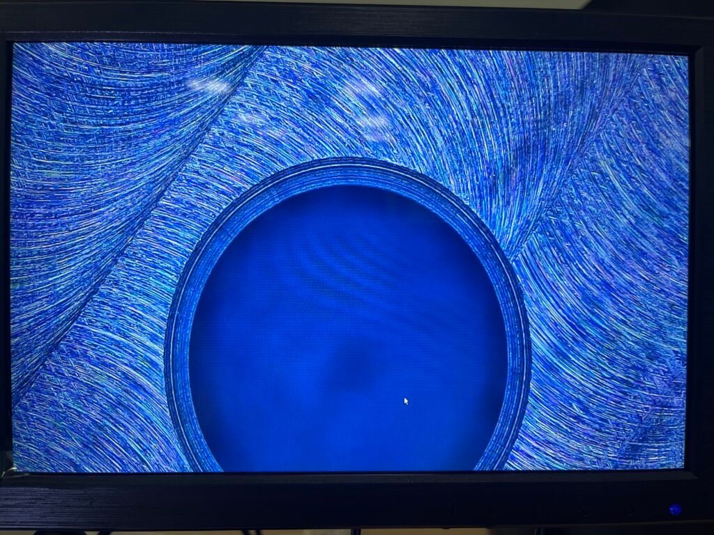
Common PEEK Machining Problems and Corrective Actions
|
Symptom |
Likely contributors |
Corrective direction |
|
Part moves after unclamping |
Excessive clamping, asymmetric stock removal, residual stress or local heating |
Reduce clamp load, balance roughing, allow stabilization and review intermediate annealing |
|
Smeared or glossy cut |
Rubbing tool, low effective chip load, poor evacuation or excessive heat |
Restore sharp cutting action, clear chips and review engagement and coolant strategy |
|
Heavy burrs |
Dull edge, unsupported exit, unsuitable tool geometry or heat |
Use a sharp edge, support the exit, adjust path direction and deburr with a controlled method |
|
Size drifts through the run |
Tool wear, part temperature, fixture movement or reinforced-grade abrasion |
Monitor tool life, stabilize temperature, verify fixture repeatability and inspect at intervals |
|
Fiber exposure or pullout |
Reinforced grade, worn tool or unsuitable finishing pass |
Confirm surface criteria, use wear-resistant tooling and validate a finishing strategy |
|
Distortion after annealing |
Unsupported geometry, unsuitable cycle or insufficient allowance |
Follow supplier cycle, support the part, leave finish stock and re-establish datums |
What Drives PEEK Machining Cost?
Material cost matters, but scrap risk and manufacturing time often matter more than the price per kilogram. Important cost drivers include:
- Exact grade, certified stock and minimum purchasable stock size
- Buy-to-fly ratio and the volume of material removed
- Number of setups and datum transfers
- Deep pockets, small cutters and long tool reach
- Reinforcement and tool-wear rate
- Tight tolerances applied to noncritical geometry
- Annealing, stabilization and repeated inspection stages
- Cleanliness, traceability, documentation and packaging
- Quantity, repeatability requirements and expected tool life
To reduce cost, start with near-size stock, open inaccessible pockets, standardize radii and hole sizes, distinguish critical from general tolerances and group features around stable datums. For repeat production, ask whether a fixture, dedicated tool or alternative stock form will reduce cycle time enough to justify the setup investment.
Do not request a price from a screenshot alone. Upload the CAD model and controlled drawing through our instant quote page so the quotation can reflect grade, geometry, inspection and documentation.
Prototype Versus Production Planning
A prototype should validate more than visual shape. Use the intended grade or a technically justified equivalent, then evaluate fit, load, thermal exposure, chemical environment, sterilization or cleaning, and dimensional stability. If the production method may change to injection molding, remember that a machined stock-shape prototype may not reproduce molded crystallinity, fiber orientation or weld-line behavior.
For production, control revision, stock supplier, lot traceability, validated tooling, fixture condition, in-process inspection frequency and nonconformance handling. Establish whether the first article represents one machine and lot or the full planned process. If volume increases, compare continued machining with molding or another near-net process rather than assuming the prototype route remains economical.
Our CNC production machining guide explains the broader transition from approved prototype to repeatable batch production. For another polymer-machining example, see CNC machining polypropylene: challenges and fixes.
RFQ Checklist for CNC-Machined PEEK Parts
- 3D CAD file in STEP format and a revision-controlled 2D drawing
- Exact PEEK manufacturer and grade, or the functional requirements for grade selection
- Stock-form and material-certificate requirements
- Quantity for prototype, first article and expected production batches
- Critical dimensions, datums, GD&T and general tolerance standard
- Surface roughness, burr, edge-break and cosmetic criteria
- Operating temperature, chemicals, pressure, load and mating materials
- Annealing or dimensional-stability requirement, if defined by the application
- Cleaning, contamination, traceability and packaging requirements
- Inspection report, CMM, FAI, certificate of conformance or other documentation
- Regulatory or industry standard that applies to the part
Final Engineering Takeaway
Successful PEEK CNC machining begins with the material specification and ends with an inspection plan. The most expensive failures usually come from treating all PEEK grades as identical, copying metal-design habits, forcing universal tolerances or using an annealing cycle without supplier guidance.
Identify the exact grade, protect the workpiece from heat and clamp distortion, balance material removal, validate tooling for reinforcement, and place tight controls only on functional features. That approach produces a more defensible quotation and a more stable part.
Ready for DFM feedback? Upload the CAD file, drawing, quantity and PEEK grade. Samshion will review stock selection, tool access, tolerance risk, inspection and documentation before production.
Frequently Asked Questions
Is PEEK difficult to machine?
Unfilled PEEK is generally machinable with sharp conventional tools and controlled heat. Reinforced grades can be significantly more abrasive. Difficulty increases with thin walls, deep pockets, heavy stock removal, tight free-state tolerances and strict contamination requirements.
Does every PEEK part need annealing?
No. Annealing is application- and process-dependent. It may help manage internal stress, crystallinity or high-temperature dimensional stability, but many parts do not require a secondary anneal. Follow the exact material and stock supplier’s guidance.
Can standard carbide tools machine PEEK?
Sharp carbide is a common starting point for unfilled PEEK and limited quantities. Filled grades or longer runs may justify coated carbide, PCD or another wear-resistant tool. Confirm tool life and surface quality through trials.
What tolerance can be held on PEEK?
It depends on grade, size, wall thickness, feature support, stock condition, temperature and inspection method. Put critical tolerances on a drawing and let the manufacturer review them against the actual geometry. Avoid applying one tight tolerance to every dimension.
Can industrial PEEK be used for an implant?
Do not assume so. Implantable applications require a specified medical or implant grade, traceability, applicable standards, biological evaluation and device-specific regulatory evidence. Ordinary industrial stock is not automatically implant approved.
How can I lower the cost of a machined PEEK part?
Use near-size stock, reduce deep material removal, open tool access, use standard cutters, relax noncritical tolerances, minimize setups and specify only the documentation the application needs. Include production quantity so fixture and tooling options can be evaluated.