The main 5-axis CNC machining limitations are tool and holder access, small internal corners, obstructed clamping faces, and the space available as the workpiece rotates. Additional axes give a machinist more approach angles, but a feature still needs a clear cutting path, stable support and a practical way to verify its dimensions.
For an engineer ordering a complex part, the useful question is whether the supplier can machine its difficult features repeatedly to the drawing. A shape that looks reachable in a CAD view may need another tool assembly, a different fixture, an additional setup or a second manufacturing process.
At SAMSHION, we usually address these restrictions through process adjustments first. This guide explains what we evaluate before recommending a design change, and what information helps a customer make that decision.
What five axes change and what they do not
A five-axis machine combines linear movement with two rotary axes to change the relationship between the tool and the workpiece. This can expose angled faces and help the cutter approach features that would be difficult from a fixed direction. It does not remove the physical dimensions of the spindle, holder, fixture or surrounding material.
Five-axis machining also does not mean that all five axes move during every cut. Indexed machining and simultaneous machining use the available axes differently. Our comparison of 3+2 and simultaneous five-axis machining explains that choice. Here, the focus is the restrictions that must be checked whichever strategy is selected.
The main limitations and the first checks
These checks interact. Raising a part may improve holder clearance while reducing available rotary space. Extending a cutter may reach the cavity floor while making the cut less stable. A successful adjustment must solve the original restriction without creating an unacceptable new one.
Tool holder interference is different from cutter access
The cutting edge can fit beside a wall even when the larger holder cannot pass it. Checking only the tool tip leaves out the shank, holder and spindle nose. Clearance also matters during entry, retraction and changes of orientation, not only at the final cutting position.
Our first options are to adjust the machining angle, change the cutter or holder, or alter the clamping arrangement. A different approach may keep the holder away from a tall wall without changing the customer’s part. A slimmer holder can help in some situations, but its fit and suitability must be assessed as part of the complete assembly.
Simply increasing tool projection is not an unlimited solution. It changes the assembly’s stiffness and may increase deflection or vibration. The drawing might demand a wall position or finish that the longer assembly cannot produce consistently.
The review should therefore identify exactly what is obstructed: the cutting edge, the noncutting portion of the tool, the holder, or the machine structure. Each points to a different remedy. A photograph can illustrate these relationships, but it cannot establish a safe numerical clearance.
Deep cavities and narrow slots still restrict machining
In deep cavity machining, reaching the bottom is only part of the problem. The tool must also have usable cutting geometry at the required depth, clearance from the cavity walls, and sufficient stability for the specified finish and size. Chip removal becomes another consideration in confined features.
Tilting can provide a shorter or clearer approach when the opening allows it. However, a narrow entrance may block a tilted tool assembly before it reaches the required surface. More rotary motion cannot create an opening where the part has none.
We first assess whether another angle, tool assembly or setup can reach the feature reliably. If those options remain unsuitable, we discuss a wider slot, a shallower pocket or removal of a nonessential recess. The customer must confirm that any change preserves weight, strength, assembly and other functional requirements.
There is no single depth limit that applies to every five-axis part. Depth must be considered together with feature width, tool diameter, material, access direction and tolerance. A supplier should explain the limiting combination rather than promise that all pockets below one depth are easy to machine.
Small internal corners can dictate the process
A rotating milling cutter leaves a radius in a typical internal pocket corner. Changing the tool angle does not make that radius disappear. When a drawing calls for a smaller corner, we first evaluate a smaller-diameter cutter and whether it can operate at the required reach.
A shallow corner and a deep corner with the same specified radius can require very different machining conditions. The smaller tool may fit both geometrically but be unsuitable at the greater reach. Our guide to internal radii in milling covers the design relationship in more detail.
Where the corner has a genuine assembly function, the required clearance must be retained. Where it has no such function, increasing the radius may allow a more practical tool. We do not assume that every small corner is unnecessary, and we do not replace it without approval. If milling remains unsuitable, EDM may be considered subject to the material and feature geometry.
Workholding can block the surface that needs machining
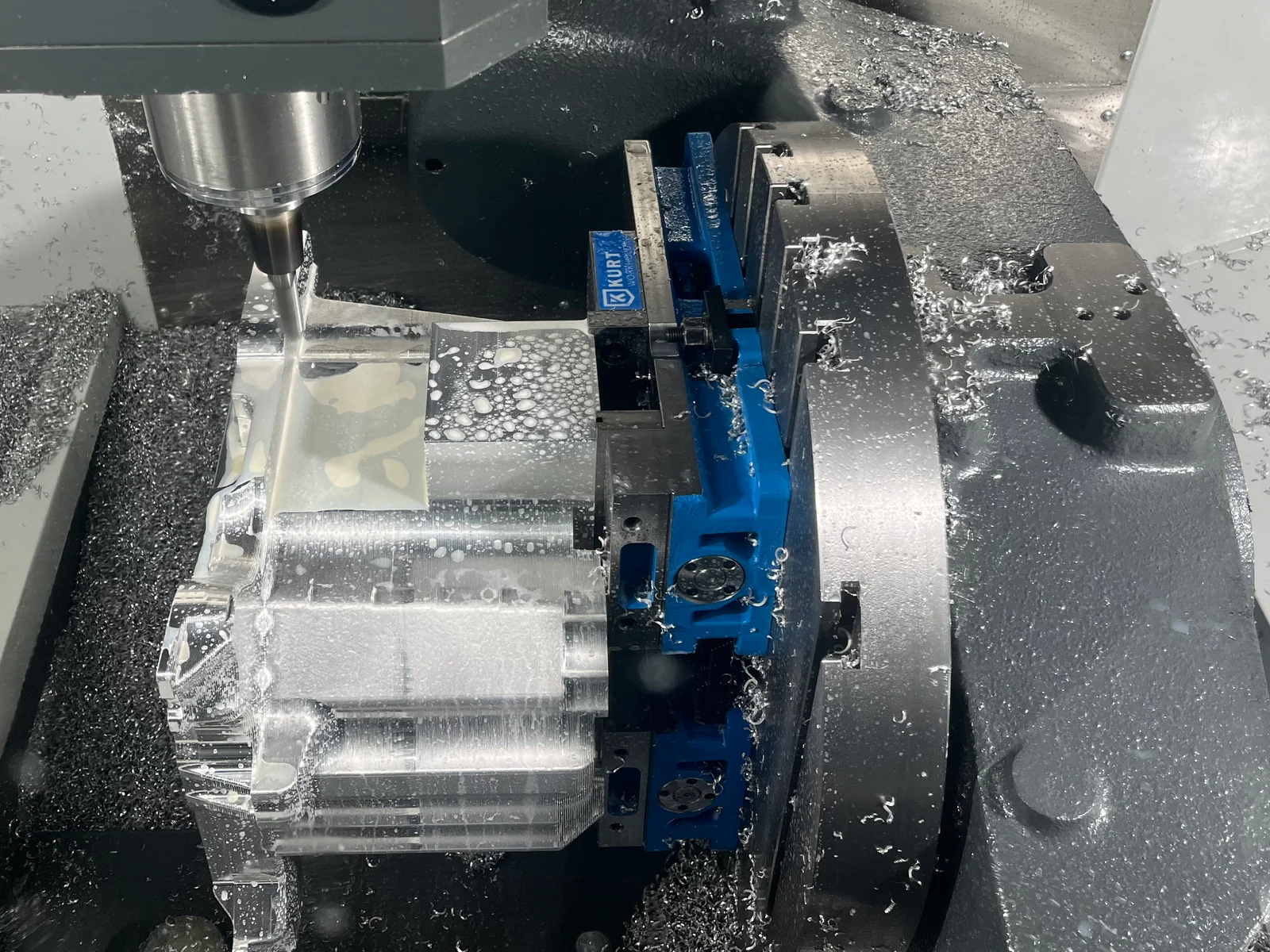
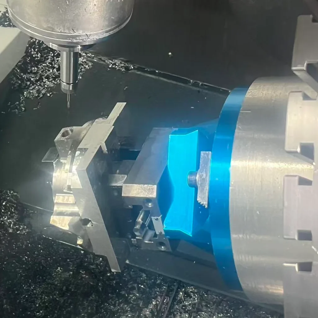
The part must remain securely held while material is removed. Vise jaws, clamps and supporting surfaces may occupy space that a later cutting operation needs. Five-axis workholding must balance access with support; exposing more of the part is useful only if the remaining grip is stable enough.
Changing the fixture or the part’s orientation can expose a blocked area. Raising the fixture may provide more space around the tool, but it also changes the assembly’s height and behavior during rotation. Reducing support simply to achieve a clear toolpath can leave a wall or projecting feature more vulnerable to movement under cutting loads.
Some parts require a separate setup to finish the original clamping face. Five axes do not guarantee one-setup completion, and the number of accessible faces is not a fixed rule derived from the number of machine axes.
Reclamping introduces a locating task. In our work, precision holes and planes can serve as locating references where suitable. These process references need to support the datum relationships specified on the drawing. Critical hole positions, mating faces and angular relationships should be considered when planning the second setup, not only when inspecting the finished part.
A part that fits the table may not fit during rotation
Nominal linear travel and table size are not a complete statement of usable part capacity. The fixture, protruding stock and the workpiece’s offset from the rotary center all affect the space occupied as the assembly moves. Tool length and the required approach angles affect the remaining clearance.
A setup may fit in one position but approach the spindle housing or another machine structure when tilted. The review needs to cover the intended movements and intermediate positions, rather than just the starting and finishing views.
When available space is insufficient, we consider repositioning the part, adjusting fixture height, selecting a machine with more usable space, or splitting the work into additional setups. A larger machine can address some space restrictions, but it will not necessarily resolve a narrow cavity entrance or a corner that requires unsuitable tooling.
For this reason, quote review should consider the combined part and workholding arrangement. Machine dimensions alone should not be treated as a guarantee that a specific component can be completed in one setup.
When EDM or a design change becomes appropriate
Our normal sequence is to evaluate machining angles, tools and workholding before asking the customer to alter the design. Many restrictions can be resolved within the manufacturing route. If not, the discussion should identify the affected feature and the drawing requirement it must satisfy.
Electrical discharge machining can be useful for some slots, cavities and difficult internal details in electrically conductive materials. Wire EDM needs a suitable wire path through the workpiece; sinker EDM uses a shaped electrode and requires practical electrode access. Neither process is a universal solution for inaccessible geometry, and both have their own dimensional and surface requirements. Makino’s explanation of the EDM process provides further background.
Another option is a customer-approved design revision. We may suggest increasing an internal radius, widening a narrow relief, reducing unnecessary pocket depth or simplifying a nonfunctional curved surface. Removing a weight-reduction feature can alter mass and structural behavior, so the manufacturing benefit alone is not enough to authorize the change.
If the available route cannot reliably meet the requirements, we need to say so. Reaching a feature once is not sufficient evidence that the planned process will produce an acceptable batch.
Checks continue from quotation to trial machining
Restrictions can become apparent at different stages. Initial drawing and 3D model review can reveal a difficult corner or obstructed opening. CAM programming can expose an interference at a specific tool orientation. Setup and trial machining can reveal practical issues that were not resolved by the earlier review.
An effective digital check should represent the stock, tool assembly and workholding actually intended for the operation. Machine motion and travel limits also need consideration. Autodesk’s guidance on collision avoidance and tool axis limits shows how these constraints affect toolpath calculation. Simulation depends on its inputs and does not replace controlled setup verification on the machine.
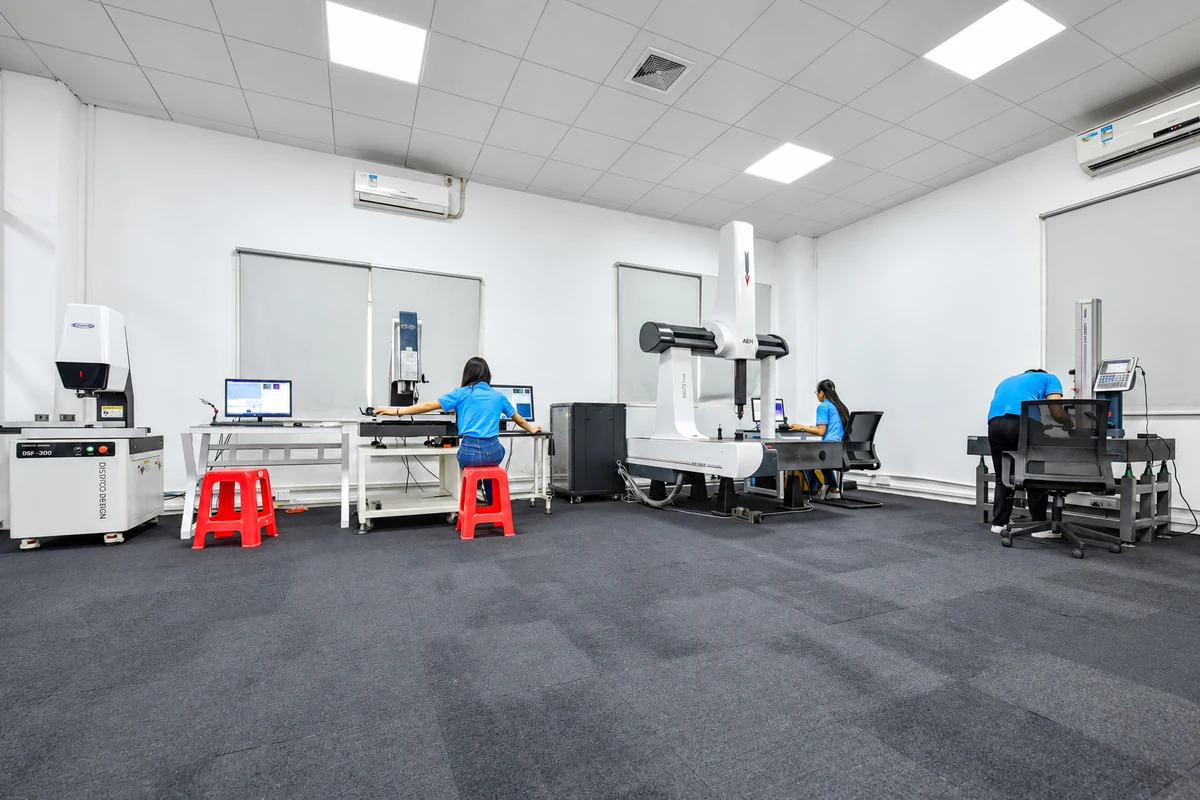
Dimensional verification is a separate task. A collision-free path does not prove that a thin wall remained in position or that features machined after reclamping satisfy their common datum requirements. Inspection must address the drawing characteristics and the condition in which the finished part will be accepted. Our CNC machining inspection guide explains how inspection methods relate to those requirements.
Information to include in a manufacturability review
Send the 3D model together with a dimensioned drawing. A model describes the shape, while the drawing and supporting notes explain which relationships and surfaces matter to function.
- Identify the material grade and condition, including any required heat treatment.
- Mark critical dimensions, geometric tolerances, datum features and mating surfaces.
- Explain the purpose of unusually small corners, deep pockets, narrow slots and undercuts.
- State the surface treatment and whether dimensions are accepted before or after that treatment.
- Provide the quantity and indicate where an alternative process or design revision may be discussed.
- Specify required inspection records and any restrictions on clamping marks or cosmetic surfaces.
A useful response should identify the restricted feature, explain the proposed machining route and flag decisions that need customer approval. This makes the tradeoff visible before an extra setup, EDM operation or geometry change becomes part of the order.
Common questions about five axis machining limits
Can five axis machining finish every face in one setup
No. Workholding may cover a surface that still needs machining, or another orientation may be necessary for tool access. An additional setup can be appropriate when its locating method preserves the required feature relationships.
Will a longer tool solve a deep pocket problem
Not necessarily. A longer tool may reach farther but provide less stiffness. Holder clearance, usable cutting length, chip removal and the required tolerance still need evaluation.
Does five axis machining eliminate internal corner radii
No. Typical milled internal pocket corners retain a radius related to the cutting tool. A smaller cutter, an approved radius change or a suitable secondary process may be needed.
Is simultaneous motion always needed for a difficult part
No. Some difficult features become accessible at a fixed indexed angle. Others benefit from changing tool orientation during cutting. The geometry and machining route determine the strategy; the machine’s axis count alone does not.
Discuss the difficult features before ordering
SAMSHION’s five-axis CNC machining service supports review of complex custom parts. If your design includes a deep recess, a small internal corner or closely related features on several faces, highlight those areas when you send a drawing and request a quote. We can evaluate process adjustments and discuss any design decisions needed before production.